EP1065760A1 - Connecteur à fiche pour des câbles ayant un pont de court-circuit - Google Patents
Connecteur à fiche pour des câbles ayant un pont de court-circuit Download PDFInfo
- Publication number
- EP1065760A1 EP1065760A1 EP00111607A EP00111607A EP1065760A1 EP 1065760 A1 EP1065760 A1 EP 1065760A1 EP 00111607 A EP00111607 A EP 00111607A EP 00111607 A EP00111607 A EP 00111607A EP 1065760 A1 EP1065760 A1 EP 1065760A1
- Authority
- EP
- European Patent Office
- Prior art keywords
- cable connector
- bridge element
- connector according
- contact elements
- short
- Prior art date
- Legal status (The legal status is an assumption and is not a legal conclusion. Google has not performed a legal analysis and makes no representation as to the accuracy of the status listed.)
- Ceased
Links
- 238000006073 displacement reaction Methods 0.000 claims description 10
- 238000009413 insulation Methods 0.000 claims description 10
- 210000002105 tongue Anatomy 0.000 claims description 6
- 239000004020 conductor Substances 0.000 claims description 4
- 239000002184 metal Substances 0.000 abstract 1
- 238000007373 indentation Methods 0.000 description 2
- 238000004519 manufacturing process Methods 0.000 description 2
- 238000012360 testing method Methods 0.000 description 2
- 230000006735 deficit Effects 0.000 description 1
- 238000011161 development Methods 0.000 description 1
- 230000018109 developmental process Effects 0.000 description 1
Images


Classifications
-
- H—ELECTRICITY
- H01—ELECTRIC ELEMENTS
- H01R—ELECTRICALLY-CONDUCTIVE CONNECTIONS; STRUCTURAL ASSOCIATIONS OF A PLURALITY OF MUTUALLY-INSULATED ELECTRICAL CONNECTING ELEMENTS; COUPLING DEVICES; CURRENT COLLECTORS
- H01R31/00—Coupling parts supported only by co-operation with counterpart
- H01R31/08—Short-circuiting members for bridging contacts in a counterpart
-
- H—ELECTRICITY
- H01—ELECTRIC ELEMENTS
- H01R—ELECTRICALLY-CONDUCTIVE CONNECTIONS; STRUCTURAL ASSOCIATIONS OF A PLURALITY OF MUTUALLY-INSULATED ELECTRICAL CONNECTING ELEMENTS; COUPLING DEVICES; CURRENT COLLECTORS
- H01R13/00—Details of coupling devices of the kinds covered by groups H01R12/70 or H01R24/00 - H01R33/00
- H01R13/02—Contact members
- H01R13/10—Sockets for co-operation with pins or blades
- H01R13/11—Resilient sockets
- H01R13/113—Resilient sockets co-operating with pins or blades having a rectangular transverse section
-
- H—ELECTRICITY
- H01—ELECTRIC ELEMENTS
- H01R—ELECTRICALLY-CONDUCTIVE CONNECTIONS; STRUCTURAL ASSOCIATIONS OF A PLURALITY OF MUTUALLY-INSULATED ELECTRICAL CONNECTING ELEMENTS; COUPLING DEVICES; CURRENT COLLECTORS
- H01R13/00—Details of coupling devices of the kinds covered by groups H01R12/70 or H01R24/00 - H01R33/00
- H01R13/46—Bases; Cases
- H01R13/50—Bases; Cases formed as an integral body
- H01R13/501—Bases; Cases formed as an integral body comprising an integral hinge or a frangible part
-
- H—ELECTRICITY
- H01—ELECTRIC ELEMENTS
- H01R—ELECTRICALLY-CONDUCTIVE CONNECTIONS; STRUCTURAL ASSOCIATIONS OF A PLURALITY OF MUTUALLY-INSULATED ELECTRICAL CONNECTING ELEMENTS; COUPLING DEVICES; CURRENT COLLECTORS
- H01R4/00—Electrically-conductive connections between two or more conductive members in direct contact, i.e. touching one another; Means for effecting or maintaining such contact; Electrically-conductive connections having two or more spaced connecting locations for conductors and using contact members penetrating insulation
- H01R4/24—Connections using contact members penetrating or cutting insulation or cable strands
- H01R4/2416—Connections using contact members penetrating or cutting insulation or cable strands the contact members having insulation-cutting edges, e.g. of tuning fork type
- H01R4/242—Connections using contact members penetrating or cutting insulation or cable strands the contact members having insulation-cutting edges, e.g. of tuning fork type the contact members being plates having a single slot
Definitions
- the invention relates to an electrical cable connector with in chambers a plastic housing arranged in a row contact elements, which - in Seen in the longitudinal direction - a first on each side Connection section, in particular insulation displacement contacts for stripping-free Connect one cable and a second on the opposite side Connection section, in particular a pair of spring tongues for connecting a Have plug contact pin, with a short-circuit bridging between two contact elements is provided.
- Such an electrical cable connector is from DE-OS 38 04 950 known. Electrical contact elements are in a row in one Plastic housing arranged and designed as leaf spring contacts, the corresponding conductor tracks in insulation displacement technology with the respective Contact springs are contacted. Such a connector can, for example to be plugged onto the edge of a printed circuit board in order to make the electrical Connection by means of the conductor tracks to those arranged on the circuit board to be able to manufacture electronic components. But it is also possible that Plug the connector onto a special pin header. In different Use cases, it is desirable with such a connector two or more electrical contact elements with short-circuit bridging to provide. It may be necessary to either immediately adjacent to bridge electrical contact elements, or any electrical Bridge contact elements within the row so that individual electrical Contact elements are skipped.
- the object of the invention is to create a short-circuit bridging that is easy to handle, while avoiding the disadvantages mentioned, with which the contacting possibilities of the connector are not restricted.
- the object is inventively achieved in that is formed in the connecting region of the contact element between the two connection portions, in particular the insulation displacement contacts and the spring tongue pair, is accessible from the side of the recess, that the recesses at least two of these contact elements by pushing an electrically conductive bridge member in transverse direction to each other Creation of the short-circuit bridging are connected and that the bridge element is press-fitted in the recesses.
- This ensures that due to the laterally arranged bridge element, no areas of the contact elements are closed by the bridge element, which are provided for the cable contact from the start, so that an impairment of the contacting possibilities of the connector is avoided by the teaching of the invention.
- the handling of the bridge element is very easy by pressing in the transverse direction and absolutely reliable by the press fit.
- the shape and manufacture of the short-circuit bridging can be designed extremely economically and technically effectively. The disadvantages of the prior art mentioned at the outset have been completely eliminated.
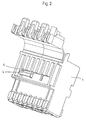
- Fig. 1 of the drawing shows all parts of an exploded view electrical cable connector, namely an empty plastic housing 1 with a plurality of chambers 2 arranged in series for a corresponding number of contact elements 3 and a short-circuit bridging 4.
- Fig. 2 of the drawing shows the cable connector of Fig. 1 in fully assembled Condition with opened housing cover. It is in each chamber 2 of Plastic housing 1 is a contact element 3 and is the Short-circuit bridging 4 through recesses 5 of the plastic housing 1 in the two chambers on the left in the drawing with the inserted ones Inserted contact elements such that these two contact elements are electrically interconnected by the isolating, intervening chamber wall of the plastic housing is bridged. More details on the structure of the contact elements 3 and Short-circuit bridging 4 result from the following description of the 3 to 5 of the drawing.
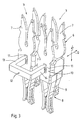
- Fig. 3 of the drawing two contact elements 3 are in an arrangement shown side by side in a row in perspective. It's the same arrangement in which they inserted into the associated chambers 2 of the plastic housing 1 and are then insulated from each other by the chamber walls.
- Each contact element 3 has - seen in the longitudinal direction L - on its in the Drawing top side a first connection section 6, namely Insulation displacement contacts 7 for stripping-free connection of a not shown Cable and on the opposite side a second connection section 8, namely a pair of spring tongues 9, for connecting a plug contact pin or a conductor track.
- the two connection sections 6 and 8 are approximately in the middle connected to each other by a connection area 10, in which a in Recess 11 extending approximately rectangular shape in the middle is trained.
- a U-shaped bridge element 12 In the two recesses 11 of the two contact elements 3 is a U-shaped bridge element 12 from the side in the transverse direction Q indentable, which is an electrically conductive connection of the two Manufactures contact elements 3 with each other and thus a short-circuit bridging represents.
- the existing relation to the housing 1 is the Fig. 3 Drawing not removable, but can be seen from Fig. 2 of the drawing. Accordingly, the bridge element 12 passes through the plastic housing 1 of outside through the two lateral recesses 5 and extend the free Legs 13, 14 as contact arms in the interior of the adjacent chambers 2 and then engage in the recesses 11 of the two contact elements 3 of FIG. 3 to establish a conductive connection.
- the bridge element 12 must be pressed into the recesses 11, as by appropriate Dimensions of the free legs 13 and 14 on the one hand and the recesses 11 on the other hand, an interference fit is provided as a forced fit.
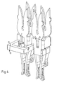
- Fig. 4 of the drawing illustrates the possibilities for producing the Press fit over correspondingly set dimensions A-A of the recesses and B-B of the free legs 13 or 14 of the bridge element or by corresponding setting of the dimensions C-C of the recesses 11 and the dimension D-D of the bridge element 12.
- the dimension D-D is also designed so that a contact and Short-circuit testing using a test pin is possible.
- Fig. 5 of the drawing shows the assembled short-circuit bypass 4 on the two Contact elements 3 omitting the plastic housing 1.
Landscapes
- Coupling Device And Connection With Printed Circuit (AREA)
- Connector Housings Or Holding Contact Members (AREA)
- Connections By Means Of Piercing Elements, Nuts, Or Screws (AREA)
- Multi-Conductor Connections (AREA)
Applications Claiming Priority (2)
| Application Number | Priority Date | Filing Date | Title |
|---|---|---|---|
| DE29910867U DE29910867U1 (de) | 1999-06-28 | 1999-06-28 | Elektrischer Kabelsteckverbinder mit Kurzschlußüberbrückung |
| DE29910867U | 1999-06-28 |
Publications (1)
| Publication Number | Publication Date |
|---|---|
| EP1065760A1 true EP1065760A1 (fr) | 2001-01-03 |
Family
ID=8075128
Family Applications (1)
| Application Number | Title | Priority Date | Filing Date |
|---|---|---|---|
| EP00111607A Ceased EP1065760A1 (fr) | 1999-06-28 | 2000-05-31 | Connecteur à fiche pour des câbles ayant un pont de court-circuit |
Country Status (4)
| Country | Link |
|---|---|
| US (1) | US6368128B1 (fr) |
| EP (1) | EP1065760A1 (fr) |
| JP (1) | JP2001023743A (fr) |
| DE (1) | DE29910867U1 (fr) |
Cited By (4)
| Publication number | Priority date | Publication date | Assignee | Title |
|---|---|---|---|---|
| DE102010040542A1 (de) * | 2010-09-10 | 2012-03-15 | Würth Elektronik eiSos Gmbh & Co. KG | Überbrückungsbaustein |
| WO2022247985A1 (fr) * | 2021-05-26 | 2022-12-01 | Harting Electric Stiftung & Co. Kg | Connecteur mâle à fonction de pontage |
| WO2026021937A1 (fr) * | 2024-07-25 | 2026-01-29 | Rosenberger Hochfrequenztechnik Gmbh & Co. Kg | Fiche de connexion en plusieurs parties et topologie de réseau électrique |
| EP4712277A1 (fr) * | 2024-09-12 | 2026-03-18 | Rosenberger Hochfrequenztechnik GmbH & Co. KG | Connecteur électrique, élément de connexion électrique d'une topologie de réseau et topologie de réseau électrique |
Families Citing this family (26)
| Publication number | Priority date | Publication date | Assignee | Title |
|---|---|---|---|---|
| DE19953593A1 (de) * | 1999-03-12 | 2000-09-28 | Grote & Hartmann | Elektrischer Steckverbinder mit mindestens einem Schneidklemmkontaktelement aus einem Blechstanzteil sowie korrespondierender Gegensteckverbinder hierzu |
| WO2000055943A1 (fr) | 1999-03-12 | 2000-09-21 | Grote & Hartmann Gmbh & Co. Kg | Connecteur electrique enfichable comprenant au moins un element de contact a guillotine constitue par une partie estampee en tole, et contre-connecteur correspondant |
| FR2803442B1 (fr) * | 2000-01-04 | 2005-10-07 | Entrelec Sa | Piece de connexion auto-denudante pouvant etre reliee a une piece de connexion voisine |
| GB2358093B (en) | 2000-01-19 | 2003-10-08 | Entrelec Sa | Insulation-displacement connecting piece able to be connected to an adjacent connecting piece |
| DE10063482B4 (de) * | 2000-12-06 | 2007-03-15 | Phoenix Contact Gmbh & Co. Kg | Elektrische Klemme und Baueinheit aus einem elektronischen Gerät und einer in einem ortsfesten Gehäuse angeordneten elektrischen Klemme |
| US6688920B2 (en) * | 2001-01-23 | 2004-02-10 | Tyco Electronics Amp Gmbh | Connector assembly |
| JP2004273154A (ja) * | 2003-03-05 | 2004-09-30 | Yazaki Corp | ジョイントコネクタ及び端子 |
| JP4263533B2 (ja) * | 2003-05-15 | 2009-05-13 | 矢崎総業株式会社 | ジョイントコネクタブロック |
| DE202004011099U1 (de) * | 2004-07-13 | 2005-02-24 | Stocko Contact Gmbh & Co. Kg | Elektrisches Steckergehäuse und Steckverbinder |
| DE102005041778A1 (de) * | 2005-09-01 | 2007-03-08 | Phoenix Contact Gmbh & Co. Kg | Elektrische Anschlußanordnung |
| JP4164520B2 (ja) * | 2006-07-26 | 2008-10-15 | 日本圧着端子製造株式会社 | プリント配線板間接続コネクタ |
| EP2070163A1 (fr) * | 2006-09-14 | 2009-06-17 | 3M Innovative Properties Company | Système de connecteur électrique |
| CN201029151Y (zh) * | 2006-12-26 | 2008-02-27 | 富士康(昆山)电脑接插件有限公司 | 电连接器 |
| DE202008000939U1 (de) * | 2008-01-22 | 2008-03-20 | CCS Technology, Inc., Wilmington | Aderanlegekappe eines elektrischen Steckverbinders |
| DE102008020511A1 (de) * | 2008-04-23 | 2009-11-05 | Mc Technology Gmbh | Kontaktelement für eine Anschlussklemme, Anschlussklemme und Steckbrücke für ein Kontaktelement |
| JP5390792B2 (ja) * | 2008-05-23 | 2014-01-15 | 古河電気工業株式会社 | 接続部材 |
| EP2209166B1 (fr) * | 2009-01-14 | 2017-09-27 | Delphi Technologies, Inc. | Connexion électrique |
| DE102010022970A1 (de) * | 2010-06-08 | 2011-12-08 | Green Inno Gmbh | Kabelverbindungseinrichtung |
| WO2013054910A1 (fr) | 2011-10-14 | 2013-04-18 | オムロン株式会社 | Borne |
| GB201204866D0 (en) * | 2012-03-20 | 2012-05-02 | Trw Ltd | Fork type electrical connector |
| CN104466517A (zh) * | 2014-12-10 | 2015-03-25 | 贵州航天电器股份有限公司 | 一种短路保护连接器 |
| KR101734656B1 (ko) * | 2015-06-26 | 2017-05-11 | 현대자동차주식회사 | 조인트 커넥터 |
| KR102251883B1 (ko) * | 2015-12-29 | 2021-05-14 | 현대자동차주식회사 | 와이어 분기 연결용 커넥터 |
| MX379877B (es) * | 2017-08-02 | 2025-03-11 | Kyocera Avx Components Corp | Conector de cable a cable con derivacion |
| WO2019097368A1 (fr) | 2017-11-15 | 2019-05-23 | Avx Corporation | Connecteur fil-à-fil avec contact de connexion autodénudant pour un soulagement de contrainte intégré |
| DE102020102605B3 (de) * | 2020-02-03 | 2021-06-10 | WAGO Verwaltungsgesellschaft mit beschränkter Haftung | Kontakteinsatz |
Citations (3)
| Publication number | Priority date | Publication date | Assignee | Title |
|---|---|---|---|---|
| US4456317A (en) * | 1983-03-10 | 1984-06-26 | Amp Incorporated | Commoning strip |
| EP0387772A1 (fr) * | 1989-03-13 | 1990-09-19 | The Whitaker Corporation | Ensemble d'interconnexion électrique |
| EP0634819A2 (fr) * | 1993-07-16 | 1995-01-18 | Sumitomo Wiring Systems, Ltd. | Appareil et méthode pour la connexion mécanique et électrique des terminaux métalliques dans un boîtier |
Family Cites Families (6)
| Publication number | Priority date | Publication date | Assignee | Title |
|---|---|---|---|---|
| DE3804950A1 (de) | 1987-09-11 | 1989-03-30 | Stocko Metallwarenfab Henkels | Kurzschlussueberbrueckung |
| JPH0734475B2 (ja) | 1989-03-10 | 1995-04-12 | 株式会社東芝 | 半導体装置 |
| GB2233164A (en) * | 1989-05-24 | 1991-01-02 | Cinch Connectors Ltd | Selective shorting of plug pins/socket contacts in an electrical connector |
| JP2885029B2 (ja) * | 1993-11-22 | 1999-04-19 | 住友電装株式会社 | バスバーを収容した電気接続箱の製造方法および該方法で製造された電気接続箱 |
| CA2142131A1 (fr) * | 1995-02-09 | 1996-08-10 | Benoit Chevarie | Ensemble de connecteurs de telecommunication multiborne et bornes connexes |
| US5788519A (en) | 1995-05-02 | 1998-08-04 | Yazaki Corporation | Waterproof grounding connector and method of assembling same |
-
1999
- 1999-06-28 DE DE29910867U patent/DE29910867U1/de not_active Expired - Lifetime
-
2000
- 2000-05-31 EP EP00111607A patent/EP1065760A1/fr not_active Ceased
- 2000-06-20 JP JP2000183895A patent/JP2001023743A/ja active Pending
- 2000-06-28 US US09/606,322 patent/US6368128B1/en not_active Expired - Fee Related
Patent Citations (3)
| Publication number | Priority date | Publication date | Assignee | Title |
|---|---|---|---|---|
| US4456317A (en) * | 1983-03-10 | 1984-06-26 | Amp Incorporated | Commoning strip |
| EP0387772A1 (fr) * | 1989-03-13 | 1990-09-19 | The Whitaker Corporation | Ensemble d'interconnexion électrique |
| EP0634819A2 (fr) * | 1993-07-16 | 1995-01-18 | Sumitomo Wiring Systems, Ltd. | Appareil et méthode pour la connexion mécanique et électrique des terminaux métalliques dans un boîtier |
Cited By (5)
| Publication number | Priority date | Publication date | Assignee | Title |
|---|---|---|---|---|
| DE102010040542A1 (de) * | 2010-09-10 | 2012-03-15 | Würth Elektronik eiSos Gmbh & Co. KG | Überbrückungsbaustein |
| DE102010040542B4 (de) * | 2010-09-10 | 2016-05-25 | Würth Elektronik eiSos Gmbh & Co. KG | Überbrückungsbaustein und Verfahren mit einem Überbrückungsbaustein |
| WO2022247985A1 (fr) * | 2021-05-26 | 2022-12-01 | Harting Electric Stiftung & Co. Kg | Connecteur mâle à fonction de pontage |
| WO2026021937A1 (fr) * | 2024-07-25 | 2026-01-29 | Rosenberger Hochfrequenztechnik Gmbh & Co. Kg | Fiche de connexion en plusieurs parties et topologie de réseau électrique |
| EP4712277A1 (fr) * | 2024-09-12 | 2026-03-18 | Rosenberger Hochfrequenztechnik GmbH & Co. KG | Connecteur électrique, élément de connexion électrique d'une topologie de réseau et topologie de réseau électrique |
Also Published As
| Publication number | Publication date |
|---|---|
| US6368128B1 (en) | 2002-04-09 |
| DE29910867U1 (de) | 1999-09-30 |
| JP2001023743A (ja) | 2001-01-26 |
Similar Documents
| Publication | Publication Date | Title |
|---|---|---|
| EP1065760A1 (fr) | Connecteur à fiche pour des câbles ayant un pont de court-circuit | |
| EP0921592B1 (fr) | Connecteur pour conducteurs électriques | |
| DE102006052894B4 (de) | Reihenklemme, Prüfstecker und Prüfklemmenblock | |
| EP2756554B1 (fr) | Borne serre-fils électrique et bloc de bornes serre-fils électriques | |
| DE2941029C2 (fr) | ||
| DE4411306C1 (de) | Elektrische Anschluß- und/oder Verbindungsklemme, insbesondere Reihenklemme, mit Steckbrücke sowie eine Steckbrücke | |
| DE4433983A1 (de) | Anschlußklemme für elektrische Installationen | |
| DE19736739A1 (de) | Elektrische Anschlußklemme, insbesondere für den Einsatz auf Leiterplatten | |
| DE202011108572U1 (de) | Adapter und Set aus Reihenklemme und Adapter | |
| EP1113525B1 (fr) | Barette à bornes, en particulier pour transformateur de mesure avec dispositif de pontage transversal | |
| EP1848071A2 (fr) | Connecteur à fiches doté de contacts anti-court-circuit | |
| DE19603960A1 (de) | Mehrpoliger Abzweig-Steckverbinder | |
| DE10134417C1 (de) | Elektrische Anschluß- oder Verbindungseinrichtung | |
| DE19749622C1 (de) | Elektrische Klemme | |
| EP1859517B1 (fr) | Adaptateur de connexions ou d'appareils | |
| DE4038362C2 (fr) | ||
| EP0984513B1 (fr) | Pièce d'insertion pour un connecteur industriel | |
| EP0736929A1 (fr) | Elément de contact électrique et boîtier en plastique pour la réception cet élément | |
| EP1331693B1 (fr) | Plaque à bornes | |
| EP1020954B1 (fr) | Borne de connexion électrique | |
| BE1026787B1 (de) | Anschlussvorrichtung für elektrische Leiter | |
| DE19823647C1 (de) | Mehrpolige Anschlußklemme für elektrische Leiter | |
| DE102007052462A1 (de) | Leiterplattensteckverbinder | |
| EP1130684B1 (fr) | Shunt for a staged terminal block | |
| DE102005016534A1 (de) | Elektrische Reihenklemmen |
Legal Events
| Date | Code | Title | Description |
|---|---|---|---|
| PUAI | Public reference made under article 153(3) epc to a published international application that has entered the european phase |
Free format text: ORIGINAL CODE: 0009012 |
|
| AK | Designated contracting states |
Kind code of ref document: A1 Designated state(s): DE FR GB IT SE |
|
| AX | Request for extension of the european patent |
Free format text: AL;LT;LV;MK;RO;SI |
|
| 17P | Request for examination filed |
Effective date: 20001212 |
|
| AKX | Designation fees paid |
Free format text: DE FR GB IT SE |
|
| 17Q | First examination report despatched |
Effective date: 20041217 |
|
| STAA | Information on the status of an ep patent application or granted ep patent |
Free format text: STATUS: THE APPLICATION HAS BEEN REFUSED |
|
| 18R | Application refused |
Effective date: 20050402 |