EP1066964A1 - Antriebslagerung von rotierenden Werkzeugen in Druckmaschinen - Google Patents
Antriebslagerung von rotierenden Werkzeugen in Druckmaschinen Download PDFInfo
- Publication number
- EP1066964A1 EP1066964A1 EP99113288A EP99113288A EP1066964A1 EP 1066964 A1 EP1066964 A1 EP 1066964A1 EP 99113288 A EP99113288 A EP 99113288A EP 99113288 A EP99113288 A EP 99113288A EP 1066964 A1 EP1066964 A1 EP 1066964A1
- Authority
- EP
- European Patent Office
- Prior art keywords
- drive shaft
- drive
- cone
- printing machines
- tool
- Prior art date
- Legal status (The legal status is an assumption and is not a legal conclusion. Google has not performed a legal analysis and makes no representation as to the accuracy of the status listed.)
- Granted
Links
- 238000007639 printing Methods 0.000 title claims description 21
- 238000004080 punching Methods 0.000 description 2
- 238000004804 winding Methods 0.000 description 2
- 230000003750 conditioning effect Effects 0.000 description 1
- 238000010276 construction Methods 0.000 description 1
- 230000001419 dependent effect Effects 0.000 description 1
- 238000001035 drying Methods 0.000 description 1
- 238000004049 embossing Methods 0.000 description 1
- 238000007650 screen-printing Methods 0.000 description 1
Images
Classifications
-
- F—MECHANICAL ENGINEERING; LIGHTING; HEATING; WEAPONS; BLASTING
- F16—ENGINEERING ELEMENTS AND UNITS; GENERAL MEASURES FOR PRODUCING AND MAINTAINING EFFECTIVE FUNCTIONING OF MACHINES OR INSTALLATIONS; THERMAL INSULATION IN GENERAL
- F16D—COUPLINGS FOR TRANSMITTING ROTATION; CLUTCHES; BRAKES
- F16D1/00—Couplings for rigidly connecting two coaxial shafts or other movable machine elements
- F16D1/06—Couplings for rigidly connecting two coaxial shafts or other movable machine elements for attachment of a member on a shaft or on a shaft-end
- F16D1/08—Couplings for rigidly connecting two coaxial shafts or other movable machine elements for attachment of a member on a shaft or on a shaft-end with clamping hub; with hub and longitudinal key
- F16D1/09—Couplings for rigidly connecting two coaxial shafts or other movable machine elements for attachment of a member on a shaft or on a shaft-end with clamping hub; with hub and longitudinal key with radial clamping due to axial loading of at least one pair of conical surfaces
- F16D1/092—Couplings for rigidly connecting two coaxial shafts or other movable machine elements for attachment of a member on a shaft or on a shaft-end with clamping hub; with hub and longitudinal key with radial clamping due to axial loading of at least one pair of conical surfaces the pair of conical mating surfaces being provided on the coupled hub and shaft
-
- B—PERFORMING OPERATIONS; TRANSPORTING
- B41—PRINTING; LINING MACHINES; TYPEWRITERS; STAMPS
- B41F—PRINTING MACHINES OR PRESSES
- B41F13/00—Common details of rotary presses or machines
- B41F13/008—Mechanical features of drives, e.g. gears, clutches
Definitions
- the present invention relates to a drive mounting of rotating tools in printing machines, especially label printing machines, on the drive shaft, e.g. the drive shaft a servo motor.
- each printing unit can be replaced very quickly and easily can be. This allows a printing press to work optimally be used.
- the object of the present invention was to provide a drive mounting between a rotating tool and a drive shaft to create which in terms of a tool change can be solved very quickly and the precision of storage improved as far as possible compared to conventional solutions becomes.
- the construction of the drive bearing according to the invention becomes a geometrically optimal one for the rotating printing tools Connection between tool and drive created, which is quick and easy to solve, which is a quick change allowed by tools.
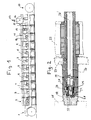
- Fig. 1 shows a modern printing machine, the Parts and printing units electronically controlled via each own servomotors are driven.
- the printing press points a web unwinding unit 1, a conditioning unit 2, e.g. a screen printing unit 3, a book printing unit 4, a plurality further printing units 5 - 9, a flexographic printing unit 10 with Drying device 11, a supply part 12, a processing part 13 with punching unit 14, winding unit 15 and cutting unit 16, and a winding unit 17 as a storage part.
- the corresponding units come for use.
- the rotating tools are quickly interchangeable in order for new ones Tasks available.
- Fig. 2 shows how a rotating tool 18 over it attached element 19 with axially projecting connecting cone 20 with the drive shaft 21 of a servo motor 22 (schematic shown) detachable, but absolutely firmly connected or coupled (the other end of the tool 18 is known per se Manner in a warehouse, e.g. a needle bearing, which in an easily detachable cheek, not shown Frame is arranged).
- the motor 22 is also on one Cheek 23 attached to a base frame of the unit.
- the servo motor 22 serves e.g. the drive of a forme cylinder, an impression cylinder or the drive of an inking unit.
- the frame cheeks After extending or swiveling the frame cheeks (not shown) are each equipped with a connecting cone Tools (forme cylinder, impression cylinder, inking unit), into the conical recesses 24 of the drive shafts 21 introduced and precisely centered in it. So the tool sits in the correct angular position on the drive shaft 21, a pin 25 is provided which connects the connecting cone 20 in holds the correct position (may also help to prevent rotation at).
- the actual connection is made by friction between the surfaces of the cone 20 and the conical Recess 24 by the connecting cone 20 by means of a Tension rod 26 (26 ') is tensioned against the drive shaft 21 (by tightening on the right-hand end, e.g. via a screw drive).
- the tie rod (see Fig. 2) engages in a central undercut Bore 27 of the cone 20, where there is an expansion head 28, which can be opened to the cone 20 to attract and to create an optimal drive connection. To loosen the drive connection or the drive mounting only the tie rod 26 (with expansion head 28) can be loosened.
- a Pressure medium e.g. compressed air
- channels 29 For simple, quick loosening of the cone connection, you can use a Pressure medium (e.g. compressed air) can be used through channels 29.
- a Pressure medium e.g. compressed air
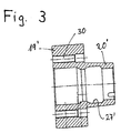
- FIG. 3 of the drawing shows a variant of an element 19 ' with connecting cone 20 'and undercut, central bore 27 '.
- This element 19 ' is suitable for screwing on axially a tool by means of several screws (screw holes 30).
Landscapes
- Engineering & Computer Science (AREA)
- General Engineering & Computer Science (AREA)
- Mechanical Engineering (AREA)
- Rotary Presses (AREA)
- Turbine Rotor Nozzle Sealing (AREA)
- Constituent Portions Of Griding Lathes, Driving, Sensing And Control (AREA)
- Auxiliary Devices For And Details Of Packaging Control (AREA)
- Supplying Of Containers To The Packaging Station (AREA)
- Automatic Tool Replacement In Machine Tools (AREA)
- Turning (AREA)
- Perforating, Stamping-Out Or Severing By Means Other Than Cutting (AREA)
Abstract
Description
- Fig. 1
- rein schematisch, eine Druckmaschine mit einer Vielzahl von Druckeinheiten und Zusatzteilen;
- Fig. 2
- eine erfindungsgemässe Antriebslagerung, und
- Fig. 3
- eine Variante eines Verbindungskonus.
Claims (3)
- Antriebslagerung von rotierenden Werkzeugen in Druckmaschinen, insbesondere Etikettendruckmaschinen, an der Antriebswelle, dadurch gekennzeichnet, dass an der Schnittstelle zwischen Werkzeug und Antriebswelle ein Element in der Werkzeugachse an diesem angeordnet ist, welches Element mit einem axial abstehenden Verbindungskonus versehen ist, welcher seinerseits in eine entsprechende Ausnehmung der Antriebswelle eingreift, und darin in einer vorbestimmten Winkelstellung lösbar gehalten und gegen Verdrehung gesichert zentriert ist.
- Antriebslagerung nach Anspruch 1, dadurch gekennzeichnet, dass zum lösbaren Halten des Verbindungskonus letzterer mit einer hinterschnittenen Innenbohrung versehen ist, in welche ein durch die Antriebswelle des Motors führender Spannstab mit Spreizkopf eingreift, um den Konus gegen die entsprechende Wand der Gegenausnehmung in der Antriebswelle anzulegen.
- Antriebslagerung nach Anspruch 2, dadurch gekennzeichnet, dass Mittel vorgesehen sind, um den vom Spannstab freigegebenen Konus mittels eines Druckmediums, z.B. Druckluft, vom Sitz in der Antriebswelle zu lösen.
Priority Applications (10)
| Application Number | Priority Date | Filing Date | Title |
|---|---|---|---|
| ES99113288T ES2191999T3 (es) | 1999-07-09 | 1999-07-09 | Soporte de accionamiento para herramientas rotativas en maquinas impresoras. |
| DK99113288T DK1066964T3 (da) | 1999-07-09 | 1999-07-09 | Drivlejring af roterende værktøjer i trykkemaskiner |
| EP99113288A EP1066964B1 (de) | 1999-07-09 | 1999-07-09 | Antriebslagerung von rotierenden Werkzeugen in Druckmaschinen |
| DE59904333T DE59904333D1 (de) | 1999-07-09 | 1999-07-09 | Antriebslagerung von rotierenden Werkzeugen in Druckmaschinen |
| AT99113288T ATE232796T1 (de) | 1999-07-09 | 1999-07-09 | Antriebslagerung von rotierenden werkzeugen in druckmaschinen |
| JP2001509375A JP2003504240A (ja) | 1999-07-09 | 2000-07-06 | 印刷機における回転工具の駆動軸受装置 |
| PCT/CH2000/000373 WO2001003929A1 (de) | 1999-07-09 | 2000-07-06 | Antriebslagerung von rotierenden werkzeugen in druckmaschinen |
| AU53861/00A AU5386100A (en) | 1999-07-09 | 2000-07-06 | Drive bearing arrangement of rotating tools in printing machines |
| CNB008101426A CN1153668C (zh) | 1999-07-09 | 2000-07-06 | 印刷机中的旋转工具的驱动支承 |
| HK01104762.7A HK1035697B (en) | 2001-07-10 | Drive bearing of rotating tools in printing machines |
Applications Claiming Priority (1)
| Application Number | Priority Date | Filing Date | Title |
|---|---|---|---|
| EP99113288A EP1066964B1 (de) | 1999-07-09 | 1999-07-09 | Antriebslagerung von rotierenden Werkzeugen in Druckmaschinen |
Publications (2)
| Publication Number | Publication Date |
|---|---|
| EP1066964A1 true EP1066964A1 (de) | 2001-01-10 |
| EP1066964B1 EP1066964B1 (de) | 2003-02-19 |
Family
ID=8238551
Family Applications (1)
| Application Number | Title | Priority Date | Filing Date |
|---|---|---|---|
| EP99113288A Expired - Lifetime EP1066964B1 (de) | 1999-07-09 | 1999-07-09 | Antriebslagerung von rotierenden Werkzeugen in Druckmaschinen |
Country Status (9)
| Country | Link |
|---|---|
| EP (1) | EP1066964B1 (de) |
| JP (1) | JP2003504240A (de) |
| CN (1) | CN1153668C (de) |
| AT (1) | ATE232796T1 (de) |
| AU (1) | AU5386100A (de) |
| DE (1) | DE59904333D1 (de) |
| DK (1) | DK1066964T3 (de) |
| ES (1) | ES2191999T3 (de) |
| WO (1) | WO2001003929A1 (de) |
Cited By (2)
| Publication number | Priority date | Publication date | Assignee | Title |
|---|---|---|---|---|
| DE10341850A1 (de) * | 2003-09-09 | 2005-04-07 | Windmöller & Hölscher Kg | Druckwerk mit schnell auswechselbarem Walzendorn einer Druck- oder Rasterwalze |
| DE102006006008A1 (de) * | 2006-02-08 | 2007-08-16 | Windmöller & Hölscher Kg | Formzylinderankopplung |
Families Citing this family (1)
| Publication number | Priority date | Publication date | Assignee | Title |
|---|---|---|---|---|
| DE102020106278A1 (de) * | 2020-03-09 | 2021-09-09 | Saurer Spinning Solutions Gmbh & Co. Kg | Vorrichtung zur Drehmomentübertragung |
Citations (4)
| Publication number | Priority date | Publication date | Assignee | Title |
|---|---|---|---|---|
| US2890517A (en) * | 1958-06-27 | 1959-06-16 | Magnat Machinery & Pattern Cor | Mechanism for securing roll to shaft |
| US3086799A (en) * | 1960-03-17 | 1963-04-23 | Harris Intertype Corp | Key-type mounting |
| EP0392323A1 (de) * | 1989-04-13 | 1990-10-17 | WindmÀ¶ller & Hölscher | Einen Achsversatz ausgleichende Wellen-Kupplung |
| EP0545013A1 (de) * | 1991-11-18 | 1993-06-09 | WindmÀ¶ller & Hölscher | Vorrichtung zum Kuppeln eines Wickelwellenzapfens mit einem Antriebswellenzapfen |
-
1999
- 1999-07-09 DK DK99113288T patent/DK1066964T3/da active
- 1999-07-09 EP EP99113288A patent/EP1066964B1/de not_active Expired - Lifetime
- 1999-07-09 AT AT99113288T patent/ATE232796T1/de not_active IP Right Cessation
- 1999-07-09 DE DE59904333T patent/DE59904333D1/de not_active Expired - Lifetime
- 1999-07-09 ES ES99113288T patent/ES2191999T3/es not_active Expired - Lifetime
-
2000
- 2000-07-06 WO PCT/CH2000/000373 patent/WO2001003929A1/de not_active Ceased
- 2000-07-06 CN CNB008101426A patent/CN1153668C/zh not_active Expired - Lifetime
- 2000-07-06 AU AU53861/00A patent/AU5386100A/en not_active Abandoned
- 2000-07-06 JP JP2001509375A patent/JP2003504240A/ja not_active Withdrawn
Patent Citations (4)
| Publication number | Priority date | Publication date | Assignee | Title |
|---|---|---|---|---|
| US2890517A (en) * | 1958-06-27 | 1959-06-16 | Magnat Machinery & Pattern Cor | Mechanism for securing roll to shaft |
| US3086799A (en) * | 1960-03-17 | 1963-04-23 | Harris Intertype Corp | Key-type mounting |
| EP0392323A1 (de) * | 1989-04-13 | 1990-10-17 | WindmÀ¶ller & Hölscher | Einen Achsversatz ausgleichende Wellen-Kupplung |
| EP0545013A1 (de) * | 1991-11-18 | 1993-06-09 | WindmÀ¶ller & Hölscher | Vorrichtung zum Kuppeln eines Wickelwellenzapfens mit einem Antriebswellenzapfen |
Cited By (3)
| Publication number | Priority date | Publication date | Assignee | Title |
|---|---|---|---|---|
| DE10341850A1 (de) * | 2003-09-09 | 2005-04-07 | Windmöller & Hölscher Kg | Druckwerk mit schnell auswechselbarem Walzendorn einer Druck- oder Rasterwalze |
| DE10341850B4 (de) * | 2003-09-09 | 2007-05-03 | Windmöller & Hölscher Kg | Druckwerk mit schnell auswechselbarem Walzendorn einer Druck- oder Rasterwalze |
| DE102006006008A1 (de) * | 2006-02-08 | 2007-08-16 | Windmöller & Hölscher Kg | Formzylinderankopplung |
Also Published As
| Publication number | Publication date |
|---|---|
| EP1066964B1 (de) | 2003-02-19 |
| DE59904333D1 (de) | 2003-03-27 |
| HK1035697A1 (en) | 2001-12-07 |
| JP2003504240A (ja) | 2003-02-04 |
| CN1153668C (zh) | 2004-06-16 |
| DK1066964T3 (da) | 2003-04-28 |
| ATE232796T1 (de) | 2003-03-15 |
| WO2001003929A1 (de) | 2001-01-18 |
| ES2191999T3 (es) | 2003-09-16 |
| CN1360541A (zh) | 2002-07-24 |
| AU5386100A (en) | 2001-01-30 |
Similar Documents
| Publication | Publication Date | Title |
|---|---|---|
| DE3784689T2 (de) | Druckvorrichtung mit lackiermoeglichkeit. | |
| EP0641621A1 (de) | Drehantriebsvorrichtung | |
| EP1570986B1 (de) | Verfahren zum Einstellen des Anpressdrucks einer verstellbar gelagerten Walze | |
| DE4309321A1 (de) | Anordnung zur zentrierten und axial fixierten Aufnahme eines rotierenden Körpers und zugehöriger Adapter | |
| DE4308711A1 (de) | Vorrichtung zum Verfahren von auf Schlitten befestigten und Wellen lagernden Lagerböcken | |
| DE4401358C2 (de) | Vorrichtung zum Befestigen der Matrizen im Matrizentisch einer Rundlauf-Tablettiermaschine | |
| EP0943433B1 (de) | Druckwerk für eine Druckmaschine, insbesondere Offset-Rotationsmaschine | |
| DE2049384B2 (de) | Entnahmevorrichtung fuer etiketten | |
| EP1066964B1 (de) | Antriebslagerung von rotierenden Werkzeugen in Druckmaschinen | |
| AT501483B1 (de) | Vorrichtung zum schmieden eines werkstückes | |
| EP0352625B1 (de) | Bogenfalzeinrichtung fuer eine Druckmaschine | |
| DE2948744C2 (de) | Vorrichtung zum Befestigen von Formatplatten zum formatgenauen Übertragen von Klebstoffaufträgen auf Formatwalzen | |
| CH688191A5 (de) | Spindel. | |
| DE3318316A1 (de) | Steuereinrichtung fuer die druckzylinder von druckmaschinen | |
| DE4326247C2 (de) | Spindel | |
| DE9204602U1 (de) | Zylinder zum Bearbeiten | |
| DE69806105T2 (de) | Abhebevorrichtung für Farbauftragswalzen in einer Druckmaschine | |
| DE102004019019A1 (de) | Bogen-Rotationsdruckmaschine für den Trockenoffsetdruck mit Kurzfarbwerk in Satellitenbauform (Satellitenbauart) | |
| DE10122227B4 (de) | Speichertrommel in Wendeeinrichtungen von Bogendruckmaschinen | |
| DE4340079C2 (de) | Offset-Druckmaschine mit einer Numeriereinheit | |
| EP0353652B1 (de) | Zusatzeinrichtung zum Anbau an eine Offset-Druckmaschine | |
| DE19718549B4 (de) | Druckmaschine | |
| DE1033005B (de) | Lochstanzeinrichtung | |
| DE10341850B4 (de) | Druckwerk mit schnell auswechselbarem Walzendorn einer Druck- oder Rasterwalze | |
| EP1466733A2 (de) | Träger für eine Rakelkammer in einer Rotationsdruckmaschine |
Legal Events
| Date | Code | Title | Description |
|---|---|---|---|
| PUAI | Public reference made under article 153(3) epc to a published international application that has entered the european phase |
Free format text: ORIGINAL CODE: 0009012 |
|
| AK | Designated contracting states |
Kind code of ref document: A1 Designated state(s): AT BE CH CY DE DK ES FI FR GB GR IE IT LI LU MC NL PT SE |
|
| AX | Request for extension of the european patent |
Free format text: AL;LT;LV;MK;RO;SI |
|
| 17P | Request for examination filed |
Effective date: 20010706 |
|
| AKX | Designation fees paid |
Free format text: AT BE CH CY DE DK ES FI FR GB GR IE IT LI LU MC NL PT SE |
|
| 17Q | First examination report despatched |
Effective date: 20011016 |
|
| GRAH | Despatch of communication of intention to grant a patent |
Free format text: ORIGINAL CODE: EPIDOS IGRA |
|
| GRAH | Despatch of communication of intention to grant a patent |
Free format text: ORIGINAL CODE: EPIDOS IGRA |
|
| GRAA | (expected) grant |
Free format text: ORIGINAL CODE: 0009210 |
|
| AK | Designated contracting states |
Designated state(s): AT BE CH CY DE DK ES FI FR GB GR IE IT LI LU MC NL PT SE |
|
| PG25 | Lapsed in a contracting state [announced via postgrant information from national office to epo] |
Ref country code: IE Free format text: LAPSE BECAUSE OF FAILURE TO SUBMIT A TRANSLATION OF THE DESCRIPTION OR TO PAY THE FEE WITHIN THE PRESCRIBED TIME-LIMIT Effective date: 20030219 Ref country code: GR Free format text: LAPSE BECAUSE OF FAILURE TO SUBMIT A TRANSLATION OF THE DESCRIPTION OR TO PAY THE FEE WITHIN THE PRESCRIBED TIME-LIMIT Effective date: 20030219 Ref country code: FI Free format text: LAPSE BECAUSE OF FAILURE TO SUBMIT A TRANSLATION OF THE DESCRIPTION OR TO PAY THE FEE WITHIN THE PRESCRIBED TIME-LIMIT Effective date: 20030219 |
|
| REG | Reference to a national code |
Ref country code: GB Ref legal event code: FG4D Free format text: NOT ENGLISH |
|
| REG | Reference to a national code |
Ref country code: CH Ref legal event code: EP |
|
| REG | Reference to a national code |
Ref country code: IE Ref legal event code: FG4D Free format text: GERMAN |
|
| REF | Corresponds to: |
Ref document number: 59904333 Country of ref document: DE Date of ref document: 20030327 Kind code of ref document: P |
|
| REG | Reference to a national code |
Ref country code: CH Ref legal event code: NV Representative=s name: TROESCH SCHEIDEGGER WERNER AG |
|
| REG | Reference to a national code |
Ref country code: DK Ref legal event code: T3 |
|
| PG25 | Lapsed in a contracting state [announced via postgrant information from national office to epo] |
Ref country code: SE Free format text: LAPSE BECAUSE OF FAILURE TO SUBMIT A TRANSLATION OF THE DESCRIPTION OR TO PAY THE FEE WITHIN THE PRESCRIBED TIME-LIMIT Effective date: 20030519 Ref country code: PT Free format text: LAPSE BECAUSE OF FAILURE TO SUBMIT A TRANSLATION OF THE DESCRIPTION OR TO PAY THE FEE WITHIN THE PRESCRIBED TIME-LIMIT Effective date: 20030519 |
|
| GBT | Gb: translation of ep patent filed (gb section 77(6)(a)/1977) | ||
| PG25 | Lapsed in a contracting state [announced via postgrant information from national office to epo] |
Ref country code: LU Free format text: LAPSE BECAUSE OF NON-PAYMENT OF DUE FEES Effective date: 20030709 Ref country code: CY Free format text: LAPSE BECAUSE OF FAILURE TO SUBMIT A TRANSLATION OF THE DESCRIPTION OR TO PAY THE FEE WITHIN THE PRESCRIBED TIME-LIMIT Effective date: 20030709 Ref country code: AT Free format text: LAPSE BECAUSE OF NON-PAYMENT OF DUE FEES Effective date: 20030709 |
|
| PG25 | Lapsed in a contracting state [announced via postgrant information from national office to epo] |
Ref country code: MC Free format text: LAPSE BECAUSE OF NON-PAYMENT OF DUE FEES Effective date: 20030731 Ref country code: BE Free format text: LAPSE BECAUSE OF NON-PAYMENT OF DUE FEES Effective date: 20030731 |
|
| REG | Reference to a national code |
Ref country code: ES Ref legal event code: FG2A Ref document number: 2191999 Country of ref document: ES Kind code of ref document: T3 |
|
| REG | Reference to a national code |
Ref country code: IE Ref legal event code: FD4D Ref document number: 1066964E Country of ref document: IE |
|
| ET | Fr: translation filed | ||
| PLBE | No opposition filed within time limit |
Free format text: ORIGINAL CODE: 0009261 |
|
| STAA | Information on the status of an ep patent application or granted ep patent |
Free format text: STATUS: NO OPPOSITION FILED WITHIN TIME LIMIT |
|
| BERE | Be: lapsed |
Owner name: *GALLUS FERD. RUESCH A.G. Effective date: 20030731 |
|
| 26N | No opposition filed |
Effective date: 20031120 |
|
| REG | Reference to a national code |
Ref country code: FR Ref legal event code: PLFP Year of fee payment: 17 |
|
| PGFP | Annual fee paid to national office [announced via postgrant information from national office to epo] |
Ref country code: GB Payment date: 20150723 Year of fee payment: 17 Ref country code: ES Payment date: 20150713 Year of fee payment: 17 |
|
| PGFP | Annual fee paid to national office [announced via postgrant information from national office to epo] |
Ref country code: FR Payment date: 20150727 Year of fee payment: 17 |
|
| GBPC | Gb: european patent ceased through non-payment of renewal fee |
Effective date: 20160709 |
|
| PG25 | Lapsed in a contracting state [announced via postgrant information from national office to epo] |
Ref country code: FR Free format text: LAPSE BECAUSE OF NON-PAYMENT OF DUE FEES Effective date: 20160801 |
|
| REG | Reference to a national code |
Ref country code: FR Ref legal event code: ST Effective date: 20170331 |
|
| PG25 | Lapsed in a contracting state [announced via postgrant information from national office to epo] |
Ref country code: GB Free format text: LAPSE BECAUSE OF NON-PAYMENT OF DUE FEES Effective date: 20160709 |
|
| PG25 | Lapsed in a contracting state [announced via postgrant information from national office to epo] |
Ref country code: ES Free format text: LAPSE BECAUSE OF NON-PAYMENT OF DUE FEES Effective date: 20160710 |
|
| REG | Reference to a national code |
Ref country code: ES Ref legal event code: FD2A Effective date: 20180626 |
|
| PGFP | Annual fee paid to national office [announced via postgrant information from national office to epo] |
Ref country code: IT Payment date: 20180731 Year of fee payment: 20 Ref country code: NL Payment date: 20180724 Year of fee payment: 20 Ref country code: DE Payment date: 20180731 Year of fee payment: 20 |
|
| PGFP | Annual fee paid to national office [announced via postgrant information from national office to epo] |
Ref country code: CH Payment date: 20180724 Year of fee payment: 20 Ref country code: DK Payment date: 20180724 Year of fee payment: 20 |
|
| REG | Reference to a national code |
Ref country code: DE Ref legal event code: R071 Ref document number: 59904333 Country of ref document: DE |
|
| REG | Reference to a national code |
Ref country code: NL Ref legal event code: MK Effective date: 20190708 |
|
| REG | Reference to a national code |
Ref country code: CH Ref legal event code: PL Ref country code: DK Ref legal event code: EUP Effective date: 20190709 |