EP1067014B1 - Système de protection des passagers d'un véhicule - Google Patents
Système de protection des passagers d'un véhicule Download PDFInfo
- Publication number
- EP1067014B1 EP1067014B1 EP00114417A EP00114417A EP1067014B1 EP 1067014 B1 EP1067014 B1 EP 1067014B1 EP 00114417 A EP00114417 A EP 00114417A EP 00114417 A EP00114417 A EP 00114417A EP 1067014 B1 EP1067014 B1 EP 1067014B1
- Authority
- EP
- European Patent Office
- Prior art keywords
- vehicle
- crash
- vehicle occupant
- seat
- occurrence
- Prior art date
- Legal status (The legal status is an assumption and is not a legal conclusion. Google has not performed a legal analysis and makes no representation as to the accuracy of the status listed.)
- Expired - Lifetime
Links
- 238000006073 displacement reaction Methods 0.000 claims description 14
- 230000000452 restraining effect Effects 0.000 claims description 7
- 239000003380 propellant Substances 0.000 claims description 6
- 238000005304 joining Methods 0.000 claims description 3
- 230000001133 acceleration Effects 0.000 description 8
- PXBRQCKWGAHEHS-UHFFFAOYSA-N dichlorodifluoromethane Chemical compound FC(F)(Cl)Cl PXBRQCKWGAHEHS-UHFFFAOYSA-N 0.000 description 5
- 235000019404 dichlorodifluoromethane Nutrition 0.000 description 5
- 230000002349 favourable effect Effects 0.000 description 2
- 230000004075 alteration Effects 0.000 description 1
- 238000013459 approach Methods 0.000 description 1
- 238000013461 design Methods 0.000 description 1
- 238000001514 detection method Methods 0.000 description 1
- 238000011161 development Methods 0.000 description 1
- 238000004519 manufacturing process Methods 0.000 description 1
- 238000012986 modification Methods 0.000 description 1
- 230000004048 modification Effects 0.000 description 1
- 238000005457 optimization Methods 0.000 description 1
- 230000000630 rising effect Effects 0.000 description 1
Images
Classifications
-
- B—PERFORMING OPERATIONS; TRANSPORTING
- B60—VEHICLES IN GENERAL
- B60N—SEATS SPECIALLY ADAPTED FOR VEHICLES; VEHICLE PASSENGER ACCOMMODATION NOT OTHERWISE PROVIDED FOR
- B60N2/00—Seats specially adapted for vehicles; Arrangement or mounting of seats in vehicles
- B60N2/24—Seats specially adapted for vehicles; Arrangement or mounting of seats in vehicles for particular purposes or particular vehicles
- B60N2/42—Seats specially adapted for vehicles; Arrangement or mounting of seats in vehicles for particular purposes or particular vehicles the seat constructed to protect the occupant from the effect of abnormal g-forces, e.g. crash or safety seats
- B60N2/427—Seats or parts thereof displaced during a crash
- B60N2/42772—Seats or parts thereof displaced during a crash characterised by the triggering system
- B60N2/4279—Seats or parts thereof displaced during a crash characterised by the triggering system electric or electronic triggering
-
- B—PERFORMING OPERATIONS; TRANSPORTING
- B60—VEHICLES IN GENERAL
- B60N—SEATS SPECIALLY ADAPTED FOR VEHICLES; VEHICLE PASSENGER ACCOMMODATION NOT OTHERWISE PROVIDED FOR
- B60N2/00—Seats specially adapted for vehicles; Arrangement or mounting of seats in vehicles
- B60N2/24—Seats specially adapted for vehicles; Arrangement or mounting of seats in vehicles for particular purposes or particular vehicles
- B60N2/42—Seats specially adapted for vehicles; Arrangement or mounting of seats in vehicles for particular purposes or particular vehicles the seat constructed to protect the occupant from the effect of abnormal g-forces, e.g. crash or safety seats
- B60N2/4207—Seats specially adapted for vehicles; Arrangement or mounting of seats in vehicles for particular purposes or particular vehicles the seat constructed to protect the occupant from the effect of abnormal g-forces, e.g. crash or safety seats characterised by the direction of the g-forces
- B60N2/4214—Seats specially adapted for vehicles; Arrangement or mounting of seats in vehicles for particular purposes or particular vehicles the seat constructed to protect the occupant from the effect of abnormal g-forces, e.g. crash or safety seats characterised by the direction of the g-forces longitudinal
- B60N2/4221—Seats specially adapted for vehicles; Arrangement or mounting of seats in vehicles for particular purposes or particular vehicles the seat constructed to protect the occupant from the effect of abnormal g-forces, e.g. crash or safety seats characterised by the direction of the g-forces longitudinal due to impact coming from the front
-
- B—PERFORMING OPERATIONS; TRANSPORTING
- B60—VEHICLES IN GENERAL
- B60N—SEATS SPECIALLY ADAPTED FOR VEHICLES; VEHICLE PASSENGER ACCOMMODATION NOT OTHERWISE PROVIDED FOR
- B60N2/00—Seats specially adapted for vehicles; Arrangement or mounting of seats in vehicles
- B60N2/24—Seats specially adapted for vehicles; Arrangement or mounting of seats in vehicles for particular purposes or particular vehicles
- B60N2/42—Seats specially adapted for vehicles; Arrangement or mounting of seats in vehicles for particular purposes or particular vehicles the seat constructed to protect the occupant from the effect of abnormal g-forces, e.g. crash or safety seats
- B60N2/427—Seats or parts thereof displaced during a crash
- B60N2/42727—Seats or parts thereof displaced during a crash involving substantially rigid displacement
- B60N2/42736—Seats or parts thereof displaced during a crash involving substantially rigid displacement of the whole seat
-
- B—PERFORMING OPERATIONS; TRANSPORTING
- B60—VEHICLES IN GENERAL
- B60N—SEATS SPECIALLY ADAPTED FOR VEHICLES; VEHICLE PASSENGER ACCOMMODATION NOT OTHERWISE PROVIDED FOR
- B60N2/00—Seats specially adapted for vehicles; Arrangement or mounting of seats in vehicles
- B60N2/24—Seats specially adapted for vehicles; Arrangement or mounting of seats in vehicles for particular purposes or particular vehicles
- B60N2/42—Seats specially adapted for vehicles; Arrangement or mounting of seats in vehicles for particular purposes or particular vehicles the seat constructed to protect the occupant from the effect of abnormal g-forces, e.g. crash or safety seats
- B60N2/427—Seats or parts thereof displaced during a crash
- B60N2/42772—Seats or parts thereof displaced during a crash characterised by the triggering system
- B60N2/42781—Seats or parts thereof displaced during a crash characterised by the triggering system mechanical triggering
Definitions
- the present invention relates to a vehicle occupant protection system, and in particular to a vehicle occupant protection system which can reduce a deceleration acting upon a vehicle occupant at the time of a vehicle crash.
- a vehicle occupant protection system according to the preamble of claim 1 is known from US-A-3 992 046.
- the maximum deceleration level increases as the forward movement of the vehicle occupant with respect to the vehicle body under the inertial force increases, and is known to substantially exceed the average deceleration of the vehicle body. Therefore, in order to minimize the impact which the vehicle occupant receives at the time of a vehicle crash, it is necessary to minimize the time delay in the rise in the deceleration of the vehicle occupant with respect to the deceleration of the vehicle body and thereby reduce the forward movement of the vehicle occupant with respect to the vehicle body.
- a primary object of the present invention is to provide a vehicle occupant protection system which allows the peak deceleration acting upon a vehicle occupant at the time of a vehicle crash to be minimized for a given deformation stroke of the vehicle body.
- a second object of the present invention is to provide a vehicle occupant protection system which allows the deceleration acting upon the vehicle occupant at the time of a vehicle crash to be spread over time so as to minimize the peak deceleration acting upon the vehicle occupant.
- a third object of the present invention is to provide a vehicle occupant protection system which allows the peak deceleration acting upon the vehicle occupant to be minimized even though the size of the vehicle body is limited.
- a fourth object of the present invention is to provide a vehicle occupant protection system which is simple in structure, and light in weight.
- a fifth object of the present invention is to provide a vehicle occupant protection system which can be adjusted easily to achieve a preferable deceleration pattern of the seat for minimizing the peak deceleration of the vehicle occupant.
- a vehicle occupant protection system comprising: a seat (8) which is fitted with a seat belt (9) for restraining a vehicle occupant in the seat; a first member (2) attached to the seat and supported on a vehicle body so as to be moveable in a direction of an input crash load resulting from a vehicle crash, the first member being adapted to deform under the crash load while supporting an inertial force of said seat upon occurrence of the vehicle crash; a second member (1) which is connected to a main part of the vehicle body and adapted to deform under the crash load while supporting an inertial force of the vehicle body; and a power actuator (10) for applying a forward force to said first member relative to said second member with a certain time delay after the occurrence of the vehicle crash, the first member being adapted to substantially deform only after said forward force is applied to said first member by said power actuator upon occurrence of the vehicle crash.
- the restraining capability of the seat belt is enhanced by applying to the seat a deceleration higher than the vehicle body deceleration during the initial phase of the vehicle crash. Thereafter, a forward force (and thus, opposite in direction to the crash load) is applied to the seat so that the forward inertial force acting on the vehicle occupant is canceled, and the equalization of the decelerations of the vehicle body and the vehicle occupant is achieved in an early stage of the crash.
- the power actuator preferably comprises a cylinder (11), a piston (2a) received in said cylinder to define an enclosed chamber in cooperation with said cylinder, and a propellant (12) which is received in said chamber and adapted to produce a high pressure gas upon ignition.
- a stopper (2c, 11a) is provided between said first and second members for joining said two members integral to each other following a prescribed rearward displacement of said first member relative to said second member upon occurrence of the vehicle crash, and said power actuator is provided with a vent valve (2d, 11b) for expelling said high pressure gas from said chamber when said first member has been joined with said second member by said stopper.
- a vent valve (2d, 11b) for expelling said high pressure gas from said chamber when said first member has been joined with said second member by said stopper.
- said stopper is provided between a part (2c) of said piston and an end (11a) of said cylinder, and said vent valve is formed between a part of said piston and said cylinder.
- the system preferably comprises a detector (14) for detecting a prescribed rearward displacement of said first member relative to said second member upon occurrence of the vehicle crash, and an igniter (13) for igniting said propellant according to a signal from said detector.
- the detector may consist of a limit switch (14) or a pressure sensor for detecting a pressure increase inside said cylinder resulting from said prescribed rearward displacement of said first member relative to said second member upon occurrence of the vehicle crash.
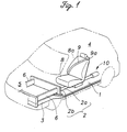
- Figure 1 is a perspective view showing an essential part of an automotive vehicle body embodying the present invention.
- a moveable part 2 serving as a first member is placed on a main frame 1 serving as a second member in such a manner that the moveable part 2 can move with respect to the main frame 1 in a direction of an input crash load when a vehicle crash takes place.
- the main frame 1 is integrally attached to an upper surface of a pair of first side beams 3 extending from the front end to the rear end of the vehicle body on either side of the vehicle body to serve as an energy absorbing part, and comprises a floor section of a passenger compartment 4 and a front section extending upward from the floor section to the lower edge of the front windshield at the boundary between the passenger compartment 4 and a bonnet room 5.
- the moveable part 2 comprises a rod portion (or piston) 2a extending in the fore-and-aft direction of the vehicle body and provided on the floor section of the main frame 1, and an upright portion 2b extending upward from a forward end of the rod portion 2a.
- a pair of second side beams 6 integrally extend from the front side of the upright portion 2b.
- the second side beams 6 extend in the fore-and-aft direction of the vehicle body substantially in parallel with the first side beams 3, and have forward ends which substantially align with the forward ends of the first side beams 3.
- the second side beams 6 are designed such that they are less deformable than the first side beams 3 in the event of a vehicle crash.
- a seat 8 is mounted on the rod portion 2a of the moveable part 2, and is fitted with a seat belt 9 as a restraint system.
- the seat belt 9 is provided with a shoulder anchor point 9a which is attached to an upper end portion of a seat back 8a.
- a support structure consisting of rails and sliders is provided between the seat 8 and the floor part of the main frame 1 to allow the fore-and-aft movement of the seat 8 although it is not shown in the drawings.
- a shoulder portion 2c is formed in an intermediate part of the rod portion 2a, and the abutting of the shoulder portion 2c onto an open end 11a of the cylinder 11 determines the limit of the rearward movement of the rod portion 2a or the moveable part 2.
- the shoulder portion 2c and the open end 11a function as a stopper for limiting the rearward movement of the moveable part 2 relative to the main frame 1.
- a T-shaped hole 2d formed in the rod portion 2a and a hole 11b provided in the side wall of the cylinder 11 jointly form a vent valve for allowing the high pressure gas generated from the high pressure gas generating device 10 to be vented in a later part of an intermediate phase of a vehicle crash, as described in more detail hereinafter.
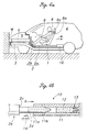
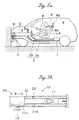
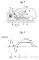
- Figure 4a is a side view similar to Figure 2 and shows an initial phase of a crash (the interval "a" in Figure 8).
- the front panel section of the outer body shell collapses, and the projecting front ends of the first side beams 3 and the second side beams 6 crash onto the object W immediately thereafter.
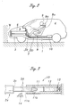
- the first side beams 3 collapse, producing a prescribed deceleration to the main frame 1, while the second side beams 6 which form the moveable part 2 experience less deformation than the first side beams 3, causing the moveable part 2 to start decelerating earlier at a deceleration level which builds up rapidly and sharply (solid line in Figure 8) than the main frame 1.
- the moveable part 2 apparently moves rearward (as indicated by arrow A in Figures 4a and 4b) relative to the main frame 1 which continues to move forward due to the compressive deformation of the first side beams 3.
- the vehicle occupant tends to continue to move forward under the inertial force, but because the seat 8 which is integral with the moveable part 2 instantly moves rearward with respect to the main frame 1, the restraining force of the seat belt 9 on the vehicle occupant increases, and the forward movement of the vehicle occupant is restrained.
- Figure 4b illustrates the positional relationship between the rod portion 2a of the moveable part 2 and the high pressure gas generating device 10 in the initial phase of the vehicle crash.
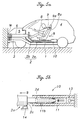
- the prescribed rearward displacement of the moveable part 2 with respect to the main frame 1 may be detected by any other appropriate detector than the limit switch 14, such as a pressure sensor for detecting a prescribed increase of the pressure inside the cylinder 11 resulting from the prescribed rearward displacement of the moveable part 2 relative to the main frame 1 (or more precisely, resulting from the progress of the rod portion 2a of the moveable part 2 into the cylinder 11). It may be also possible to use a fuse adapted to be activated by a prescribed high pressure development inside the cylinder 11 as the igniter 13, and omit the limit switch 14 to thereby simplify the configuration.
- a detector such as the limit switch 14 may be preferable in view of easy adjustment of the deceleration pattern of the seat depending on various conditions such as vehicle types or usage, since the ignition timing of the propellant 12 can be easily adjusted by varying the position of the limit switch 14 on the main frame 1.
- the high pressure gas inside the cylinder 11 is vented from the gas vent hole 2d of the rod 2a and the gas vent hole 11b of the cylinder 11 serving as a vent valve. Since the high pressure gas is vented through the gas vent holes 2d and 11b, it can be prevented that the high pressure gas inside the cylinder 11 undesirably affects the integral deceleration of the moveable part 2 and the main frame 1.
- the moveable part 2 (and hence the seat 8) is integral with the main frame 1 and the restraining load of the seat belt 9 balances out with the deceleration level of the seat 8, and thus the vehicle occupant is in a so-called “ride down state" with respect to the vehicle body, or the vehicle body deceleration and the vehicle occupant deceleration are substantially equal to each other (the interval "c" in Figure 8).
- This state is maintained until the vehicle body comes to a complete stop.
- the first side beams 3 and the second side beams 6 both progressively collapse at the same time, and jointly absorb the impact energy while decelerating the vehicle body.
- a passenger automobile is typically fitted with a pair of seats 8 which are arranged on either side of the vehicle body.
- the two seats 8 may be mounted on separate moveable parts 2 each connected to an associated high pressure gas generating device 7, and the two seats 8 may not be joined integrally to each other.
- the seat is subjected to a deceleration greater than an average deceleration in an early stage of a vehicle crash by causing a moveable part which is moveable in the fore-and-aft direction with respect to the vehicle body and is connected to the seat to move in a rearward direction, and, after a certain time delay, a negative deceleration (acceleration) is temporarily produced in the seat by applying a forward acceleration to the moveable part with a power generating device before the entire vehicle body finally decelerates at the average deceleration.
- a vehicle body (seat) deceleration waveform which is favorable for the deceleration of the vehicle occupant can be achieved, and the peak of the vehicle occupant deceleration can be substantially reduced with a smaller vehicle body deformation (dynamic stroke) than has been hitherto possible. Also, because this can be accomplished with a simple arrangement, a compact design of the vehicle body is possible.
- the displacement of the vehicle occupant in the passenger compartment (with respect to the vehicle body) can be reduced even further than the arrangement in which a restraint system is fitted with a load limiter to reduce the vehicle occupant deceleration, and thus the possibility of secondary crashes is also reduced.
- the vehicle occupant protection system can significantly reduce the peak deceleration of the vehicle occupant even with a small vehicle body.
- the seat is accelerated rearward upon the occurrence of a vehicle crash by the first member resisting deformation while the second member deforms so that the restraining capability of the seat belt is enhanced. Thereafter, an acceleration in the opposite direction is applied to the seat by the application of the forward force to the seat relative to the vehicle body so that the equalization of the decelerations of the vehicle body and the vehicle occupant is achieved in an early stage of the crash.
Landscapes
- Engineering & Computer Science (AREA)
- Aviation & Aerospace Engineering (AREA)
- Transportation (AREA)
- Mechanical Engineering (AREA)
- Automotive Seat Belt Assembly (AREA)
- Air Bags (AREA)
- Body Structure For Vehicles (AREA)
- Seats For Vehicles (AREA)
Claims (8)
- Système de protection des occupants d'un véhicule, comprenant :caractérisé en ce que ledit premier élément (2) est adapté pour se déformer sous la charge de l'accident tout en supportant la charge d'inertie dudit siège (8) lors de la survenue de l'accident du véhicule, en ce que ledit second élément (1) est adapté pour se déformer sous la charge de l'accident tout en supportant la force d'inertie du corps de véhicule, et en ce que ledit premier élément (2) est adapté pour se déformer essentiellement uniquement après que ladite force vers l'avant a été appliquée audit premier élément (2) par ledit mécanisme de commande de puissance (10) lors de la survenue de l'accident du véhicule.un siège (8) qui comporte une ceinture de siège (9) destinée à retenir un occupant d'un véhicule sur le siège (8) ;un premier élément (2) fixé sur le siège (8) et supporté sur un corps de véhicule de manière à pouvoir coulisser dans une direction de charge d'entrée d'accident résultant d'un accident d'un véhicule, le premier élément (2) supportant une force d'inertie dudit siège (8) lors de la survenue d'un accident du véhicule ;un second élément (1) qui est connecté à une partie principale du corps de véhicule et qui supporte une force d'inertie du corps de véhicule ; etun mécanisme de commande de puissance (10) destiné à appliquer une force vers l'avant sur ledit premier élément (2) par rapport audit second élément (1) avec une certaine temporisation après la survenue de l'accident du véhicule,
- Système de protection des occupants d'un véhicule selon la revendication 1, dans lequel ledit mécanisme de commande de puissance (10) comprend un cylindre (11), un piston (2a) reçu dans ledit cylindre (11) afin de définir une chambre close en coopération avec ledit cylindre (11), et un agent propulseur (12) qui est reçu dans ladite chambre et qui est adapté pour produire un gaz sous haute pression lors de l'allumage.
- Système de protection des occupants d'un véhicule selon la revendication 2, dans lequel un dispositif d'arrêt (2c, 11a) est disposé entre lesdits premier et second éléments (2, 1) afin de connecter intégralement l'un à l'autre lesdits deux éléments (2, 1) suivant un déplacement vers l'arrière prescrit dudit premier élément (2) par rapport audit second élément (1) lors de la survenue d'un accident du véhicule, et dans lequel ledit mécanisme de commande (10) comporte un clapet de purge (2d, 11b) destiné à expulser ledit gaz sous haute pression de ladite chambre lorsque ledit premier élément (2) a été connecté audit second élément (1) par ledit dispositif d'arrêt (2c, 11a).
- Système de protection des occupants d'un véhicule selon la revendication 3, dans lequel ledit dispositif d'arrêt (2c, 11a) est disposé entre une partie (2c) dudit piston (2a) et une extrémité dudit cylindre (11), et dans lequel ledit clapet de purge (2d, 11b) est formé entre une partie dudit piston (2a) et ledit cylindre (11).
- Système de protection des occupants d'un véhicule selon la revendication 2, comprenant en outre un détecteur (14) destiné à détecter un déplacement vers l'arrière prescrit dudit premier élément (2) par rapport audit second élément (1) lors de la survenue d'un accident du véhicule, et un allumeur (13) destiné à allumer ledit agent propulseur (12) en fonction d'un signal en provenance dudit détecteur (14).
- Système de protection des occupants d'un véhicule selon la revendication 5, dans lequel ledit détecteur (14) comprend un contacteur de fin de course.
- Système de protection des occupants d'un véhicule selon la revendication 5, dans lequel ledit détecteur comprend un capteur de pression destiné à détecter une augmentation de pression à l'intérieur dudit cylindre (11) résultant dudit déplacement vers l'arrière prescrit dudit premier élément (2) par rapport audit second élément (1) lors de la survenue d'un accident du véhicule.
- Système de protection des occupants d'un véhicule selon la revendication 2, dans lequel un dispositif d'arrêt (2c, 11a) est disposé entre lesdits premier et second éléments (2, 1) afin de connecter intégralement lesdits deux éléments (2, 1) l'un à l'autre suivant un premier déplacement vers l'arrière prescrit dudit premier élément (2) par rapport au dit second élément (1) lors de la survenue d'un accident du véhicule, et dans lequel ledit mécanisme de commande (10) comporte un clapet de purge (2d, 11b) destiné à expulser ledit gaz sous haute pression de ladite chambre lorsque ledit premier élément (2) a été connecté au dit second élément (1) par ledit dispositif d'arrêt (2c, 11a), et dans lequel,
ledit système comprend en outre :un détecteur destiné à détecter un second déplacement vers l'arrière prescrit dudit premier élément (2) par rapport au dit second élément (1) lors de la survenue d'un accident du véhicule, ledit second déplacement vers l'arrière prescrit étant plus petit que ledit premier déplacement vers l'arrière prescrit ; etun allumeur (13) destiné à allumer ledit agent propulseur (12) en fonction d'un signal en provenance dudit détecteur (14).
Applications Claiming Priority (2)
| Application Number | Priority Date | Filing Date | Title |
|---|---|---|---|
| JP19065999 | 1999-07-05 | ||
| JP11190659A JP2001018832A (ja) | 1999-07-05 | 1999-07-05 | 乗員保護装置 |
Publications (2)
| Publication Number | Publication Date |
|---|---|
| EP1067014A1 EP1067014A1 (fr) | 2001-01-10 |
| EP1067014B1 true EP1067014B1 (fr) | 2004-03-03 |
Family
ID=16261777
Family Applications (1)
| Application Number | Title | Priority Date | Filing Date |
|---|---|---|---|
| EP00114417A Expired - Lifetime EP1067014B1 (fr) | 1999-07-05 | 2000-07-05 | Système de protection des passagers d'un véhicule |
Country Status (4)
| Country | Link |
|---|---|
| US (1) | US6394535B1 (fr) |
| EP (1) | EP1067014B1 (fr) |
| JP (1) | JP2001018832A (fr) |
| DE (1) | DE60008640T2 (fr) |
Families Citing this family (24)
| Publication number | Priority date | Publication date | Assignee | Title |
|---|---|---|---|---|
| SE514294C2 (sv) * | 1998-09-30 | 2001-02-05 | Volvo Lastvagnar Ab | Anordning som möjliggör förskjutning av förarutrymmet hos ett fordon |
| US8251444B2 (en) * | 2005-04-25 | 2012-08-28 | Arjuna Indraeswaran Rajasingham | Vehicle occupant support |
| JP2001163137A (ja) * | 1999-12-06 | 2001-06-19 | Honda Motor Co Ltd | 乗員保護装置 |
| JP3904384B2 (ja) * | 2000-10-31 | 2007-04-11 | 本田技研工業株式会社 | 乗員保護装置 |
| SE522126C2 (sv) * | 2000-12-08 | 2004-01-13 | Volvo Lastvagnar Ab | Anordning för att försvaga en konstruktion |
| JP4350921B2 (ja) | 2001-06-12 | 2009-10-28 | 本田技研工業株式会社 | 乗員保護装置 |
| JP4621384B2 (ja) | 2001-07-18 | 2011-01-26 | 本田技研工業株式会社 | 乗員保護装置 |
| JP4448626B2 (ja) * | 2001-07-18 | 2010-04-14 | 本田技研工業株式会社 | 乗員保護装置 |
| JP2003089335A (ja) * | 2001-09-18 | 2003-03-25 | Honda Motor Co Ltd | 乗員保護装置 |
| DE10202984A1 (de) * | 2002-01-26 | 2003-08-07 | Porsche Ag | Aufbaustruktur eines Kraftfahrzeugs |
| JP2004188998A (ja) * | 2002-12-06 | 2004-07-08 | Honda Motor Co Ltd | 車体フレーム |
| DE102004029745B4 (de) * | 2004-06-19 | 2016-10-20 | Volkswagen Ag | Pralldämpfungsvorrichtung für ein Fahrzeug |
| US8136835B2 (en) * | 2005-07-21 | 2012-03-20 | Arjuna Indraeswaran Rajasingham | Easy ejector seat with skeletal crash safety beam |
| US7258392B2 (en) * | 2005-08-18 | 2007-08-21 | Ford Global Technologies, Llc | Automotive vehicle front architecture with a partially rotatable structural link |
| US7611197B2 (en) * | 2006-06-26 | 2009-11-03 | International Truck Intellectual Property Company, Llc | Occupant restraint passenger seat assembly with load-sensing energy absorption feature |
| DE102011101150A1 (de) * | 2011-05-11 | 2012-11-15 | Daimler Ag | Insassenschutzvorrichtung für ein Fahrzeug und Verfahren zum Schutz eines Insassen eines Fahrzeugs |
| CN103010055B (zh) * | 2013-01-18 | 2014-12-10 | 金陵科技学院 | 一种汽车用位置调节及防撞装置 |
| CN103802700B (zh) * | 2014-02-12 | 2016-04-13 | 吴双双 | 一种汽车座椅碰撞缓冲装置 |
| CN104260790A (zh) * | 2014-09-24 | 2015-01-07 | 安徽安凯汽车股份有限公司 | 一种客车驾驶员保护结构 |
| CN106043438B (zh) * | 2016-07-21 | 2018-05-25 | 郑州宇通客车股份有限公司 | 车架及使用该车架的车辆 |
| US11400839B2 (en) * | 2020-09-22 | 2022-08-02 | Ford Global Technologies, Llc | Energy absorbing vehicle seat |
| CN115158122B (zh) * | 2022-07-13 | 2023-09-22 | 黄淮学院 | 一种智能网联汽车座舱及其使用方法 |
| CN115923621A (zh) * | 2023-01-09 | 2023-04-07 | 深圳弘冉智能科技有限公司 | 能够适应不同的碰撞方向的乘员安全系统及其制备方法 |
| US12594863B1 (en) | 2025-07-21 | 2026-04-07 | Automotive Safety Research, Inc. | System for mitigating the severity of motor vehicle crashes |
Family Cites Families (41)
| Publication number | Priority date | Publication date | Assignee | Title |
|---|---|---|---|---|
| US2227563A (en) | 1938-08-11 | 1941-01-07 | Telefunken Gmbh | Directional antenna array |
| US3001815A (en) | 1958-02-25 | 1961-09-26 | Robert C Weber | Bumper actuated vehicle safety seat |
| US2959446A (en) | 1958-04-24 | 1960-11-08 | Thompson William Francis | Automobile crash absorbing construction |
| GB1043695A (en) | 1962-09-19 | 1966-09-21 | Nat Res Dev | Improvements in or relating to safety harness and like safety devices for occupants of vehicles |
| US3732944A (en) | 1971-04-12 | 1973-05-15 | Menasco Mfg Co | Automatic vacuum restraint apparatus |
| US3897101A (en) | 1973-05-18 | 1975-07-29 | Brose & Co Metallwerk Max | Driver{3 s seat with inertia-responsive locking arrangement |
| DE2344689A1 (de) | 1973-09-05 | 1975-03-13 | Porsche Ag | Sicherheitseinrichtung fuer kraftfahrzeuge |
| DE2416313C3 (de) | 1974-04-04 | 1978-11-23 | Roland 8731 Euerdorf Satzinger | Sicherheitseinrichtung für die Insassen von Fahrzeugen, insbesondere Kraftfahrzeugen |
| US3998291A (en) | 1975-08-06 | 1976-12-21 | Edwin George Davis | Automotive safety seat |
| CH612503A5 (fr) | 1977-05-13 | 1979-07-31 | Mettler Instrumente Ag | |
| DE3424928A1 (de) | 1984-07-06 | 1986-01-16 | Walter 8720 Schweinfurt Lindwurm | Schleudersitz - sicherheitsanlage fuer kraftfahrzeuge |
| US4832409A (en) | 1987-09-08 | 1989-05-23 | General Motors Corporation | Restraint belt load capacity fore and aft power seat adjuster apparatus |
| US4881781A (en) | 1987-09-08 | 1989-11-21 | General Motors Corporation | Restraint belt load capacity fore and aft power seat adjuster apparatus and method |
| US5286085A (en) | 1989-06-30 | 1994-02-15 | Takata Corporation | Restraining protective seat for infants |
| US5167421A (en) | 1990-07-16 | 1992-12-01 | Liu Yunzhao | Safety seat equipped in automobile |
| AU2460192A (en) | 1991-07-19 | 1993-02-23 | Massachusetts Institute Of Technology | Safety seat |
| JP3327297B2 (ja) | 1992-02-26 | 2002-09-24 | マツダ株式会社 | 車両の衝撃コントロール構造及び衝撃コントロール方法 |
| JPH05246252A (ja) | 1992-03-04 | 1993-09-24 | Toyota Motor Corp | 電気自動車のバッテリ固定構造 |
| JP2866998B2 (ja) | 1992-03-04 | 1999-03-08 | トヨタ自動車株式会社 | 電気自動車のバッテリ固定構造 |
| US5437494A (en) | 1992-10-29 | 1995-08-01 | Life Force Associates, L.P. | Rearward moving seat |
| DE4345185C2 (de) | 1993-03-31 | 1995-03-23 | Mueller Franz Dipl Ing Fh | Verfahren zum Verringern der bei einem Aufprall eines Fahrzeugs auf ein Hindernis auf einen auf einem Sitz angegurteten Fahrzeuginsassen einwirkenden Kräfte unter Verwendung von Airbags |
| US5409262A (en) | 1993-08-31 | 1995-04-25 | Mclennan; Ronald A. | Vehicle safety system |
| JPH07101354A (ja) | 1993-10-05 | 1995-04-18 | Isuzu Motors Ltd | 車両用サイドメンバ |
| JPH07205733A (ja) | 1994-01-20 | 1995-08-08 | Kunihiro Hasegawa | 車両安全機構 |
| DE4415467C1 (de) * | 1994-05-03 | 1995-11-23 | Daimler Benz Ag | Sicherheitseinrichtung für Fahrzeuge |
| US5681057A (en) | 1995-02-17 | 1997-10-28 | U.S. Electricar | Crash energy-management structure |
| US5810417A (en) | 1995-09-28 | 1998-09-22 | Mongkol Jesadanont | Automatic safety car seats and sheet-type safety-belt |
| US5626203A (en) | 1995-11-01 | 1997-05-06 | Habib; Mostafa S. | Active control of a vehicle occupant's body in frontal collision |
| GB9525033D0 (en) | 1995-12-07 | 1996-02-07 | Henlys Group Plc | Safety seat |
| US5685603A (en) | 1996-03-05 | 1997-11-11 | Trw Vehicle Safety Systems Inc. | Apparatus with a child seat and an energy absorption mechanism |
| WO1998040238A1 (fr) | 1997-03-11 | 1998-09-17 | Kent Nilsson | Protection contre le coup du lapin |
| US5947543A (en) * | 1997-04-03 | 1999-09-07 | Hubbard; Leo James | Vehicle safety system |
| US6092853A (en) * | 1997-04-03 | 2000-07-25 | Hubbard; Leo James | Vehicle safety system |
| US6042190A (en) | 1997-09-19 | 2000-03-28 | Daimlerchrysler Ag | Vehicle seat |
| JP2000062557A (ja) | 1998-08-20 | 2000-02-29 | Honda Motor Co Ltd | 乗員保護装置 |
| JP3459776B2 (ja) | 1998-08-20 | 2003-10-27 | 本田技研工業株式会社 | 乗員保護装置 |
| US6116561A (en) | 1998-08-28 | 2000-09-12 | Lear Corporation | Method and apparatus for seat track construction |
| US6170865B1 (en) | 1999-01-23 | 2001-01-09 | Martin Barron | Electromagnetic car seat release upon deployment of vehicular air bag |
| JP2001039249A (ja) | 1999-07-30 | 2001-02-13 | Honda Motor Co Ltd | 自動車の車体構造 |
| US6224131B1 (en) | 1999-09-21 | 2001-05-01 | Mohammad Shammout | Reactive seat system |
| US6227597B1 (en) | 1999-09-27 | 2001-05-08 | Trw Inc. | Vehicle seat with limited rearward movement |
-
1999
- 1999-07-05 JP JP11190659A patent/JP2001018832A/ja active Pending
-
2000
- 2000-06-30 US US09/608,669 patent/US6394535B1/en not_active Expired - Fee Related
- 2000-07-05 EP EP00114417A patent/EP1067014B1/fr not_active Expired - Lifetime
- 2000-07-05 DE DE60008640T patent/DE60008640T2/de not_active Expired - Fee Related
Also Published As
| Publication number | Publication date |
|---|---|
| EP1067014A1 (fr) | 2001-01-10 |
| JP2001018832A (ja) | 2001-01-23 |
| US6394535B1 (en) | 2002-05-28 |
| DE60008640D1 (de) | 2004-04-08 |
| DE60008640T2 (de) | 2005-02-24 |
Similar Documents
| Publication | Publication Date | Title |
|---|---|---|
| EP1067014B1 (fr) | Système de protection des passagers d'un véhicule | |
| US6193296B1 (en) | Vehicle occupant protection system | |
| US6186574B1 (en) | Vehicle occupant protection system | |
| JP3904384B2 (ja) | 乗員保護装置 | |
| US6863308B2 (en) | Automotive vehicle occupant protection system | |
| EP1266792B1 (fr) | Système de protection de choc latéral pour passager de véhicule | |
| US6843504B2 (en) | Automotive vehicle occupant protection system | |
| JP2001163135A (ja) | 乗員保護装置 | |
| EP1078812B1 (fr) | Système de protection des occupants d'un véhicule | |
| EP1072464B1 (fr) | Système de protection des passagers d'un véhicule | |
| EP1266809B1 (fr) | Syteme de protection pour les occupants d'un véhicule automobile | |
| EP1203700B1 (fr) | Système de protection pour occupant d'un véhicule | |
| EP1070657B1 (fr) | Structure de chassis de véhicule automobile | |
| US6578894B2 (en) | Automotive vehicle occupant protection system | |
| JP2002145013A (ja) | 乗員保護装置 | |
| JP2003025889A (ja) | 乗員保護装置 | |
| JP4430966B2 (ja) | 乗員保護装置 | |
| JP2005263154A (ja) | 乗員保護装置 | |
| JP2001163175A (ja) | 乗員保護装置 |
Legal Events
| Date | Code | Title | Description |
|---|---|---|---|
| PUAI | Public reference made under article 153(3) epc to a published international application that has entered the european phase |
Free format text: ORIGINAL CODE: 0009012 |
|
| AK | Designated contracting states |
Kind code of ref document: A1 Designated state(s): DE FR GB |
|
| AX | Request for extension of the european patent |
Free format text: AL;LT;LV;MK;RO;SI |
|
| 17P | Request for examination filed |
Effective date: 20010117 |
|
| AKX | Designation fees paid |
Free format text: DE FR GB |
|
| 17Q | First examination report despatched |
Effective date: 20030120 |
|
| GRAP | Despatch of communication of intention to grant a patent |
Free format text: ORIGINAL CODE: EPIDOSNIGR1 |
|
| GRAS | Grant fee paid |
Free format text: ORIGINAL CODE: EPIDOSNIGR3 |
|
| GRAA | (expected) grant |
Free format text: ORIGINAL CODE: 0009210 |
|
| AK | Designated contracting states |
Kind code of ref document: B1 Designated state(s): DE FR GB |
|
| REG | Reference to a national code |
Ref country code: GB Ref legal event code: FG4D |
|
| REF | Corresponds to: |
Ref document number: 60008640 Country of ref document: DE Date of ref document: 20040408 Kind code of ref document: P |
|
| ET | Fr: translation filed | ||
| PLBE | No opposition filed within time limit |
Free format text: ORIGINAL CODE: 0009261 |
|
| STAA | Information on the status of an ep patent application or granted ep patent |
Free format text: STATUS: NO OPPOSITION FILED WITHIN TIME LIMIT |
|
| 26N | No opposition filed |
Effective date: 20041206 |
|
| PGFP | Annual fee paid to national office [announced via postgrant information from national office to epo] |
Ref country code: GB Payment date: 20050629 Year of fee payment: 6 |
|
| PGFP | Annual fee paid to national office [announced via postgrant information from national office to epo] |
Ref country code: DE Payment date: 20050630 Year of fee payment: 6 |
|
| PGFP | Annual fee paid to national office [announced via postgrant information from national office to epo] |
Ref country code: FR Payment date: 20050708 Year of fee payment: 6 |
|
| PG25 | Lapsed in a contracting state [announced via postgrant information from national office to epo] |
Ref country code: GB Free format text: LAPSE BECAUSE OF NON-PAYMENT OF DUE FEES Effective date: 20060705 |
|
| PG25 | Lapsed in a contracting state [announced via postgrant information from national office to epo] |
Ref country code: DE Free format text: LAPSE BECAUSE OF NON-PAYMENT OF DUE FEES Effective date: 20070201 |
|
| GBPC | Gb: european patent ceased through non-payment of renewal fee |
Effective date: 20060705 |
|
| REG | Reference to a national code |
Ref country code: FR Ref legal event code: ST Effective date: 20070330 |
|
| PG25 | Lapsed in a contracting state [announced via postgrant information from national office to epo] |
Ref country code: FR Free format text: LAPSE BECAUSE OF NON-PAYMENT OF DUE FEES Effective date: 20060731 |