EP1067275A2 - Tendeur de chaíne hydraulique avec dispositif directionnel de décharge d'air - Google Patents
Tendeur de chaíne hydraulique avec dispositif directionnel de décharge d'air Download PDFInfo
- Publication number
- EP1067275A2 EP1067275A2 EP00305430A EP00305430A EP1067275A2 EP 1067275 A2 EP1067275 A2 EP 1067275A2 EP 00305430 A EP00305430 A EP 00305430A EP 00305430 A EP00305430 A EP 00305430A EP 1067275 A2 EP1067275 A2 EP 1067275A2
- Authority
- EP
- European Patent Office
- Prior art keywords
- vent
- chain tensioner
- plunger
- chamber
- fluid
- Prior art date
- Legal status (The legal status is an assumption and is not a legal conclusion. Google has not performed a legal analysis and makes no representation as to the accuracy of the status listed.)
- Granted
Links
Images


Classifications
-
- F—MECHANICAL ENGINEERING; LIGHTING; HEATING; WEAPONS; BLASTING
- F16—ENGINEERING ELEMENTS AND UNITS; GENERAL MEASURES FOR PRODUCING AND MAINTAINING EFFECTIVE FUNCTIONING OF MACHINES OR INSTALLATIONS; THERMAL INSULATION IN GENERAL
- F16H—GEARING
- F16H7/00—Gearings for conveying rotary motion by endless flexible members
- F16H7/08—Means for varying tension of belts, ropes or chains
- F16H7/0829—Means for varying tension of belts, ropes or chains with vibration damping means
- F16H7/0836—Means for varying tension of belts, ropes or chains with vibration damping means of the fluid and restriction type, e.g. dashpot
-
- F—MECHANICAL ENGINEERING; LIGHTING; HEATING; WEAPONS; BLASTING
- F01—MACHINES OR ENGINES IN GENERAL; ENGINE PLANTS IN GENERAL; STEAM ENGINES
- F01L—CYCLICALLY OPERATING VALVES FOR MACHINES OR ENGINES
- F01L1/00—Valve-gear or valve arrangements, e.g. lift-valve gear
- F01L1/02—Valve drive
-
- F—MECHANICAL ENGINEERING; LIGHTING; HEATING; WEAPONS; BLASTING
- F01—MACHINES OR ENGINES IN GENERAL; ENGINE PLANTS IN GENERAL; STEAM ENGINES
- F01L—CYCLICALLY OPERATING VALVES FOR MACHINES OR ENGINES
- F01L1/00—Valve-gear or valve arrangements, e.g. lift-valve gear
- F01L1/02—Valve drive
- F01L1/022—Chain drive
-
- F—MECHANICAL ENGINEERING; LIGHTING; HEATING; WEAPONS; BLASTING
- F01—MACHINES OR ENGINES IN GENERAL; ENGINE PLANTS IN GENERAL; STEAM ENGINES
- F01L—CYCLICALLY OPERATING VALVES FOR MACHINES OR ENGINES
- F01L1/00—Valve-gear or valve arrangements, e.g. lift-valve gear
- F01L1/02—Valve drive
- F01L1/024—Belt drive
-
- F—MECHANICAL ENGINEERING; LIGHTING; HEATING; WEAPONS; BLASTING
- F16—ENGINEERING ELEMENTS AND UNITS; GENERAL MEASURES FOR PRODUCING AND MAINTAINING EFFECTIVE FUNCTIONING OF MACHINES OR INSTALLATIONS; THERMAL INSULATION IN GENERAL
- F16H—GEARING
- F16H7/00—Gearings for conveying rotary motion by endless flexible members
- F16H7/08—Means for varying tension of belts, ropes or chains
- F16H2007/0802—Actuators for final output members
- F16H2007/0806—Compression coil springs
-
- F—MECHANICAL ENGINEERING; LIGHTING; HEATING; WEAPONS; BLASTING
- F16—ENGINEERING ELEMENTS AND UNITS; GENERAL MEASURES FOR PRODUCING AND MAINTAINING EFFECTIVE FUNCTIONING OF MACHINES OR INSTALLATIONS; THERMAL INSULATION IN GENERAL
- F16H—GEARING
- F16H7/00—Gearings for conveying rotary motion by endless flexible members
- F16H7/08—Means for varying tension of belts, ropes or chains
- F16H2007/0802—Actuators for final output members
- F16H2007/0812—Fluid pressure
- F16H2007/0814—Fluid pressure with valves opening on surplus pressure
-
- F—MECHANICAL ENGINEERING; LIGHTING; HEATING; WEAPONS; BLASTING
- F16—ENGINEERING ELEMENTS AND UNITS; GENERAL MEASURES FOR PRODUCING AND MAINTAINING EFFECTIVE FUNCTIONING OF MACHINES OR INSTALLATIONS; THERMAL INSULATION IN GENERAL
- F16H—GEARING
- F16H7/00—Gearings for conveying rotary motion by endless flexible members
- F16H7/08—Means for varying tension of belts, ropes or chains
- F16H7/0848—Means for varying tension of belts, ropes or chains with means for impeding reverse motion
- F16H2007/0859—Check valves
Definitions
- the invention relates to a hydraulic chain tensioner for use with an associated chain or belt that drives an engine camshaft, balance shaft drive or the like.
- the hydraulic tensioner of the present invention is directed to an improvement of the construction of a hydraulic tensioner to prevent errors in the assembly of the vent device.
- a hydraulic tensioner in general, includes a housing, a plunger inserted into a bore formed in the housing, and a spring that biases the plunger in the projecting or protruding direction.
- a chamber is formed by assembling a hollow plunger into the bore of the housing. Oil is supplied to the chamber from an external oil pressure source. The pressurized oil acts on the plunger to cause the plunger to protrude from the housing bore and provide tension to an associated chain.
- the plunger when air mixes with oil in the chamber, the plunger can be forced inwardly toward the housing due to compression of the mixed air and oil.
- the air/oil mixture compresses when the tension of the chain or belt increases and, as a result, the chain or belt tension can vary due to the reduced effectiveness of the tensioner.
- a hydraulic tensioner as disclosed in Japanese Laid-Open Patent No. 7-158703, discloses one proposed solution of such a problem.
- This hydraulic tensioner has a disc as a vent device inside the plunger.
- a spiral groove is formed on the disc surface. The starting end of the groove is located on the outer peripheral side of the disc surface and the terminal end is located at the center of the disc surface.
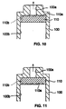
- FIG. 10 shows the enlarged plunger tip portion of the hydraulic tensioner disclosed in the above-mentioned prior art patent publication.
- a hole 100a is formed at the tip of plunger 100 and disc 110 is inserted in inner chamber 100b formed inside hollow plunger 100.
- Spiral groove 110a is formed on one of the main surfaces (top surface) of disc 110.
- a groove 110b is formed that extends in the direction of the center axis of the plunger and connects to the starting end of groove 110a.
- product inspection after assembly of the hydraulic tensioner involves checking the ability of the chamber to retain oil pressure by introducing hydraulic oil into the chamber and measuring the rate of leakage of oil from the hole at the plunger tip.
- a disc 110 that functions as a vent device is in a single round plate shape, so that, as shown in FIG. 11, disc 110 can be assembled in an up/down reversed fashion.
- air mixed into the chamber cannot be discharged outside of the tensioner because spiral groove 110a of disc 110 is not connected to hole 100a of plunger 100.
- the hydraulic oil in the chamber can pass groove 110b on the outer periphery of disc 110, pass through the gap between the disc's main surface and the plunger and leak out of the tensioner. The product can be judged to be acceptable, even in such case of incorrect assembly.
- the objective of this invention is to offer a hydraulic tensioner that prevents incorrect assembly of the vent device and that eliminates such a conventional problem.
- It is a first object of the present invention to provide a hydraulic chain tensioner including a housing with a bore formed therein.
- a hollow plunger is inserted slidably into the housing.
- the plunger has a tip with an open vent hole or aperture and a spring member that biases the plunger in the protruding direction.
- a vent device or disc is provided inside the hollow portion of the plunger.
- the vent device is composed of disc first and second portions.
- the first portion has a first main surface on which the vent channel is formed and the said second portion is provided on the second main surface which is on the opposite side to the first main surface.
- the second portion has a passage, the outer diameter of which is larger than the open vent hole in the plunger that connects to a hole in the center axis direction and extends to intersect the center axis and opens on the outer peripheral surface.
- the vent device is assembled into the plunger with the first main surface having a vent channel facing toward the tip of the plunger.
- fluid in the chamber passes the vent channel on the first main surface of the vent device, passes the open hole at the plunger tip and is discharged from the tensioner if fluid in the chamber is pressurized during product inspection.
- Air mixed in the chamber passes the vent channel on the first main surface of the vent device and leaks out to the outside air from the hole at the plunger tip.
- the fluid in the chamber flows into the passage from its opening on the outer surface of the second portion of the vent device, passes the hole in the center axis direction and is discharged in a large quantity to the outside of the tensioner.
- the volume of fluid discharged from the hole at the plunger tip is large when incorrectly assembled, so that it can be separated from correctly assembled devices and, thereby, erroneous assembly of the vent device can be prevented.
- the outer diameter of the first portion of the vent device is slightly smaller than the inner diameter of the plunger, so that a gap is formed between the outer diameter of the first portion of the vent device and the inner diameter of the plunger, and, thereby, the air mixed in the chamber passes the gap and moves to the side of the first main surface of the vent device and is discharged outside of the vent channel on the first main surface.
- the outer diameter of the first portion of the vent device is substantially equal to the inner diameter of the plunger, so that when the vent device is assembled into the plunger, the outer diameter of the first portion of the vent device fits the inner diameter of the plunger without clearance.
- An axial groove connected to the starting end of the vent channel is formed on the outer periphery of the first portion of the vent device. Therefore, the air mixed in the chamber moves to the side of the first main surface of the vent device through the groove and is discharged outside from the vent channel on the first main surface.
- the vent channel may be circuitous from the starting end to the terminal end so that flow of liquid leaking from the chamber is restricted and the leak volume is suppressed.
- Other shapes of vent channels are contemplated including a spiral-shaped vent channel or a vent channel composed of multiple linear portions that bend at least 90 degrees.
- the passage opening on the outer periphery of the second portion of the vent device can be a groove formed on the end face of the second portion.
- the vent device is pushed toward the plunger tip by the force of the spring. Thereby, the first main surface of the vent device can be contacted closely with the inner wall of the plunger tip during correct assembly.
- the vent device has a through-hole that connects to the center hole of the second portion, at the center of the first portion of the vent device. The vent device is assembled onto the pressure relief valve assembly and the pressure relief valve assembly is pushed toward the plunger tip by the spring. At the same time, a through-hole, that connects to the axial hole of the second portion, is formed at the center of the first portion of the vent device.
- the outer diameter of the second portion of the vent device is inserted into the hole formed on one end of the pressure relief valve assembly, so that the hydraulic tensioner can be made more compact.
- a passage to connect the chamber to the external pressurized fluid source is provided in the housing so that the fluid from the external pressurized fluid source is supplied to the chamber through this passage.
- a check valve is provided between the chamber and passage so that the flow of fluid to inside the chamber from the pressurized fluid source is permitted, but meanwhile, the reverse flow of fluid is blocked.
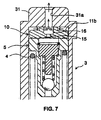
- hydraulic tensioner 1 includes housing 2 having a hollow plunger 3 inserted slidably into bore 2a in housing 2 and spring 4, that urges or biases plunger 3 in the protruding direction from bore 2a.
- chamber 20 is formed by the inner wall of bore 2a and the hollow plunger 3. Open hole 31a is formed at the center of tip 31 of plunger 3.
- a ball check valve 6 is provided on the bottom wall of the chamber inside housing 2. This ball check valve 6 permits fluid to flow into the chamber 20, but blocks the reverse flow of fluid. Passage 7 that connects chamber 20 to the external pressurized fluid source P is formed in housing 2.
- a pressure relief valve assembly 5 is provided on the side of tip 31 inside plunger 3. This pressure relief valve assembly 5 permits the fluid from chamber 20 to exit the tensioner chamber when the fluid pressure inside chamber 20 exceeds a set maximum value.
- Air vent disc 10 as a vent device, is integrally assembled into pressure relief valve assembly 5.
- the force of spring 4 acts on plunger 3 via pressure relief valve 5 and air vent disc 10.
- Pressure relief valve assembly 5, air vent disc 10 and plunger tip 31 are in close mutual contact because of the force of spring 4.
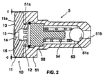
- FIG. 2 shows an enlargement of pressure relief valve assembly 5 and air vent disc 10.
- pressure relief valve assembly 5 includes valve housing 51 with apertures 51a and 51b on both ends and plug member 52, fixed to the inside of valve housing 51, ball 53, that can contact seat 51c formed in valve housing 51, and valve spring 54 that urges ball 53 onto seat 51c.
- air vent disc 10 has disc-shaped first and second portions, 11 and 12.
- Spiral groove 13 is formed on main surface 11a of first portion 11 and acts as a vent channel (see FIG. 5).
- starting end 13a of groove 13 narrows toward its tip and its terminal end 13b is connected to countersunk hole 14 at the center.
- Through-hole 15 that connects countersunk hole 14 is formed at the center of first portion 11.
- the second portion 12 of air vent disc 10 is provided on main surface 11a of first portion 11 and opposite main surface 11b.
- second portion 12 of air vent disc 10 is inserted into open hole 51a of valve housing 51 of pressure relief valve assembly 5 and thereby its entirety is constructed in a compact manner.
- the outer diameter d (FIG. 4) of the second portion 12 is larger than the inner diameter of open hole 31a at plunger tip 31.
- Hole 16 that connects to through-hole 15 of the first portion is formed at the center of second portion 12.
- multiple grooves 17 are formed on the end face of second portion 12 and define channels that open on the outer periphery of second portion 12 and that connect to hole 16 and extend radially.
- Outer diameter D of first portion 11 of air vent disc 10 (FIG. 4) is slightly smaller than the hole diameter of plunger 3 and, as shown in FIG. 2, a clearance c is formed between it and the plunger inner wall, when it is assembled into plunger 3.
- plunger 3 is urged in a projecting direction from the housing bore because of the fluid pressure inside chamber 20 and the force of spring 4. Tip 31 contacts an associated chain (not shown) so that a tension is applied to the chain. At such time, the force acting on plunger 3 from the chain and toward the inside of the housing is balanced with the outward force due to spring 4 and the fluid pressure inside chamber 20.
- the fluid in chamber 20 passes through the gap between the inner diameter of plunger 3 and the outer diameter of air vent disc 10 and flows into groove 17 from the aperture on the outer periphery of second portion 12 of air vent disc 10 and passes through axial hole 16, through-hole 15 and countersunk hole 14, to be discharged in large quantity to the outside of the tensioner from open hole 31a at plunger tip 31.
- outer diameter D of first portion 11 of air vent disc 10 is slightly smaller than the hole diameter of plunger 3, but outer diameter D of first portion 11 of air vent disc 10 can be substantially equal to the hole diameter of plunger 3 and grooves can be formed on the outer periphery of first portion 11, to extend in the direction of the center axis.
- first portion 11 of air vent disc 10 fits with the inner diameter of plunger 3 without clearance.
- the mixed-in air in chamber 20 passes through the groove on the outer periphery of first portion 11 and moves to the side of first main surface 11a of air vent disc 10, to be discharged to the outside past the vent channel on first main surface 11a.
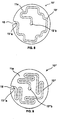
- the vent channel is a spiral groove 13, but groove 13 is not limited to a spiral shape and, as shown in FIGS. 8 and 9, it can be composed of multiple linear portions with at least a 90 degree bend.
- FIGS. 8 and 9 the same or equivalent elements are assigned the same reference characters.
- groove 13' is composed of multiple linear portions with 90 degree bending from its starting end 13'a to its terminal end 13'b.
- Groove 18 in the axial direction (vertical to the paper surface), that connects to starting end 13'a of groove 13' is formed on the outer periphery of air vent disc 10'.
- groove 13'' is composed of multiple linear portions with 90 degree and 180 degree bending from its starting end 13''a to its terminal end 13''b.
- Groove 18, the same as that in FIG. 8, is formed on the outer periphery of air vent disc 10'.
- the mixed-in air in chamber 3 is discharged to the outside of the tensioner by flowing through groove 13' or 13'' on the side of main surface 11a from groove 18 on the outer periphery of the air vent disc.
- a vent device is provided inside a hollow plunger.
- the vent device includes a first portion having a vent channel and a second portion having an outer diameter that is larger than the aperture at the plunger tip, an axial hole and a channel that opens on the outer periphery.
Landscapes
- Engineering & Computer Science (AREA)
- General Engineering & Computer Science (AREA)
- Mechanical Engineering (AREA)
- Devices For Conveying Motion By Means Of Endless Flexible Members (AREA)
Applications Claiming Priority (2)
| Application Number | Priority Date | Filing Date | Title |
|---|---|---|---|
| JP19121899 | 1999-07-06 | ||
| JP11191218A JP2001021013A (ja) | 1999-07-06 | 1999-07-06 | 液圧テンショナ |
Publications (3)
| Publication Number | Publication Date |
|---|---|
| EP1067275A2 true EP1067275A2 (fr) | 2001-01-10 |
| EP1067275A3 EP1067275A3 (fr) | 2001-09-26 |
| EP1067275B1 EP1067275B1 (fr) | 2005-09-07 |
Family
ID=16270878
Family Applications (1)
| Application Number | Title | Priority Date | Filing Date |
|---|---|---|---|
| EP00305430A Expired - Lifetime EP1067275B1 (fr) | 1999-07-06 | 2000-06-28 | Tendeur de chaíne hydraulique avec dispositif directionnel de décharge d'air |
Country Status (4)
| Country | Link |
|---|---|
| US (1) | US6352487B1 (fr) |
| EP (1) | EP1067275B1 (fr) |
| JP (1) | JP2001021013A (fr) |
| DE (1) | DE60022439T2 (fr) |
Cited By (5)
| Publication number | Priority date | Publication date | Assignee | Title |
|---|---|---|---|---|
| EP1498580A3 (fr) * | 2003-07-16 | 2006-05-31 | Renold Plc | Tendeur pour chaîne ou courroie |
| US7634949B2 (en) | 2005-07-23 | 2009-12-22 | Renold Plc | Transmission chain monitoring system |
| RU2436002C2 (ru) * | 2009-05-05 | 2011-12-10 | Сергей Григорьевич Куделин | Гидромеханическое устройство для натяжения цепи |
| CN101799063B (zh) * | 2009-02-10 | 2012-06-06 | 超汇桂盟传动(苏州)有限公司 | 液压张紧装置 |
| DE102011013374A1 (de) * | 2011-03-09 | 2012-09-13 | Iwis Motorsysteme Gmbh & Co. Kg | Spannvorrichtung mit mindestens zwei Entlüftungselementen |
Families Citing this family (33)
| Publication number | Priority date | Publication date | Assignee | Title |
|---|---|---|---|---|
| JP3670911B2 (ja) * | 1999-11-19 | 2005-07-13 | Ntn株式会社 | チェーンテンショナ |
| JP3322398B2 (ja) * | 1999-12-27 | 2002-09-09 | 株式会社椿本チエイン | リリーフバルブ付油圧式テンショナ |
| DE10038606A1 (de) * | 2000-08-08 | 2002-03-28 | Schaeffler Waelzlager Ohg | Kettenspanner |
| US20040209716A1 (en) * | 2001-01-19 | 2004-10-21 | Miken Composites, Llc. | Composite softball bat with inner sleeve |
| US6609987B1 (en) * | 2001-10-01 | 2003-08-26 | General Motors Corporation | Hydraulic timing chain tensioner assembly |
| DE20202664U1 (de) * | 2002-02-20 | 2002-11-07 | Joh. Winklhofer & Söhne GmbH und Co KG, 81369 München | Spannvorrichtung mit Spanndruck-Regelventil |
| JP4367834B2 (ja) * | 2003-09-19 | 2009-11-18 | 株式会社ショーワ | オートテンショナー |
| US7901309B2 (en) * | 2004-09-01 | 2011-03-08 | Litens Automotive Partnership | Tensioner for a timing chain |
| DE102004048281A1 (de) * | 2004-10-05 | 2006-04-06 | Ina-Schaeffler Kg | Hydraulischer Spanner |
| US7850559B2 (en) * | 2004-10-26 | 2010-12-14 | Schaeffler Technologies Gmbh & Co. Kg | Hydraulic tensioning system |
| JP5000146B2 (ja) | 2006-02-10 | 2012-08-15 | ボルグワーナー・モールステック・ジャパン株式会社 | 油圧テンショナ |
| US8330587B2 (en) * | 2007-07-05 | 2012-12-11 | Tod Anthony Kupstas | Method and system for the implementation of identification data devices in theme parks |
| JP5424213B2 (ja) * | 2007-07-18 | 2014-02-26 | シェフラー テクノロジーズ アクチエンゲゼルシャフト ウント コンパニー コマンディートゲゼルシャフト | ハイドロリック装置のための圧力逃がし弁 |
| DE102008049682A1 (de) | 2008-09-30 | 2010-04-01 | Daimler Ag | Hydraulischer Kettenspanner |
| JP5561584B2 (ja) * | 2010-01-20 | 2014-07-30 | Ntn株式会社 | チェーンテンショナ |
| JP2012017824A (ja) * | 2010-07-09 | 2012-01-26 | Ntn Corp | チェーンテンショナ |
| JP5820626B2 (ja) * | 2011-06-06 | 2015-11-24 | Ntn株式会社 | 油圧式オートテンショナ |
| US9377088B2 (en) | 2011-09-22 | 2016-06-28 | Borgwarner Inc. | Chain drive tensioner spring force control mechanism |
| CN104081091B (zh) * | 2012-01-06 | 2017-05-31 | Ntn株式会社 | 液压自动张紧器 |
| DE102012216056A1 (de) * | 2012-09-11 | 2014-03-13 | Schaeffler Technologies AG & Co. KG | Als Rückschlagventil ausgeführtes Überdruckventil |
| DE102012219281A1 (de) * | 2012-10-23 | 2014-04-24 | Schaeffler Technologies Gmbh & Co. Kg | Zugmittelspanner |
| WO2014099291A1 (fr) | 2012-12-18 | 2014-06-26 | Borgwarner Inc. | Tensionneur permettant une régulation d'une force de ressort dans un second trou |
| KR102165369B1 (ko) | 2013-03-07 | 2020-10-15 | 보르그워너 인코퍼레이티드 | 스프링력 제어를 갖는 텐셔너 |
| JP2017534028A (ja) * | 2014-10-29 | 2017-11-16 | ボーグワーナー インコーポレーテッド | 弁型経路 |
| US10208838B2 (en) * | 2014-10-29 | 2019-02-19 | Borgwarner Inc. | Vortex channel |
| JP6294851B2 (ja) * | 2015-04-03 | 2018-03-14 | 株式会社椿本チエイン | チェーンテンショナ及びリリーフバルブユニット |
| JP6374840B2 (ja) * | 2015-08-03 | 2018-08-15 | 株式会社椿本チエイン | テンショナ |
| JP6408975B2 (ja) * | 2015-11-10 | 2018-10-17 | 株式会社椿本チエイン | チェーンテンショナ |
| JP6408977B2 (ja) * | 2015-11-25 | 2018-10-17 | 株式会社椿本チエイン | テンショナ |
| CN110005770B (zh) * | 2017-12-22 | 2022-05-06 | 株式会社椿本链条 | 张紧装置 |
| KR20200105922A (ko) | 2018-01-31 | 2020-09-09 | 보르그워너 인코퍼레이티드 | 캡 디스크 스프링을 구비한 가변력 텐셔너 아암 |
| JP7417032B2 (ja) * | 2019-06-11 | 2024-01-18 | 株式会社椿本チエイン | テンショナ |
| JP2024082615A (ja) * | 2022-12-08 | 2024-06-20 | 株式会社椿本チエイン | テンショナ |
Family Cites Families (10)
| Publication number | Priority date | Publication date | Assignee | Title |
|---|---|---|---|---|
| DE4015708C1 (en) * | 1990-05-16 | 1991-07-25 | Mercedes-Benz Aktiengesellschaft, 7000 Stuttgart, De | Hydraulic IC engine chain tensioner - has liq. outlet limiting closure of sintered metal with incorporated throttling passages |
| US5346436A (en) | 1993-09-23 | 1994-09-13 | Borg-Warner Automotive, Inc. | Air vent for hydraulic chain tensioner |
| US5700213A (en) | 1995-08-18 | 1997-12-23 | Borg-Warner Automotive, Inc. | Integral inlet and pressure relief valve for an automotive tensioner |
| US5643117A (en) * | 1995-12-08 | 1997-07-01 | Borg-Warner Automotive, Inc. | Hydraulic tensioner with check valve vent |
| US5700214A (en) * | 1996-03-20 | 1997-12-23 | Borg-Warner Automotive, Inc. | Hydraulic tensioner with locking mechanism |
| JP3752017B2 (ja) | 1996-05-10 | 2006-03-08 | ボルグワーナー・モールステック・ジャパン株式会社 | 油圧テンショナ |
| DE19780804B4 (de) * | 1996-08-02 | 2006-04-20 | Ina-Schaeffler Kg | Spanneinrichtung |
| US5833563A (en) * | 1996-10-23 | 1998-11-10 | Aisin Seiki Kabushiki Kaisha | Automatic hydraulic tensioner |
| US5707309A (en) | 1997-01-23 | 1998-01-13 | Borg-Warner Automotive, Inc. | Hydraulic tensioner with modular inlet check valve with pressure relief |
| US6139454A (en) | 1998-09-21 | 2000-10-31 | Borgwarner Inc. | Hydraulic tensioner with plastic cap check valve or vent |
-
1999
- 1999-07-06 JP JP11191218A patent/JP2001021013A/ja active Pending
-
2000
- 2000-06-21 US US09/599,821 patent/US6352487B1/en not_active Expired - Fee Related
- 2000-06-28 DE DE60022439T patent/DE60022439T2/de not_active Expired - Fee Related
- 2000-06-28 EP EP00305430A patent/EP1067275B1/fr not_active Expired - Lifetime
Cited By (9)
| Publication number | Priority date | Publication date | Assignee | Title |
|---|---|---|---|---|
| EP1498580A3 (fr) * | 2003-07-16 | 2006-05-31 | Renold Plc | Tendeur pour chaîne ou courroie |
| US7331891B2 (en) | 2003-07-16 | 2008-02-19 | Renold Plc | Tensioner for a chain or belt |
| US7634949B2 (en) | 2005-07-23 | 2009-12-22 | Renold Plc | Transmission chain monitoring system |
| US7886613B2 (en) | 2005-07-23 | 2011-02-15 | Renold Plc | Transmission chain monitoring system |
| CN101799063B (zh) * | 2009-02-10 | 2012-06-06 | 超汇桂盟传动(苏州)有限公司 | 液压张紧装置 |
| RU2436002C2 (ru) * | 2009-05-05 | 2011-12-10 | Сергей Григорьевич Куделин | Гидромеханическое устройство для натяжения цепи |
| DE102011013374A1 (de) * | 2011-03-09 | 2012-09-13 | Iwis Motorsysteme Gmbh & Co. Kg | Spannvorrichtung mit mindestens zwei Entlüftungselementen |
| WO2012119632A1 (fr) | 2011-03-09 | 2012-09-13 | Iwis Motorsysteme Gmbh & Co. Kg | Dispositif de tension pourvu d'au moins deux éléments évent |
| US8974333B2 (en) | 2011-03-09 | 2015-03-10 | Iwis Motorsysteme Gmbh & Co., Kg | Tensioning device with at least two vent elements |
Also Published As
| Publication number | Publication date |
|---|---|
| DE60022439D1 (de) | 2005-10-13 |
| DE60022439T2 (de) | 2006-01-19 |
| JP2001021013A (ja) | 2001-01-26 |
| EP1067275B1 (fr) | 2005-09-07 |
| US6352487B1 (en) | 2002-03-05 |
| EP1067275A3 (fr) | 2001-09-26 |
Similar Documents
| Publication | Publication Date | Title |
|---|---|---|
| US6352487B1 (en) | Hydraulic chain tensioner with directional vent device | |
| US6435993B1 (en) | Hydraulic chain tensioner with vent device and pressure relief valve | |
| US6899126B2 (en) | Check valve and valve arrangement comprising such a check valve | |
| JP4329645B2 (ja) | 逆止弁 | |
| US5707309A (en) | Hydraulic tensioner with modular inlet check valve with pressure relief | |
| US6668856B2 (en) | Valve with guided ball | |
| US4531893A (en) | Variable output vane pump | |
| JPH07158703A (ja) | 液圧チェーンテンショナ | |
| CN101466968B (zh) | 液压自动张紧装置 | |
| US6206376B1 (en) | Apparatus and method of sealing a valve against increasing fluid pressure | |
| EP0989332A2 (fr) | Tensionneur hydraulique avec ressort à piston interne avec purge d'air rapide | |
| US5711508A (en) | Quick connect fluid coupling equipped with check valve and service valve | |
| US5172716A (en) | Recirculation valve | |
| CN113931842B (zh) | 涡旋压缩机构和涡旋压缩机 | |
| US6382927B1 (en) | Valve plate assembly positioning structure for compressor | |
| US20170138494A1 (en) | Check valve | |
| JP2020518768A (ja) | 油圧テンショナ用の圧力リリーフバルブのフィルター構造 | |
| US4079750A (en) | Vacuum delay valve | |
| US20110142703A1 (en) | Variable displacement vane pump | |
| EP3907397B1 (fr) | Ensemble filtres à carburant | |
| US6280166B1 (en) | Compressor having a valve mechanism of relatively high accuracy | |
| CN117167530A (zh) | 可更换的压力控制阀 | |
| US7819132B2 (en) | Pressure regulator with ceramic valve element | |
| JP2001027188A (ja) | スクロール流体機械 | |
| KR20040050707A (ko) | 펌프 |
Legal Events
| Date | Code | Title | Description |
|---|---|---|---|
| PUAI | Public reference made under article 153(3) epc to a published international application that has entered the european phase |
Free format text: ORIGINAL CODE: 0009012 |
|
| AK | Designated contracting states |
Kind code of ref document: A2 Designated state(s): AT BE CH CY DE DK ES FI FR GB GR IE IT LI LU MC NL PT SE Kind code of ref document: A2 Designated state(s): DE ES FR GB IT SE |
|
| AX | Request for extension of the european patent |
Free format text: AL;LT;LV;MK;RO;SI |
|
| PUAL | Search report despatched |
Free format text: ORIGINAL CODE: 0009013 |
|
| AK | Designated contracting states |
Kind code of ref document: A3 Designated state(s): AT BE CH CY DE DK ES FI FR GB GR IE IT LI LU MC NL PT SE |
|
| AX | Request for extension of the european patent |
Free format text: AL;LT;LV;MK;RO;SI |
|
| RIC1 | Information provided on ipc code assigned before grant |
Free format text: 7F 01L 1/02 A, 7F 16H 7/08 B |
|
| 17P | Request for examination filed |
Effective date: 20011126 |
|
| AKX | Designation fees paid |
Free format text: DE ES FR GB IT SE |
|
| RAP1 | Party data changed (applicant data changed or rights of an application transferred) |
Owner name: BORGWARNER MORSE TEC JAPAN K.K. |
|
| 17Q | First examination report despatched |
Effective date: 20040818 |
|
| GRAP | Despatch of communication of intention to grant a patent |
Free format text: ORIGINAL CODE: EPIDOSNIGR1 |
|
| GRAS | Grant fee paid |
Free format text: ORIGINAL CODE: EPIDOSNIGR3 |
|
| GRAA | (expected) grant |
Free format text: ORIGINAL CODE: 0009210 |
|
| AK | Designated contracting states |
Kind code of ref document: B1 Designated state(s): DE ES FR GB IT SE |
|
| REG | Reference to a national code |
Ref country code: GB Ref legal event code: FG4D |
|
| REF | Corresponds to: |
Ref document number: 60022439 Country of ref document: DE Date of ref document: 20051013 Kind code of ref document: P |
|
| PG25 | Lapsed in a contracting state [announced via postgrant information from national office to epo] |
Ref country code: SE Free format text: LAPSE BECAUSE OF FAILURE TO SUBMIT A TRANSLATION OF THE DESCRIPTION OR TO PAY THE FEE WITHIN THE PRESCRIBED TIME-LIMIT Effective date: 20051207 |
|
| PG25 | Lapsed in a contracting state [announced via postgrant information from national office to epo] |
Ref country code: ES Free format text: LAPSE BECAUSE OF FAILURE TO SUBMIT A TRANSLATION OF THE DESCRIPTION OR TO PAY THE FEE WITHIN THE PRESCRIBED TIME-LIMIT Effective date: 20051218 |
|
| ET | Fr: translation filed | ||
| PG25 | Lapsed in a contracting state [announced via postgrant information from national office to epo] |
Ref country code: GB Free format text: LAPSE BECAUSE OF NON-PAYMENT OF DUE FEES Effective date: 20060628 |
|
| PLBE | No opposition filed within time limit |
Free format text: ORIGINAL CODE: 0009261 |
|
| STAA | Information on the status of an ep patent application or granted ep patent |
Free format text: STATUS: NO OPPOSITION FILED WITHIN TIME LIMIT |
|
| 26N | No opposition filed |
Effective date: 20060608 |
|
| GBPC | Gb: european patent ceased through non-payment of renewal fee |
Effective date: 20060628 |
|
| PGFP | Annual fee paid to national office [announced via postgrant information from national office to epo] |
Ref country code: DE Payment date: 20080630 Year of fee payment: 9 |
|
| PGFP | Annual fee paid to national office [announced via postgrant information from national office to epo] |
Ref country code: IT Payment date: 20080628 Year of fee payment: 9 |
|
| REG | Reference to a national code |
Ref country code: FR Ref legal event code: ST Effective date: 20100226 |
|
| PG25 | Lapsed in a contracting state [announced via postgrant information from national office to epo] |
Ref country code: FR Free format text: LAPSE BECAUSE OF NON-PAYMENT OF DUE FEES Effective date: 20090630 |
|
| PGFP | Annual fee paid to national office [announced via postgrant information from national office to epo] |
Ref country code: FR Payment date: 20080424 Year of fee payment: 9 |
|
| PG25 | Lapsed in a contracting state [announced via postgrant information from national office to epo] |
Ref country code: DE Free format text: LAPSE BECAUSE OF NON-PAYMENT OF DUE FEES Effective date: 20100101 |
|
| PG25 | Lapsed in a contracting state [announced via postgrant information from national office to epo] |
Ref country code: IT Free format text: LAPSE BECAUSE OF NON-PAYMENT OF DUE FEES Effective date: 20090628 |