EP1067331A2 - Système de rails en très basse tension pour éclairage et adaptateur pour un système de rails en très basse tension - Google Patents
Système de rails en très basse tension pour éclairage et adaptateur pour un système de rails en très basse tension Download PDFInfo
- Publication number
- EP1067331A2 EP1067331A2 EP00113206A EP00113206A EP1067331A2 EP 1067331 A2 EP1067331 A2 EP 1067331A2 EP 00113206 A EP00113206 A EP 00113206A EP 00113206 A EP00113206 A EP 00113206A EP 1067331 A2 EP1067331 A2 EP 1067331A2
- Authority
- EP
- European Patent Office
- Prior art keywords
- low
- holding
- voltage busbar
- elements
- adapter unit
- Prior art date
- Legal status (The legal status is an assumption and is not a legal conclusion. Google has not performed a legal analysis and makes no representation as to the accuracy of the status listed.)
- Withdrawn
Links
Images

Classifications
-
- H—ELECTRICITY
- H01—ELECTRIC ELEMENTS
- H01R—ELECTRICALLY-CONDUCTIVE CONNECTIONS; STRUCTURAL ASSOCIATIONS OF A PLURALITY OF MUTUALLY-INSULATED ELECTRICAL CONNECTING ELEMENTS; COUPLING DEVICES; CURRENT COLLECTORS
- H01R25/00—Coupling parts adapted for simultaneous co-operation with two or more identical counterparts, e.g. for distributing energy to two or more circuits
- H01R25/14—Rails or bus-bars constructed so that the counterparts can be connected thereto at any point along their length
- H01R25/147—Low voltage devices, i.e. safe to touch live conductors
-
- F—MECHANICAL ENGINEERING; LIGHTING; HEATING; WEAPONS; BLASTING
- F21—LIGHTING
- F21V—FUNCTIONAL FEATURES OR DETAILS OF LIGHTING DEVICES OR SYSTEMS THEREOF; STRUCTURAL COMBINATIONS OF LIGHTING DEVICES WITH OTHER ARTICLES, NOT OTHERWISE PROVIDED FOR
- F21V21/00—Supporting, suspending, or attaching arrangements for lighting devices; Hand grips
- F21V21/34—Supporting elements displaceable along a guiding element
- F21V21/35—Supporting elements displaceable along a guiding element with direct electrical contact between the supporting element and electric conductors running along the guiding element
Definitions
- the present invention relates to a Low voltage busbar system for lights and one Adapter unit for such a Low-voltage busbar system, especially one Low-voltage busbar system comprising at least one Low voltage power rail consisting of two essentially parallel mutually extending strip-shaped conductive Outer surfaces and at least one between them arranged insulating layer, the Low-voltage busbar system still at least one Adapter unit for connecting and / or holding a or comprises several lights or illuminants, the Adapter unit has two holding elements, one from the other are spaced and located on one of the sides of the Low-voltage busbar in their transverse direction in both Extend directions beyond the low-voltage track can, the holding elements by at least one suitable holding means towards each other or towards those between them Low voltage track that can be moved Adapter unit is held on the low-voltage busbar and an electrically conductive connection between the conductive outer surfaces of the low-voltage busbar and the Holding elements and / or contact elements encompassed by these is made so that the or
- a low-voltage busbar system of the aforementioned type as well an adapter unit included in this system aforementioned type are from the German published application DE 41 24 066 A1 known.
- the one described therein Adapter unit comprises two holding elements, which are called metallic elongated plate elements with a rectangular cross section and rectangular outer contour are formed, the Plate elements are aligned parallel to each other and in the transverse direction of the low-voltage busbar in both Extend directions beyond this. At one of the ends the plate elements are connected to each other and carry a fastener holding a lamp.
- the Low-voltage track on the disadvantage that at their Top side between the two conductive outer surfaces for example by hanging up a screwdriver or such a short circuit can be brought about.
- a Low-voltage track in which, for example insulating middle layer at each end of the conductive outer surfaces so that it does not more can be short-circuited by those in the described above Adapter units or the one you included Plate elements can not be contacted because of the Plate elements run parallel to each other and thus ultimately only at the overlapping end sections of the insulating layer would apply.
- the problem underlying the present invention is the creation of a low-voltage busbar system or an adapter unit for one Low voltage busbar system that is easier and more effective are built up.
- the Holding means and the holding elements are designed such that the holding means on the of the at least one lamp or the at least one lamp facing away from the Low-voltage busbar can be placed around the holding elements or is attachable to this, by laying around or Attach the holding means to the holding elements for holding can be pressed towards each other.
- the adapter unit no longer has to on both sides the low-voltage busbar in the transverse direction to determine the Adapter unit to be tightened with a screw. Rather, it must just put the holding device on or around the Holding elements are put around.
- the holding means is loop-shaped.
- the holding means can for example consist of a elastic material and preferably as an O-ring be trained.
- the can then advantageously Holding elements be designed as holding rods, so that preferably designed as an O-ring holding means on the the end of the holding rods facing away from the lamp can be, so that by the resilience of the Holding rods lying around O-rings the holding rods be pressed against each other, causing the adapter unit to the low-voltage track is held.
- the adapter unit advantageously comprises two Contact elements attached to the holding elements in this way are that by pressing the holding elements together the contact elements against the conductive outer surfaces of the Low voltage track can be printed. So it consists of this against short circuit of the conductive outer surfaces secured embodiment of the low-voltage busbar due to the contact elements, the possibility to go through simply press the holding elements together Contact elements in a conductive system to the conductive Bring outer surfaces of the low-voltage busbar. Thereby becomes the holder of the adapter unit at the same time Low-voltage track guaranteed.
- the contact elements can preferably be cylindrical be shaped and with one of their cylindrical surfaces to the conductive outer surfaces can be pressed.
- they are preferably cylindrical shaped contact elements each in the transverse direction at the mutually facing ends of the thickened End sections of the low-voltage busbar so that thereby a very stable mounting of the contact elements and thus the adapter unit on the low-voltage busbar results.
- the cylindrically shaped contact elements each include a radial bore through which each one of the holding elements designed as holding rods can extend through, this holding rod in the radial bore can be determined.
- an axial threaded hole is provided in the contact element into the grub screw that fixes the holding rod can be screwed in.
- each of the contact elements can be mediated Spot welds attached to the corresponding support bar his. This represents an inexpensive fastening alternative represents.
- a low-voltage busbar system comprises a preferably flexible strip-shaped low-voltage busbar 1, attached to it, for example, fixtures designed as ceiling fixings 2 and adapter units 3 according to the invention for contacting the low-voltage busbar 1 and at the same time for holding a lamp 17, for example designed as a spotlight
- a low-voltage busbar system will also include a transformer for supplying the low-voltage busbar 1 with a low-voltage supply voltage.
- An exemplary construction of the low-voltage busbar 1 can be seen from FIG.
- the low-voltage busbar 1 shown therein comprises a flexible, non-conductive body 4, which essentially has a rectangular cross section and comprises thickened end sections 5 at its narrow ends.
- a conductive outer surface 6, for example made of brass, is applied to the body 4 of the low-voltage busbar 1 on the outer sides extending between the thickened ends 5.
- the two conductive outer surfaces 6 are each covered at the top and bottom in FIG. 2 by the thickened end sections 5, so that the conductive outer surfaces 6 cannot be accidentally short-circuited by a metallic object placed on top or bottom.
- adapter unit 3 in their entirety adapter unit 3 according to the invention comprises a Fastener 7, which is shown in the Embodiment on its underside a holder for has the illuminant 17 designed as a radiator. On the opposite of the holder for the illuminant 17 Side of the fastener 7 go from this two spaced apart from one another as holding rods 8 Holding elements from around the low-voltage busbar 1 can be led around.
- a Fastener 7 On the opposite of the holder for the illuminant 17
- Side of the fastener 7 go from this two spaced apart from one another as holding rods 8 Holding elements from around the low-voltage busbar 1 can be led around.
- In the pictured Embodiment closes adjacent to that in the Fastening element 7 reaching portion of each the holding rods 8 an obliquely outwardly extending section 10, in which section the distance of the Holding rods 8 enlarged relative to one another, so that section 10 gets a V-shaped appearance.
- Fig. 4a one of each runs Holding rods 8 with its parallel section 9 on one Side of the low-voltage busbar 1.
- the holding rods 8 In the area of the Low-voltage busbar 1 is on the parallel sections 9 the holding rods 8 each have a contact element 12 applied, the one in the illustrated embodiment the conductive outer surfaces 6 can lie flat.
- the contact elements 12 By pressing the contact elements 12 against the conductive External surfaces will be an electrically conductive connection between the conductive outer surfaces of the Low-voltage busbar 1 and preferably for this purpose made of metal contact elements 12.
- The are also preferably made of metal support rods from the grub screw 15 in the radial bore 13 the contact elements 12 determined that an electrical conductive connection between the contact elements 12 and Holding rods 8 arises.
- Within the fastener 7 are the ends of the holding rods 8 protruding therein corresponding lines connected to the bracket of the Bulbs 17 are guided and to this the predetermined Apply supply voltage.
- the illustrated embodiment of the contact element 12 is cylindrical and has a continuous radial bore 13 for extending the parallel section 9 of the corresponding holding rod 8.
- the diameter of the cylindrical contact element corresponds to the one shown Embodiment approximately the width of the conductive outer surface 6 between the thickened end sections 5, so that respective contact element 12 over the entire surface with one of its Cylinder base surfaces on the respective conductive outer surface 6 is present.
- To determine the section 9 of the support rod 8 in the Contact element 12 has an approximately axial Threaded hole 14 for receiving a grub screw 15 on. By screwing the grub screw 15 into the axial threaded bore 14 can section 9 through the Set screw 15 in the radial bore.
- the attachment of the adapter unit 3 on the Low-voltage busbar 1 takes place in that at not the holding rods 8 applied loop-shaped holding means 11 the adapter unit 3 at a sufficient distance spread apart holding rods 8 in the transverse direction the low-voltage busbar 1 is pushed on that in each case one of the contact elements 12 on a conductive one Outer surface 6 abuts. Thereupon will focus on the 3 facing away from the fastening element 7, in FIG. 3 above the low-voltage busbar 1, extending parallel sections 9 of the support rods 8 the loop-shaped Holding means 11 applied that these parallel sections 9th pushes against each other. Due to this clamping effect, on the one hand ensures that there is sufficient contact between the Contact elements 12 and the conductive outer surfaces 6 will be produced.
- Another form of Contact elements or corresponding Contact sections may be provided.
- the smaller one Has a distance from each other, so that by Press the end sections of the holding rods 8 together a corresponding loop-shaped holding means 11 these little spaced contact sections of the Holding rods 8 each from one side to the conductive Outer surfaces 6 are pressed so that a direct electrically conductive connection between the conductive Outer surfaces 6 and the support rods 8 is achieved.
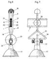
- FIGS. 6 and 7 show a further embodiment of a adapter unit 3 according to the invention can be seen. With those in it Embodiments shown are the same parts provided with the same reference numerals.
- contact elements 20 are also designed as flat cylindrical disks. These are designed as flat cylindrical disks Contact elements 20 are with the holding rods 8 over Spot welds 21 connected. The spot welds 21 are on the low-voltage track 1 opposite side of the contact elements 20.
- holding means 19 which act as a cap are executed that are parallel to the ends of both Sections 9 of the holding rods 8 can be pushed on.
- the cap has a in the illustrated embodiment part-spherical structure.
- the holding rods 8 have the Embodiment according to FIGS. 6 and 7 instead of the V-shaped one Section 10 on a section 18, the partial is rotated by 90 ° and is bow-shaped to the outside extends.
- the mounting block 22 in the in Fig. 6 and Fig. 7 illustrated embodiment has a groove in the middle in which a decorative disc 23 is inserted.
- This Decorative disc 23 can be made of an insulating material be so that through this decorative disc 23 at the same time Insulation between the two poles of the mounting block 22 is guaranteed.
Landscapes
- Engineering & Computer Science (AREA)
- General Engineering & Computer Science (AREA)
- Fastening Of Light Sources Or Lamp Holders (AREA)
- Non-Portable Lighting Devices Or Systems Thereof (AREA)
Applications Claiming Priority (2)
| Application Number | Priority Date | Filing Date | Title |
|---|---|---|---|
| DE19931757 | 1999-07-08 | ||
| DE1999131757 DE19931757B4 (de) | 1999-07-08 | 1999-07-08 | Niedervoltstromschienensystem für Leuchten |
Publications (2)
| Publication Number | Publication Date |
|---|---|
| EP1067331A2 true EP1067331A2 (fr) | 2001-01-10 |
| EP1067331A3 EP1067331A3 (fr) | 2004-11-03 |
Family
ID=7914033
Family Applications (1)
| Application Number | Title | Priority Date | Filing Date |
|---|---|---|---|
| EP00113206A Withdrawn EP1067331A3 (fr) | 1999-07-08 | 2000-06-21 | Système de rails en très basse tension pour éclairage et adaptateur pour un système de rails en très basse tension |
Country Status (2)
| Country | Link |
|---|---|
| EP (1) | EP1067331A3 (fr) |
| DE (1) | DE19931757B4 (fr) |
Citations (1)
| Publication number | Priority date | Publication date | Assignee | Title |
|---|---|---|---|---|
| DE4124066A1 (de) | 1991-07-19 | 1993-01-21 | Ind Und Design Licht Inh Domin | Elektrisches leuchtensystem |
Family Cites Families (10)
| Publication number | Priority date | Publication date | Assignee | Title |
|---|---|---|---|---|
| US4861273A (en) * | 1987-10-13 | 1989-08-29 | Thomas Industries, Inc. | Low-voltage miniature track lighting system |
| DE8809482U1 (de) * | 1988-07-25 | 1988-10-20 | Achtelik, Peter, 8034 Germering | Haltebügelvorrichtung für eine Lampe |
| DE8811846U1 (de) * | 1988-09-17 | 1988-10-27 | Bredin, Achim, 7425 Hohenstein | Stromband - Niedervoltleuchte |
| DE8814295U1 (de) * | 1988-11-15 | 1989-02-16 | Kurz, Josef, 8000 München | Elektrische Leuchte |
| DE4104481A1 (de) * | 1991-02-14 | 1992-08-20 | Czerny Heribert | Einrichtung zur gleichzeitigen schall- und lichteffekt-abstrahlung |
| US5340322A (en) * | 1993-04-22 | 1994-08-23 | Poulsen Peder Ulrik | Low voltage cable lighting system |
| DE9404914U1 (de) * | 1994-03-23 | 1994-08-04 | Bruck GmbH & Co KG, 44628 Herne | Niedervolt-Stromleitung |
| DE19510507C2 (de) * | 1995-03-23 | 1999-11-18 | Alulite Lichtsysteme Gmbh | Elektrisches Leuchtensystem |
| DE29816627U1 (de) * | 1998-09-17 | 1998-12-10 | Baranowski, Mike, 44805 Bochum | Niedervolt-Beleuchtungssystem |
| DE29820300U1 (de) * | 1998-11-16 | 1999-01-28 | Wiegelmann GmbH, 59823 Arnsberg | Niedervoltinstallationssystem |
-
1999
- 1999-07-08 DE DE1999131757 patent/DE19931757B4/de not_active Expired - Fee Related
-
2000
- 2000-06-21 EP EP00113206A patent/EP1067331A3/fr not_active Withdrawn
Patent Citations (1)
| Publication number | Priority date | Publication date | Assignee | Title |
|---|---|---|---|---|
| DE4124066A1 (de) | 1991-07-19 | 1993-01-21 | Ind Und Design Licht Inh Domin | Elektrisches leuchtensystem |
Also Published As
| Publication number | Publication date |
|---|---|
| EP1067331A3 (fr) | 2004-11-03 |
| DE19931757B4 (de) | 2008-07-10 |
| DE19931757A1 (de) | 2001-01-11 |
Similar Documents
| Publication | Publication Date | Title |
|---|---|---|
| EP0307396B1 (fr) | Appareil d'eclairage | |
| EP0281914B1 (fr) | Lampe réglable à basse-tension | |
| EP0291989B1 (fr) | Barre omnibus à basse tension | |
| DE69716701T2 (de) | Luminar | |
| EP0795216B1 (fr) | Dispositif d'alimentation en courant pour appareils basse tension | |
| EP1067331A2 (fr) | Système de rails en très basse tension pour éclairage et adaptateur pour un système de rails en très basse tension | |
| EP0874423B1 (fr) | Fixation pour barre de courant | |
| DE3817133C2 (fr) | ||
| DE8712088U1 (de) | Elektro-Kochplatte | |
| DE19624789C2 (de) | Dachzeichen für Kraftfahrzeuge, insbesondere Taxidachzeichen | |
| DE3800792A1 (de) | Durch einspannen zwischen boden und decke eines raumes aufstellbare leuchte | |
| DE19615525A1 (de) | Niedervoltstromschienensystem für Leuchten | |
| DE19750100C2 (de) | Verbindungsvorrichtung | |
| CH680479A5 (en) | Flexible current rail for LV load - has elongate flexible substrate supporting two parallel current conductors | |
| EP0346348B1 (fr) | Agencement conducteur de courant | |
| EP0649196B1 (fr) | Système d'installation à basse tension | |
| DE3834569A1 (de) | Niedervolt-beleuchtungsvorrichtung | |
| AT400373B (de) | Einstellbare lampenhalterung | |
| DE3700661A1 (de) | Beleuchtungseinrichtung | |
| DE803918C (de) | Fassung fuer elektrische Gluehlampen, insbesondere in Grubenhandlampen | |
| DE4334067A1 (de) | Niedervoltinstallationssystem | |
| DE2060475C3 (de) | Kabelanschluß eines explosionsgeschfitzten Gerätes | |
| EP0771999A2 (fr) | Système de rails en très basse tension pour éclairage | |
| DE3512712A1 (de) | Leuchte, insbesondere fuer ein kraftfahrzeug | |
| DE4410811A1 (de) | Leuchtelement |
Legal Events
| Date | Code | Title | Description |
|---|---|---|---|
| PUAI | Public reference made under article 153(3) epc to a published international application that has entered the european phase |
Free format text: ORIGINAL CODE: 0009012 |
|
| AK | Designated contracting states |
Kind code of ref document: A2 Designated state(s): AT BE CH CY DE DK ES FI FR GB GR IE IT LI LU MC NL PT SE |
|
| AX | Request for extension of the european patent |
Free format text: AL;LT;LV;MK;RO;SI |
|
| PUAL | Search report despatched |
Free format text: ORIGINAL CODE: 0009013 |
|
| AK | Designated contracting states |
Kind code of ref document: A3 Designated state(s): AT BE CH CY DE DK ES FI FR GB GR IE IT LI LU MC NL PT SE |
|
| AX | Request for extension of the european patent |
Extension state: AL LT LV MK RO SI |
|
| RIC1 | Information provided on ipc code assigned before grant |
Ipc: 7H 01R 25/14 B Ipc: 7F 21V 21/34 A |
|
| AKX | Designation fees paid | ||
| REG | Reference to a national code |
Ref country code: DE Ref legal event code: 8566 |
|
| STAA | Information on the status of an ep patent application or granted ep patent |
Free format text: STATUS: THE APPLICATION IS DEEMED TO BE WITHDRAWN |
|
| 18D | Application deemed to be withdrawn |
Effective date: 20050504 |