EP1067338A2 - Procédé et dispositif d'optimisation des émissions de NOx dans une turbine à gaz - Google Patents
Procédé et dispositif d'optimisation des émissions de NOx dans une turbine à gaz Download PDFInfo
- Publication number
- EP1067338A2 EP1067338A2 EP00305650A EP00305650A EP1067338A2 EP 1067338 A2 EP1067338 A2 EP 1067338A2 EP 00305650 A EP00305650 A EP 00305650A EP 00305650 A EP00305650 A EP 00305650A EP 1067338 A2 EP1067338 A2 EP 1067338A2
- Authority
- EP
- European Patent Office
- Prior art keywords
- gas turbine
- temperature adjustment
- fuel
- outer ring
- inner ring
- Prior art date
- Legal status (The legal status is an assumption and is not a legal conclusion. Google has not performed a legal analysis and makes no representation as to the accuracy of the status listed.)
- Granted
Links
Images


Classifications
-
- F—MECHANICAL ENGINEERING; LIGHTING; HEATING; WEAPONS; BLASTING
- F02—COMBUSTION ENGINES; HOT-GAS OR COMBUSTION-PRODUCT ENGINE PLANTS
- F02C—GAS-TURBINE PLANTS; AIR INTAKES FOR JET-PROPULSION PLANTS; CONTROLLING FUEL SUPPLY IN AIR-BREATHING JET-PROPULSION PLANTS
- F02C7/00—Features, components parts, details or accessories, not provided for in, or of interest apart form groups F02C1/00 - F02C6/00; Air intakes for jet-propulsion plants
- F02C7/22—Fuel supply systems
-
- F—MECHANICAL ENGINEERING; LIGHTING; HEATING; WEAPONS; BLASTING
- F02—COMBUSTION ENGINES; HOT-GAS OR COMBUSTION-PRODUCT ENGINE PLANTS
- F02C—GAS-TURBINE PLANTS; AIR INTAKES FOR JET-PROPULSION PLANTS; CONTROLLING FUEL SUPPLY IN AIR-BREATHING JET-PROPULSION PLANTS
- F02C9/00—Controlling gas-turbine plants; Controlling fuel supply in air- breathing jet-propulsion plants
- F02C9/26—Control of fuel supply
- F02C9/28—Regulating systems responsive to plant or ambient parameters, e.g. temperature, pressure, rotor speed
-
- F—MECHANICAL ENGINEERING; LIGHTING; HEATING; WEAPONS; BLASTING
- F05—INDEXING SCHEMES RELATING TO ENGINES OR PUMPS IN VARIOUS SUBCLASSES OF CLASSES F01-F04
- F05D—INDEXING SCHEME FOR ASPECTS RELATING TO NON-POSITIVE-DISPLACEMENT MACHINES OR ENGINES, GAS-TURBINES OR JET-PROPULSION PLANTS
- F05D2270/00—Control
- F05D2270/01—Purpose of the control system
- F05D2270/08—Purpose of the control system to produce clean exhaust gases
- F05D2270/082—Purpose of the control system to produce clean exhaust gases with as little NOx as possible
-
- F—MECHANICAL ENGINEERING; LIGHTING; HEATING; WEAPONS; BLASTING
- F05—INDEXING SCHEMES RELATING TO ENGINES OR PUMPS IN VARIOUS SUBCLASSES OF CLASSES F01-F04
- F05D—INDEXING SCHEME FOR ASPECTS RELATING TO NON-POSITIVE-DISPLACEMENT MACHINES OR ENGINES, GAS-TURBINES OR JET-PROPULSION PLANTS
- F05D2270/00—Control
- F05D2270/30—Control parameters, e.g. input parameters
- F05D2270/303—Temperature
Definitions
- This invention relates generally to fuel-air optimization in annular gas turbine combustors and more particularly concerns a system for continual on-line trimming of the fuel flow rate to rings of a annular combustor to optimize NO x emissions.
- FIG 1 shows a gas turbine combustor from a Dry Low Emissions (DLE) Industrial Engine, such as the GE LM6000TM, which includes a compressor 2, a combustor 3 and a turbine 4. Fuel is mixed with compressed air from the compressor 2 and burned in the combustor 3. The resulting flow of combustion products out of the combustor 3 drives the turbine 4, which in turn drives a load (not shown) as well as the compressor 2. The exhaust from the turbine 4 is eventually released to the atmosphere.
- combustor commonly used today is the so-called annular combustor.
- One exemplary embodiment of the annular combustor comprises a plurality of separate rings, wherein each ring is connected to the compressor 2 and the fuel supply provides combustion products to drive turbine 4. This combustor is fully described in US Patent number 5,323,604.
- Figure 1 further shows one embodiment of a DLE type annular combustor 3 having three rings 5,7, and 9.
- the rings define a combustion chamber (not shown) to which a fuel-air mixture from an inner ring premixer 12, a pilot ring premixer 16, and an outer ring premixer 18 is injected.
- Compressed air enters each of the premixers 12, 16, and 18 via an air line 13 and fuel enters via a fuel line 14.
- a main valve 15, also referred to as a pilot value is disposed in the fuel line 14 to throttle the flow of fuel into each of outer ring premixer 12 and inner ring premixer 18.
- the fuel and air may be directly injected into the combustion chamber without premixing.
- a fuel control method for controlling the ratio of ring temperature adjustment in rings of a combustor in a gas turbine comprising the steps of: defining an operational boundary of inner ring temperature adjustment versus an outer ring temperature adjustment; calculating a global minimum of operation of the inner ring fuel temperature adjustment versus the outer ring fuel temperature adjustment within a safety margin of the operational boundary, wherein the NO x emission level of the gas turbine is reduced; and regulating the ring temperatures to maintain the inner ring temperature adjustment and the outer ring temperature adjustment near the global minimum point of operation, while maintaining normal operation of the gas turbine.
- the operational boundary is identified when the combustor dynamic pressure is greater than a specified limit.
- the combustor dynamic pressure may have a specified limit in a range from about zero to about 15,000 Pascals.
- the gas turbine may be verified to be in an ABC mode, an AB mode and/or a BC mode.
- the NO x emissions may be measured at a predetermined number of operational points, e.g. at least six, within the operational boundary.
- the method may further comprise the step of performing a polynomial curve-fit on the operational points and may comprise the step of calculating a global minimum operation point.
- the method may further comprise the step of setting the inner ring temperature adjustment and the outer ring temperature adjustment so as to cause the gas turbine to operate within a safety margin of the global minimum.
- the step of calculating the global minimum operating point may further comprise the step of determining whether a preferred boundary has been crossed.
- the method may further comprise the step of setting the inner ring temperature adjustment and the outer ring temperature adjustment so as to cause the gas turbine to revert to an operating point one safety margin unit away from the global minimum if the preferred boundary has been crossed.
- the method may further comprise the step of determining whether the preferred boundary has been crossed.
- the method may further comprise the step of setting the inner ring temperature adjustment and the outer ring temperature adjustment so as to cause the gas turbine to revert to an operating point one safety margin unit away from the global minimum if the preferred boundary has been crossed.
- the method may further comprise the step of setting the inner ring temperature adjustment and the outer ring temperature adjustment so as to cause the gas turbine to revert to the global minimum operating point if the preferred boundary was not crossed.
- the method may further comprise the step of setting the inner ring temperature adjustment and the outer ring temperature adjustment so as to cause the gas turbine to revert to an operating point being one safety margin away from the global minimum if the preferred boundary has been crossed.
- the NO x emissions may be measured at a predetermined number of operational points, e.g. at least three, within the operational boundary.
- the method may further comprise the step of performing a polynomial curve-fit on the operational points.
- the method may further comprise the step of calculating a local minimum operation point based on a first derivative of the curve-fit.
- the method may further comprise the step of setting the inner ring temperature adjustment and the outer ring temperature adjustment so as to cause the gas turbine to operate at the local minimum.
- the method may further comprise the step of step of setting the inner ring temperature adjustment and the outer ring temperature adjustment so as to cause the gas turbine to operate along a local minimum line until reaching the preferred boundary.
- the method may further comprise the step of setting the inner ring temperature adjustment and the outer ring temperature adjustment so as to cause the gas turbine to operate within a safety margin of the preferred boundary.
- an apparatus for controlling the fuel flow to a plurality of rings in an annular combustor of a gas turbine comprising: a turbine controller, wherein the turbine controller is adapted to generate a nominal operating temperature for each of the plurality of rings of the combustor; a NO x regulator coupled to the turbine controller, wherein the NO x regulator is adapted to reduce NO x emission levels in the gas turbine by adjusting at least one ring temperature of the annular combustor; an inner ring fuel adjuster coupled to the NO x regulator, wherein the inner ring fuel adjuster is adapted to adjust the inner ring temperature of the combustor within a specified limit; and an outer ring fuel adjuster coupled to the NO x regulator, wherein the outer ring fuel adjuster is adapted to adjust the outer ring temperature of the combustor within a specified limit.
- the NO x regulator may further comprise a digital signal processor and may comprise:- a microprocessor; an analog to digital converter coupled to the microprocessor at least one digital to analog converter coupled to the microprocessor; and a multiplexer coupled to the analog to digital converter.
- the specified limit may be in a range from about negative 65 degrees Celsius to about positive 65 degrees Celsius about a nominal operating temperature.
- the NO x regulator may comprises a first algorithm, wherein the first algorithm is adapted to define an operational boundary of an inner ring temperature adjustment versus an outer ring temperature adjustment; calculate a global minimum of operation of the inner ring fuel temperature adjustment versus the outer ring fuel temperature adjustment within a safety margin of the operational boundary, wherein the NO x emission level of the gas turbine is reduced; and regulate the ring temperatures to maintain the inner ring temperature adjustment and the outer ring temperature adjustment near the global minimum point of operation.
- the NO x regulator may comprise a second algorithm, wherein the second algorithm is adapted to verity that the gas turbine is in an ABC mode of operation; acquire NO x measurements during normal operation of the gas turbine, which correspond to at least six boundary points; perform a polynomial curve-fit on the at least six boundary points to generate a NO x equation that corresponds with each of the ring temperatures; calculate the global minimum point of operation wherein the gas turbine generates reduced NO x emission levels; and regulate the gas turbine to operate at near the calculated global minimum operating point, while maintaining normal operation of the gas turbine.
- a NO x regulator for reducing NO x emissions of a gas turbine
- the NO x regulator comprises an algorithm, wherein the algorithm is adapted to define an operational boundary of an inner ring temperature adjustment versus an outer ring temperature adjustment; calculate a global minimum of operation of the inner ring fuel temperature adjustment versus the outer ring fuel temperature adjustment within a safety margin of the operational boundary, wherein the NO x emission level of the gas turbine is reduced; and regulate the ring temperatures to maintain the inner ring temperature adjustment and the outer ring temperature adjustment near the global minimum point of operation, while maintaining normal operation of the gas turbine.
- a NO x regulator comprising an algorithm, wherein the algorithm is adapted to verity that the gas turbine is in an ABC mode of operation; acquire NO x measurements during normal operation of the gas turbine, which correspond to at least six boundary points; perform a polynomial curve-fit on the at least six boundary points to generate a NO x equation that corresponds with each of the ring temperatures; calculate the global minimum point of operation wherein the gas turbine generates reduced NO x emission levels; and regulate the gas turbine to operate at near the calculated global minimum operating point, while maintaining normal operation of the gas turbine.
- the present invention comprises a fuel control system for controlling the ratio of ring temperature adjustment in at least one ring of an annular combustor in a gas turbine.
- the fuel control system consists of a computer to perform the steps of; 1) defining an operational boundary of inner ring temperature adjustment versus an outer ring temperature adjustment that defines a safe operating region for the gas turbine; 2) calculating a operating point of the inner ring temperature adjustments versus the outer ring temperature adjustment within a safety margin of the operational boundary, wherein NO x emission levels of the gas turbine is substantially minimized; and 3) regulating each ring temperature adjustment to maintain a near global minimum point of operation while maintaining normal operating parameters.
- the present invention addresses the issue of reducing emissions of harmful NO x gases produced by a gas turbine.
- NO x emissions are very sensitive to combustor temperature in a gas turbine and the amount of NO x produced is an exponential function of temperature.
- NO x refers to various oxides of Nitrogen.
- the present invention is also adapted to operate the gas turbine to minimize high levels of acoustic noise, to eliminate turbine blow-out based on unacceptably lean fuel, and to reduce high levels of Carbon Monoxide (CO).
- CO Carbon Monoxide
- a controller 20 is coupled to an inner ring fuel valve 22, a pilot ring fuel valve 14, and an outer ring fuel valve 24 to regulate the flow of fuel to respective premixers 18, 16, and 12 via an inner ring fuel signal 36, an pilot ring fuel signal 40, and an outer ring fuel signal 24.
- a plurality of control signals are coupled from the turbine engine to controller 20, including, for example, dynamic pressure P x (26), (the dynamic peak-to-peak dynamic pressure of combustor 3), NO x (34), inner ring temperature (30), outer ring temperature (28), and fuel valve position status (32).
- control signals are only a representative subset of the control signals that may be used by controller 20 to control the gas turbine, It is also understood that signals P x dynamic pressure 26, outer ring temperature 28, inner ring temperature 30, and NO x emission level 34, may be calculated in the controller from other measured signals, and not necessarily measured directly by sensors.
- Controller 20 which comprises a turbine controller 50 and a NO x regulator 56.
- Controller 20 further comprises an inner ring fuel adjuster 52, outer ring fuel adjuster 54, which inner ring adjuster 52 and outer ring adjuster 54 are respectively coupled to an inner ring fuel driver 36 and an outer ring fuel driver 38.
- Main fuel driver is coupled to turbine controller 50.
- NO x regulator 56 is coupled to inner ring fuel adjuster 52 and outer ring fuel adjuster 54. Because of the connection arrangement, NO x regulator 56 only has the ability to adjust the fuel flowing to inner fuel valve 22 and outer fuel valve 24.
- Inner fuel driver 36 generates inner ring fuel signal 36
- outer ring fuel driver 62 generates outer ring fuel signal 38. Pilot ring fuel signal 36 is derived from the difference between the total fuel flow and the sum of inner fuel flow and outer fuel flow.
- Main fuel valve 14 acts to regulate the total fuel flow to the combustor.
- Inner ring fuel valve 22 and outer ring fuel valve 24 is coupled to inner ring 5 and outer ring 9. Further, the regulation of fuel flow by inner ring fuel value 22 and outer ring fuel valve 24 is limited by turbine controller 50. Because of the limitation imposed on the fuel control system by the above description, design constraints of the gas turbine which define the dynamic operating range of combustor 3 is also controlled by turbine controller 50. In the event that NO x regulator 56 fails, turbine controller 50 continues to control the operation of the gas turbine in a fail safe mode. NO x regulator 56 is designed to make adjustments only to the fuel flow of inner ring 5 and outer ring 9.
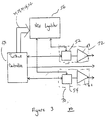
- NO x regulator 56 is a stand alone control device rather than being integrated into controller 20, as illustrated in Figure 3.
- Inner ring fuel adjuster 52 and inner ring fuel valve driver 58 may also be integrated into a single adjuster and inner ring valve driver 72.
- outer ring fuel adjuster 54 and the associated driver 62 may be integrated into outer ring adjuster and driver 70.
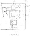
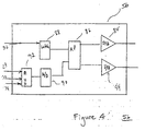
- NO x regulator 56 comprises a micro-processor 86, wherein micro-processor 86 is coupled to at least one digital-to-analog converter 84, a digital latch 88 to read digital signal 32, and an analog-to-digital converter 90, as illustrated in Figure 4.
- Analog-to-digital converter 90 may also be coupled to an analog multiplexer 92 so as to read analog signals 28, 30, and 34.
- NO x regulator 56 may alternatively comprise a digital signal processor having the above described digital and analog functions built in.
- NO x regulator 56 operates fuel valves 22 and 24 so as to control the fuel flow to inner ring premixer 18 and outer ring premixer 12. By regulating fuel flow in this manner the amount of fuel from the outer ring 9, pilot ring 7, and inner ring 5 of combustor 3 is regulated. The fuel flow determines fuel-air-ratio in each ring of combustor 3, which in turn determines the temperature in each ring. Because the temperatures in inner ring 5, pilot ring 7, and outer ring 9 determines the amount of NO x produced by combustor 3, NO x regulator 56 acts to control NO x emissions in combustor 3, as is further described below.
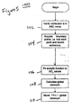
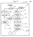
- Figure 5 illustrates a process flow diagram 100 for determining the near optimum operating point to minimize NO x emissions in a gas turbine.
- this data is provided to NO x regulator 56 from turbine controller 50 via fuel valve status line 32 ( Figure 2).
- the present invention operates in the mode where inner ring 5, pilot ring 7, and outer ring 9 are concurrently being controlled by turbine controller 50, identified as the ABC mode.
- modes AB and BC are within the scope of the present invention, such as, modes AB and BC, wherein mode AB is defined as the mode when inner ring valve 22 is shut off and mode BC is defined as the mode when outer ring valve 24 is shut off.
- a specified number of gas turbine operating points are identified along an operation boundary 156 defined by combustion chamber temperatures at inner ring 5 and outer ring 9.
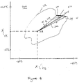
- One exemplary illustration of these operating points are shown, for example, by operating points 160, 162, 164, 166, 168, and 170, illustrated in Figure 6.
- Each of operating points 160, 162, 164, 166, 168, 170 was selected to be disposed along three planes which intersect at nominal operating point 158. It is understood that any method for selecting the operating points may be utilized.
- the goal is to select a specified number of operating points disposed along operating boundary 156.
- NO x levels are measured during normal operation of the gas turbine.
- the point selection and NO x measurement process step is illustrated by step 104 of Figure 5.
- a boundary point 156 is defined as an operating point of the gas turbine engine within a defined preferred operating region 154.
- the preferred operating region is defined as the region where a number of conditions are generally met, such as, when the dynamic operating range of combustor 3 is satisfied, when gas turbine acoustic noise is low, when the gas turbine is not in a blow-out range, when CO is low, and when NO x is below a high upper limit. NO x typically comprise about 25 parts per million volume exhaust gas. These conditions are generally met when dynamic pressure P x is within a specified pressure range during operation, typically, between about zero and about 15,000 Pascals. The more specific dynamic pressure range is gas turbine specific, and is typically provided by the gas turbine manufacturer.
- the non-preferred operating region 156 which is any area not in the preferred operating region, is to be avoided.
- Figure 6 further provides a graphical illustration of the fuel temperature adjustment range of a typical annular combustor of a gas turbine.
- the range of inner ring temperature adjustment is from about negative 65 degrees Celsius to about positive 65 degrees Celsius above and below a nominal operating ring temperature 158 that is set by turbine control 50.
- This inner ring temperature adjustment range is represented by the horizontal axis of Figure 6.
- the range of outer ring temperature adjustment is from about negative 65 degrees Celsius to about positive 65 degrees Celsius above and below nominal operating ring temperature 158.
- This outer ring temperature adjustment range is represented by the vertical axis of Figure 6.
- This polynomial function is at least a second-order polynomial function having the form identified in equation 1.
- NO x ⁇ 0 + ⁇ 1 x + ⁇ 2 y + ⁇ 3 xy + ⁇ 4 x 2 + ⁇ 5 y 2
- the variable "x" corresponds with the inner ring temperature adjustment 172 and the variable "y" corresponds with the outer ring temperature adjustment 174, illustrated in Figure 6.
- the "x" and "y” value where NO x is minimized is calculated by taking a partial derivative of equation 1 with respect to "x" and a partial derivative with respect to "y", represented by step 108 of Figure 5.
- the resulting point is defined as the global minimum157 and is depicted in Figure 6. It is noted that the global minimum 157 may be in the non-preferred region.
- the gas turbine inner and outer ring temperature adjustments are incremented so that the gas turbine is operating either at the global minimum 157 or near the global minimum 157 within the preferred operating region, step 110 of Figure 5.
- NO x emission levels are reduced in a range from about 10 percent to about 20 percent from levels occurring when the present invention in not utilized.
- near global optimum operating point is therefore defined as the operating point in which the NO x emission levels are reduced in a range from about 10 % to about 20 % from nominal operating emission levels.
- the process for operation of the gas turbine at or near the global minimum is further described next.
- Safety margin "r” is the margin as measured by inner ring temperature adjustment and outer ring temperature adjustment, in which the gas turbine operates within the preferred region.
- Safety margin "r” is typically about 15 degrees Celsius. It is understood that the safety margin is dependent upon the accuracy of the control system and the response of the gas turbine and may change as appropriate for any given gas turbine system.
- the inner ring temperature adjustment and outer ring temperature adjustment are incremented so that the gas turbine operation is adjusted starting at the nominal operating point 158 ( Figure 6), along a global margin line 159 extending from nominal operating point 158 to global minimum 157, as identified by step 112 of Figure 7.
- the operating boundary 156 has been crossed, in which case the gas turbine would be operating in the non-preferred region 152, as identified by step 118 of Figure 7.
- b 0 , b 1 , and b 2 are coefficients that are calculated using a least squares regression or curve fit function from NO x values 210,212, and 214.
- Angle ⁇ is any one of two specified angles ( ⁇ 1 and ⁇ 2 ) defined by the set operating points 158, 210, and 212 ( ⁇ 1 ), and 158, 210, and 214 ( ⁇ 2 ), as illustrated in Figure 8. The purpose of this calculation is to determine a local minimum point of operation 204 along the arc defined by operating points 210, 212, and 214 near the operating boundary 156. The derivative with respect to the ⁇ angle is determined and solved for NO x equal zero.
- a local minimum line 202 is next determined, wherein local minimum line 202 is defined as the line between nominal operating point 158 and the local minimum point 204.
- the gas turbine is incremented from nominal operating point 158 along local minimum line 202 until the operating point 222, which is a safety margin "r" away from the local minimum point 204.
- Operating point 171 is the near global operating point of the gas turbine. The near global operating point is defined as the operating point at which NO x emission levels are reduced in a range from about 10 percent to about 20 percent from nominal NO x emission levels when the gas turbine is operating and the present invention is not utilized.
- the methods described herein may be used to optimize the output of any chemical reactor which has several parameters that can be controlled and several output variables.
- the method described herein which reduce NO x emissions by optimizing ring flame temperatures can also be used simultaneously with Carbon Monoxide reducing algorithms, such as those described in US Patents 4,910,957 and 4,928,481.
Landscapes
- Engineering & Computer Science (AREA)
- Chemical & Material Sciences (AREA)
- Combustion & Propulsion (AREA)
- Mechanical Engineering (AREA)
- General Engineering & Computer Science (AREA)
- Engine Equipment That Uses Special Cycles (AREA)
Applications Claiming Priority (2)
| Application Number | Priority Date | Filing Date | Title |
|---|---|---|---|
| US09/347,719 US6195607B1 (en) | 1999-07-06 | 1999-07-06 | Method and apparatus for optimizing NOx emissions in a gas turbine |
| US347719 | 1999-07-06 |
Publications (3)
| Publication Number | Publication Date |
|---|---|
| EP1067338A2 true EP1067338A2 (fr) | 2001-01-10 |
| EP1067338A3 EP1067338A3 (fr) | 2002-12-11 |
| EP1067338B1 EP1067338B1 (fr) | 2008-04-16 |
Family
ID=23364955
Family Applications (1)
| Application Number | Title | Priority Date | Filing Date |
|---|---|---|---|
| EP00305650A Expired - Lifetime EP1067338B1 (fr) | 1999-07-06 | 2000-07-05 | Procédé et dispositif d'optimisation des émissions de NOx dans une turbine à gaz |
Country Status (4)
| Country | Link |
|---|---|
| US (1) | US6195607B1 (fr) |
| EP (1) | EP1067338B1 (fr) |
| JP (1) | JP2001041055A (fr) |
| DE (1) | DE60038593T2 (fr) |
Cited By (10)
| Publication number | Priority date | Publication date | Assignee | Title |
|---|---|---|---|---|
| WO2002061337A1 (fr) * | 2001-01-30 | 2002-08-08 | Alstom (Switzerland) Ltd | Unite de bruleurs et son procede de fonctionnement |
| EP1288467A1 (fr) * | 2001-08-24 | 2003-03-05 | Mitsubishi Heavy Industries, Ltd. | Système de chambre de combustion de turbine à gaz |
| EP1387062A3 (fr) * | 2002-08-02 | 2004-12-22 | General Electric Company | Procédé/système pour le mappage de chambre de combustion dans une turbine à gaz |
| US7137809B2 (en) | 2001-01-30 | 2006-11-21 | Alstom Technology Ltd. | Method for the production of a burner unit |
| EP2071156A1 (fr) * | 2007-12-10 | 2009-06-17 | ALSTOM Technology Ltd | Système de distribution de carburant d'une turbine à gaz avec ensemble brûleur à plusieurs étages |
| EP2249007A3 (fr) * | 2009-05-08 | 2013-07-24 | Gas Turbine Efficiency Sweden AB | Accordage automatique des systèmes de combustion d'une turbine à gaz |
| CN103410618A (zh) * | 2013-08-16 | 2013-11-27 | 上海明华电力技术工程有限公司 | 燃气轮机干式低NOx燃烧调整方法 |
| US9267443B2 (en) | 2009-05-08 | 2016-02-23 | Gas Turbine Efficiency Sweden Ab | Automated tuning of gas turbine combustion systems |
| US9354618B2 (en) | 2009-05-08 | 2016-05-31 | Gas Turbine Efficiency Sweden Ab | Automated tuning of multiple fuel gas turbine combustion systems |
| US9671797B2 (en) | 2009-05-08 | 2017-06-06 | Gas Turbine Efficiency Sweden Ab | Optimization of gas turbine combustion systems low load performance on simple cycle and heat recovery steam generator applications |
Families Citing this family (24)
| Publication number | Priority date | Publication date | Assignee | Title |
|---|---|---|---|---|
| US6405523B1 (en) | 2000-09-29 | 2002-06-18 | General Electric Company | Method and apparatus for decreasing combustor emissions |
| US6484489B1 (en) | 2001-05-31 | 2002-11-26 | General Electric Company | Method and apparatus for mixing fuel to decrease combustor emissions |
| US6418726B1 (en) | 2001-05-31 | 2002-07-16 | General Electric Company | Method and apparatus for controlling combustor emissions |
| US6722135B2 (en) * | 2002-01-29 | 2004-04-20 | General Electric Company | Performance enhanced control of DLN gas turbines |
| US6865889B2 (en) * | 2002-02-01 | 2005-03-15 | General Electric Company | Method and apparatus to decrease combustor emissions |
| US6694742B2 (en) | 2002-06-26 | 2004-02-24 | General Electric Company | Gas turbine system operation based on estimated stress |
| US20040103068A1 (en) * | 2002-11-22 | 2004-05-27 | Eker Sukru Alper | Process for optimally operating an energy producing unit and an energy producing unit |
| US6871501B2 (en) * | 2002-12-03 | 2005-03-29 | General Electric Company | Method and apparatus to decrease gas turbine engine combustor emissions |
| US6862889B2 (en) | 2002-12-03 | 2005-03-08 | General Electric Company | Method and apparatus to decrease combustor emissions |
| US6837056B2 (en) * | 2002-12-19 | 2005-01-04 | General Electric Company | Turbine inlet air-cooling system and method |
| US7065955B2 (en) * | 2003-06-18 | 2006-06-27 | General Electric Company | Methods and apparatus for injecting cleaning fluids into combustors |
| US7059135B2 (en) * | 2004-08-30 | 2006-06-13 | General Electric Company | Method to decrease combustor emissions |
| US7185495B2 (en) | 2004-09-07 | 2007-03-06 | General Electric Company | System and method for improving thermal efficiency of dry low emissions combustor assemblies |
| US7487642B2 (en) * | 2005-11-01 | 2009-02-10 | General Electric Comapny | Methods and apparatus for operating gas turbine engines |
| US20070189948A1 (en) * | 2006-02-14 | 2007-08-16 | Rocha Teresa G | Catalyst system and method |
| US7840332B2 (en) * | 2007-02-28 | 2010-11-23 | General Electric Company | Systems and methods for steam turbine remote monitoring, diagnosis and benchmarking |
| US7950215B2 (en) * | 2007-11-20 | 2011-05-31 | Siemens Energy, Inc. | Sequential combustion firing system for a fuel system of a gas turbine engine |
| US9890714B2 (en) * | 2009-05-26 | 2018-02-13 | Ansaldo Energia Ip Uk Limited | Automated extended turndown of a gas turbine engine combined with incremental tuning to maintain emissions and dynamics |
| US8365534B2 (en) | 2011-03-15 | 2013-02-05 | General Electric Company | Gas turbine combustor having a fuel nozzle for flame anchoring |
| US8955329B2 (en) | 2011-10-21 | 2015-02-17 | General Electric Company | Diffusion nozzles for low-oxygen fuel nozzle assembly and method |
| EP2738373A1 (fr) * | 2012-12-03 | 2014-06-04 | Siemens Aktiengesellschaft | Procédé d'alimentation en carburant et turbine à gaz et agencement |
| DE102013205356B4 (de) * | 2013-03-26 | 2016-07-07 | Siemens Aktiengesellschaft | Verfahren zur rechnergestützten Steuerung und/oder Regelung eines technischen Systems |
| WO2016123613A1 (fr) * | 2015-01-30 | 2016-08-04 | General Electric Technology Gmbh | Marge de réglage étendue automatique d'un moteur à turbine à gaz combinée avec un réglage incrémentiel pour maintenir les émissions et la dynamique |
| US12441295B2 (en) * | 2023-03-30 | 2025-10-14 | Ford Global Technologies, Llc | System and methods for in-use NOx robustness emission control |
Citations (3)
| Publication number | Priority date | Publication date | Assignee | Title |
|---|---|---|---|---|
| US4910957A (en) | 1988-07-13 | 1990-03-27 | Prutech Ii | Staged lean premix low nox hot wall gas turbine combustor with improved turndown capability |
| US4928481A (en) | 1988-07-13 | 1990-05-29 | Prutech Ii | Staged low NOx premix gas turbine combustor |
| US5323604A (en) | 1992-11-16 | 1994-06-28 | General Electric Company | Triple annular combustor for gas turbine engine |
Family Cites Families (13)
| Publication number | Priority date | Publication date | Assignee | Title |
|---|---|---|---|---|
| US4700542A (en) * | 1984-09-21 | 1987-10-20 | Wang Lin Shu | Internal combustion engines and methods of operation |
| US5487266A (en) * | 1992-05-05 | 1996-01-30 | General Electric Company | Combustion control for producing low NOx emissions through use of flame spectroscopy |
| US5309709A (en) * | 1992-06-25 | 1994-05-10 | Solar Turbines Incorporated | Low emission combustion system for a gas turbine engine |
| JP3278923B2 (ja) * | 1992-09-17 | 2002-04-30 | 株式会社日立製作所 | ガスタービン発電装置、脱硝装置の制御方法及び脱硝装置の制御装置 |
| US5365732A (en) | 1993-04-19 | 1994-11-22 | General Electric Company | Retrofittable trim system for fuel-air optimization in cannular gas turbine combustors |
| JPH08246903A (ja) * | 1995-03-07 | 1996-09-24 | Hitachi Ltd | ガスタービン発電装置およびその制御方法 |
| US5761895A (en) | 1995-08-28 | 1998-06-09 | General Electric Company | Transient load controller for gas turbine power generator |
| JPH09166326A (ja) * | 1995-12-15 | 1997-06-24 | Hitachi Ltd | ガスタービン燃焼器 |
| JP3670382B2 (ja) * | 1996-03-18 | 2005-07-13 | 株式会社東芝 | ガスタービン燃焼監視装置 |
| US5850732A (en) | 1997-05-13 | 1998-12-22 | Capstone Turbine Corporation | Low emissions combustion system for a gas turbine engine |
| JPH10317991A (ja) * | 1997-05-15 | 1998-12-02 | Hitachi Ltd | ガスタービン |
| JP3771677B2 (ja) * | 1997-07-07 | 2006-04-26 | 三菱重工業株式会社 | パイロット比自動調整装置 |
| JP3703615B2 (ja) * | 1997-12-12 | 2005-10-05 | 株式会社東芝 | ガスタービン装置 |
-
1999
- 1999-07-06 US US09/347,719 patent/US6195607B1/en not_active Expired - Fee Related
-
2000
- 2000-07-04 JP JP2000201698A patent/JP2001041055A/ja active Pending
- 2000-07-05 EP EP00305650A patent/EP1067338B1/fr not_active Expired - Lifetime
- 2000-07-05 DE DE60038593T patent/DE60038593T2/de not_active Expired - Lifetime
Patent Citations (3)
| Publication number | Priority date | Publication date | Assignee | Title |
|---|---|---|---|---|
| US4910957A (en) | 1988-07-13 | 1990-03-27 | Prutech Ii | Staged lean premix low nox hot wall gas turbine combustor with improved turndown capability |
| US4928481A (en) | 1988-07-13 | 1990-05-29 | Prutech Ii | Staged low NOx premix gas turbine combustor |
| US5323604A (en) | 1992-11-16 | 1994-06-28 | General Electric Company | Triple annular combustor for gas turbine engine |
Cited By (20)
| Publication number | Priority date | Publication date | Assignee | Title |
|---|---|---|---|---|
| WO2002061337A1 (fr) * | 2001-01-30 | 2002-08-08 | Alstom (Switzerland) Ltd | Unite de bruleurs et son procede de fonctionnement |
| US7137809B2 (en) | 2001-01-30 | 2006-11-21 | Alstom Technology Ltd. | Method for the production of a burner unit |
| US7198483B2 (en) | 2001-01-30 | 2007-04-03 | Alstom Technology Ltd. | Burner unit and method for operation thereof |
| EP1288467A1 (fr) * | 2001-08-24 | 2003-03-05 | Mitsubishi Heavy Industries, Ltd. | Système de chambre de combustion de turbine à gaz |
| US6880325B2 (en) | 2001-08-24 | 2005-04-19 | Mitsubishi Heavy Industries, Ltd. | Gas turbine combustor apparatus |
| EP1387062A3 (fr) * | 2002-08-02 | 2004-12-22 | General Electric Company | Procédé/système pour le mappage de chambre de combustion dans une turbine à gaz |
| US7302334B2 (en) | 2002-08-02 | 2007-11-27 | General Electric Company | Automatic mapping logic for a combustor in a gas turbine engine |
| US8776524B2 (en) | 2007-12-10 | 2014-07-15 | Alstom Technology Ltd. | Fuel distribution system for a gas turbine with multistage burner arrangement |
| EP2071156A1 (fr) * | 2007-12-10 | 2009-06-17 | ALSTOM Technology Ltd | Système de distribution de carburant d'une turbine à gaz avec ensemble brûleur à plusieurs étages |
| EP2249007A3 (fr) * | 2009-05-08 | 2013-07-24 | Gas Turbine Efficiency Sweden AB | Accordage automatique des systèmes de combustion d'une turbine à gaz |
| US9267443B2 (en) | 2009-05-08 | 2016-02-23 | Gas Turbine Efficiency Sweden Ab | Automated tuning of gas turbine combustion systems |
| US9328670B2 (en) | 2009-05-08 | 2016-05-03 | Gas Turbine Efficiency Sweden Ab | Automated tuning of gas turbine combustion systems |
| US9354618B2 (en) | 2009-05-08 | 2016-05-31 | Gas Turbine Efficiency Sweden Ab | Automated tuning of multiple fuel gas turbine combustion systems |
| US9671797B2 (en) | 2009-05-08 | 2017-06-06 | Gas Turbine Efficiency Sweden Ab | Optimization of gas turbine combustion systems low load performance on simple cycle and heat recovery steam generator applications |
| US10260428B2 (en) | 2009-05-08 | 2019-04-16 | Gas Turbine Efficiency Sweden Ab | Automated tuning of gas turbine combustion systems |
| US10509372B2 (en) | 2009-05-08 | 2019-12-17 | Gas Turbine Efficiency Sweden Ab | Automated tuning of multiple fuel gas turbine combustion systems |
| US11028783B2 (en) | 2009-05-08 | 2021-06-08 | Gas Turbine Efficiency Sweden Ab | Automated tuning of gas turbine combustion systems |
| US11199818B2 (en) | 2009-05-08 | 2021-12-14 | Gas Turbine Efficiency Sweden Ab | Automated tuning of multiple fuel gas turbine combustion systems |
| CN103410618A (zh) * | 2013-08-16 | 2013-11-27 | 上海明华电力技术工程有限公司 | 燃气轮机干式低NOx燃烧调整方法 |
| CN103410618B (zh) * | 2013-08-16 | 2015-09-02 | 上海明华电力技术工程有限公司 | 燃气轮机干式低NOx燃烧调整方法 |
Also Published As
| Publication number | Publication date |
|---|---|
| DE60038593T2 (de) | 2009-06-04 |
| EP1067338A3 (fr) | 2002-12-11 |
| JP2001041055A (ja) | 2001-02-13 |
| DE60038593D1 (de) | 2008-05-29 |
| US6195607B1 (en) | 2001-02-27 |
| EP1067338B1 (fr) | 2008-04-16 |
Similar Documents
| Publication | Publication Date | Title |
|---|---|---|
| US6195607B1 (en) | Method and apparatus for optimizing NOx emissions in a gas turbine | |
| EP1387062B1 (fr) | Procédé/système pour le mappage de chambre de combustion dans une turbine à gaz | |
| US6973791B2 (en) | Method and apparatus for reduction of combustor dynamic pressure during operation of gas turbine engines | |
| RU2540210C2 (ru) | Способ управления режимом работы газовой турбины на основе температуры выхлопного газа и газовая турбина | |
| US6796129B2 (en) | Design and control strategy for catalytic combustion system with a wide operating range | |
| US6877307B2 (en) | Automatic combustion control for a gas turbine | |
| JP5014432B2 (ja) | ガスタービンの燃焼プロセスを制御するシステム | |
| RU2539930C2 (ru) | Способ управления режимом работы газовой турбины на основе температуры выхлопного газа и газовая турбина | |
| US5551227A (en) | System and method of detecting partial flame out in a gas turbine engine combustor | |
| US11434825B2 (en) | Method and device to control a fuel split in a combustion device | |
| CN109790981B (zh) | 使用引燃空气控制燃烧系统的操作点的技术 | |
| JP3771677B2 (ja) | パイロット比自動調整装置 | |
| Corbett | Sensor requirements to control the industrial RB 211 dry low emission gas turbine | |
| JP2010248966A (ja) | ガスタービン燃焼器の制御方法 |
Legal Events
| Date | Code | Title | Description |
|---|---|---|---|
| PUAI | Public reference made under article 153(3) epc to a published international application that has entered the european phase |
Free format text: ORIGINAL CODE: 0009012 |
|
| AK | Designated contracting states |
Kind code of ref document: A2 Designated state(s): AT BE CH CY DE DK ES FI FR GB GR IE IT LI LU MC NL PT SE |
|
| AX | Request for extension of the european patent |
Free format text: AL;LT;LV;MK;RO;SI |
|
| RIN1 | Information on inventor provided before grant (corrected) |
Inventor name: JOSHI, NARENDRA DIGAMBER Inventor name: RAJAMANI, RAVI Inventor name: HOOK, RICHARD BRADFORD Inventor name: GOODMAN, GEORGE CHARLES |
|
| PUAL | Search report despatched |
Free format text: ORIGINAL CODE: 0009013 |
|
| AK | Designated contracting states |
Kind code of ref document: A3 Designated state(s): AT BE CH CY DE DK ES FI FR GB GR IE IT LI LU MC NL PT SE |
|
| AX | Request for extension of the european patent |
Free format text: AL;LT;LV;MK;RO;SI |
|
| 17P | Request for examination filed |
Effective date: 20030611 |
|
| AKX | Designation fees paid |
Designated state(s): DE FR GB IT |
|
| 17Q | First examination report despatched |
Effective date: 20070507 |
|
| GRAP | Despatch of communication of intention to grant a patent |
Free format text: ORIGINAL CODE: EPIDOSNIGR1 |
|
| GRAS | Grant fee paid |
Free format text: ORIGINAL CODE: EPIDOSNIGR3 |
|
| GRAA | (expected) grant |
Free format text: ORIGINAL CODE: 0009210 |
|
| AK | Designated contracting states |
Kind code of ref document: B1 Designated state(s): DE FR GB IT |
|
| REF | Corresponds to: |
Ref document number: 60038593 Country of ref document: DE Date of ref document: 20080529 Kind code of ref document: P |
|
| ET | Fr: translation filed | ||
| PLBE | No opposition filed within time limit |
Free format text: ORIGINAL CODE: 0009261 |
|
| STAA | Information on the status of an ep patent application or granted ep patent |
Free format text: STATUS: NO OPPOSITION FILED WITHIN TIME LIMIT |
|
| 26N | No opposition filed |
Effective date: 20090119 |
|
| PGFP | Annual fee paid to national office [announced via postgrant information from national office to epo] |
Ref country code: FR Payment date: 20100805 Year of fee payment: 11 Ref country code: IT Payment date: 20100726 Year of fee payment: 11 Ref country code: DE Payment date: 20100728 Year of fee payment: 11 |
|
| PGFP | Annual fee paid to national office [announced via postgrant information from national office to epo] |
Ref country code: GB Payment date: 20100726 Year of fee payment: 11 |
|
| GBPC | Gb: european patent ceased through non-payment of renewal fee |
Effective date: 20110705 |
|
| REG | Reference to a national code |
Ref country code: FR Ref legal event code: ST Effective date: 20120330 |
|
| PG25 | Lapsed in a contracting state [announced via postgrant information from national office to epo] |
Ref country code: DE Free format text: LAPSE BECAUSE OF NON-PAYMENT OF DUE FEES Effective date: 20120201 Ref country code: FR Free format text: LAPSE BECAUSE OF NON-PAYMENT OF DUE FEES Effective date: 20110801 |
|
| REG | Reference to a national code |
Ref country code: DE Ref legal event code: R119 Ref document number: 60038593 Country of ref document: DE Effective date: 20120201 |
|
| PG25 | Lapsed in a contracting state [announced via postgrant information from national office to epo] |
Ref country code: IT Free format text: LAPSE BECAUSE OF NON-PAYMENT OF DUE FEES Effective date: 20110705 |
|
| PG25 | Lapsed in a contracting state [announced via postgrant information from national office to epo] |
Ref country code: GB Free format text: LAPSE BECAUSE OF NON-PAYMENT OF DUE FEES Effective date: 20110705 |