EP1067376A2 - Appareil pour mesurer la fluorescence - Google Patents
Appareil pour mesurer la fluorescence Download PDFInfo
- Publication number
- EP1067376A2 EP1067376A2 EP00114428A EP00114428A EP1067376A2 EP 1067376 A2 EP1067376 A2 EP 1067376A2 EP 00114428 A EP00114428 A EP 00114428A EP 00114428 A EP00114428 A EP 00114428A EP 1067376 A2 EP1067376 A2 EP 1067376A2
- Authority
- EP
- European Patent Office
- Prior art keywords
- semiconductor laser
- set forth
- observing apparatus
- fluorescence
- excitation light
- Prior art date
- Legal status (The legal status is an assumption and is not a legal conclusion. Google has not performed a legal analysis and makes no representation as to the accuracy of the status listed.)
- Ceased
Links
- 230000005284 excitation Effects 0.000 claims abstract description 172
- 239000004065 semiconductor Substances 0.000 claims abstract description 161
- 230000001678 irradiating effect Effects 0.000 claims abstract description 23
- 238000005259 measurement Methods 0.000 claims abstract description 4
- 230000010355 oscillation Effects 0.000 claims description 17
- 238000002073 fluorescence micrograph Methods 0.000 description 69
- 238000010586 diagram Methods 0.000 description 27
- 239000000463 material Substances 0.000 description 12
- 238000000034 method Methods 0.000 description 11
- 230000006798 recombination Effects 0.000 description 9
- 238000005215 recombination Methods 0.000 description 9
- 230000005540 biological transmission Effects 0.000 description 8
- 238000010276 construction Methods 0.000 description 8
- 238000003745 diagnosis Methods 0.000 description 8
- 239000000835 fiber Substances 0.000 description 8
- 230000006870 function Effects 0.000 description 7
- 229910001218 Gallium arsenide Inorganic materials 0.000 description 6
- 238000002844 melting Methods 0.000 description 6
- 230000008018 melting Effects 0.000 description 6
- 230000003287 optical effect Effects 0.000 description 6
- 230000000644 propagated effect Effects 0.000 description 6
- 230000015572 biosynthetic process Effects 0.000 description 5
- 230000006378 damage Effects 0.000 description 5
- 230000007547 defect Effects 0.000 description 5
- 230000002969 morbid Effects 0.000 description 5
- SBIBMFFZSBJNJF-UHFFFAOYSA-N selenium;zinc Chemical compound [Se]=[Zn] SBIBMFFZSBJNJF-UHFFFAOYSA-N 0.000 description 5
- 230000000694 effects Effects 0.000 description 4
- QSHDDOUJBYECFT-UHFFFAOYSA-N mercury Chemical compound [Hg] QSHDDOUJBYECFT-UHFFFAOYSA-N 0.000 description 4
- 230000002035 prolonged effect Effects 0.000 description 4
- 101100116283 Arabidopsis thaliana DD11 gene Proteins 0.000 description 3
- 238000003384 imaging method Methods 0.000 description 3
- IJGRMHOSHXDMSA-UHFFFAOYSA-N Atomic nitrogen Chemical compound N#N IJGRMHOSHXDMSA-UHFFFAOYSA-N 0.000 description 2
- 239000000969 carrier Substances 0.000 description 2
- 238000001816 cooling Methods 0.000 description 2
- 239000003365 glass fiber Substances 0.000 description 2
- 230000004807 localization Effects 0.000 description 2
- 239000011159 matrix material Substances 0.000 description 2
- 239000000203 mixture Substances 0.000 description 2
- 230000001902 propagating effect Effects 0.000 description 2
- 230000003595 spectral effect Effects 0.000 description 2
- 206010028980 Neoplasm Diseases 0.000 description 1
- VYPSYNLAJGMNEJ-UHFFFAOYSA-N Silicium dioxide Chemical compound O=[Si]=O VYPSYNLAJGMNEJ-UHFFFAOYSA-N 0.000 description 1
- 230000015556 catabolic process Effects 0.000 description 1
- 230000005494 condensation Effects 0.000 description 1
- 238000009833 condensation Methods 0.000 description 1
- 239000013078 crystal Substances 0.000 description 1
- 230000007423 decrease Effects 0.000 description 1
- 238000006731 degradation reaction Methods 0.000 description 1
- 239000003814 drug Substances 0.000 description 1
- 229940079593 drug Drugs 0.000 description 1
- 238000005286 illumination Methods 0.000 description 1
- 229910052738 indium Inorganic materials 0.000 description 1
- APFVFJFRJDLVQX-UHFFFAOYSA-N indium atom Chemical compound [In] APFVFJFRJDLVQX-UHFFFAOYSA-N 0.000 description 1
- 238000002347 injection Methods 0.000 description 1
- 239000007924 injection Substances 0.000 description 1
- 210000000936 intestine Anatomy 0.000 description 1
- 239000000155 melt Substances 0.000 description 1
- 229910052757 nitrogen Inorganic materials 0.000 description 1
- 239000013307 optical fiber Substances 0.000 description 1
- 210000000056 organ Anatomy 0.000 description 1
- 239000000049 pigment Substances 0.000 description 1
- 230000000241 respiratory effect Effects 0.000 description 1
- 238000007789 sealing Methods 0.000 description 1
- 238000001228 spectrum Methods 0.000 description 1
- 230000002269 spontaneous effect Effects 0.000 description 1
- 210000002784 stomach Anatomy 0.000 description 1
- 230000003685 thermal hair damage Effects 0.000 description 1
Images











Classifications
-
- G—PHYSICS
- G01—MEASURING; TESTING
- G01N—INVESTIGATING OR ANALYSING MATERIALS BY DETERMINING THEIR CHEMICAL OR PHYSICAL PROPERTIES
- G01N21/00—Investigating or analysing materials by the use of optical means, i.e. using sub-millimetre waves, infrared, visible or ultraviolet light
- G01N21/62—Systems in which the material investigated is excited whereby it emits light or causes a change in wavelength of the incident light
- G01N21/63—Systems in which the material investigated is excited whereby it emits light or causes a change in wavelength of the incident light optically excited
- G01N21/64—Fluorescence; Phosphorescence
- G01N21/645—Specially adapted constructive features of fluorimeters
- G01N21/6456—Spatial resolved fluorescence measurements; Imaging
-
- A—HUMAN NECESSITIES
- A61—MEDICAL OR VETERINARY SCIENCE; HYGIENE
- A61B—DIAGNOSIS; SURGERY; IDENTIFICATION
- A61B5/00—Measuring for diagnostic purposes; Identification of persons
- A61B5/0059—Measuring for diagnostic purposes; Identification of persons using light, e.g. diagnosis by transillumination, diascopy, fluorescence
- A61B5/0071—Measuring for diagnostic purposes; Identification of persons using light, e.g. diagnosis by transillumination, diascopy, fluorescence by measuring fluorescence emission
-
- A—HUMAN NECESSITIES
- A61—MEDICAL OR VETERINARY SCIENCE; HYGIENE
- A61B—DIAGNOSIS; SURGERY; IDENTIFICATION
- A61B5/00—Measuring for diagnostic purposes; Identification of persons
- A61B5/0059—Measuring for diagnostic purposes; Identification of persons using light, e.g. diagnosis by transillumination, diascopy, fluorescence
- A61B5/0082—Measuring for diagnostic purposes; Identification of persons using light, e.g. diagnosis by transillumination, diascopy, fluorescence adapted for particular medical purposes
- A61B5/0084—Measuring for diagnostic purposes; Identification of persons using light, e.g. diagnosis by transillumination, diascopy, fluorescence adapted for particular medical purposes for introduction into the body, e.g. by catheters
-
- G—PHYSICS
- G01—MEASURING; TESTING
- G01N—INVESTIGATING OR ANALYSING MATERIALS BY DETERMINING THEIR CHEMICAL OR PHYSICAL PROPERTIES
- G01N21/00—Investigating or analysing materials by the use of optical means, i.e. using sub-millimetre waves, infrared, visible or ultraviolet light
- G01N21/62—Systems in which the material investigated is excited whereby it emits light or causes a change in wavelength of the incident light
- G01N21/63—Systems in which the material investigated is excited whereby it emits light or causes a change in wavelength of the incident light optically excited
- G01N21/64—Fluorescence; Phosphorescence
- G01N21/645—Specially adapted constructive features of fluorimeters
-
- G—PHYSICS
- G01—MEASURING; TESTING
- G01N—INVESTIGATING OR ANALYSING MATERIALS BY DETERMINING THEIR CHEMICAL OR PHYSICAL PROPERTIES
- G01N21/00—Investigating or analysing materials by the use of optical means, i.e. using sub-millimetre waves, infrared, visible or ultraviolet light
- G01N21/62—Systems in which the material investigated is excited whereby it emits light or causes a change in wavelength of the incident light
- G01N21/63—Systems in which the material investigated is excited whereby it emits light or causes a change in wavelength of the incident light optically excited
- G01N21/64—Fluorescence; Phosphorescence
- G01N2021/6417—Spectrofluorimetric devices
- G01N2021/6421—Measuring at two or more wavelengths
-
- G—PHYSICS
- G01—MEASURING; TESTING
- G01N—INVESTIGATING OR ANALYSING MATERIALS BY DETERMINING THEIR CHEMICAL OR PHYSICAL PROPERTIES
- G01N2201/00—Features of devices classified in G01N21/00
- G01N2201/06—Illumination; Optics
- G01N2201/061—Sources
- G01N2201/06113—Coherent sources; lasers
- G01N2201/0612—Laser diodes
Definitions
- the present invention relates to a fluorescence observing apparatus for measuring fluorescence emitted from a sample (e.g., an organism, etc.) by irradiation of excitation light to provide information which is used for diagnosis, etc., and more particularly to a fluorescence observing apparatus that employs a semiconductor laser as its excitation light source.
- a diagnosis instrument, etc. for acquiring the intensity and spectrum of fluorescence emitted from a sample (e.g., an organism, etc.) by irradiation of excitation light to obtain information which is used for diagnosis, are known.
- These diagnosis instruments employ a method of detecting fluorescence emitted when excitation light for diagnosis is irradiated to the tissue of an organism, a method of detecting fluorescence emitted by irradiating excitation light to the tissue of an organism which has beforehand absorbed a drug for fluorescence diagnosis, or similar methods.
- the diagnosis instrument is incorporated into an endoscope, a colposcope, an operation microscope, etc., and is utilized for observation of a fluorescence image.
- Japanese Unexamined Patent Publication No. 9(1997)-327433 discloses a system that uses a mercury vapor lamp as an excitation light source in order to emit self-fluorescence from the respiratory organs and the stomach and intestines.
- a morbid tissue is detected by detecting self-fluorescence emitted from the tissue of an organism by irradiation of the excitation light emitted from the mercury vapor lamp.
- the excitation light for emitting fluorescence from the tissue of an organism have a wavelength belonging to a short wavelength region from ultraviolet rays to visible light.
- Mercury vapor lamps can easily obtain high output in this wavelength region.
- Japanese Unexamined Patent Publication No. 59(1984)-40830 discloses an apparatus which employs an excimer dye laser as an excitation light source.
- the excitation light emitted from this light source is irradiated to the tissue of an organism into which a photosensitive material having tumor affinity has been injected beforehand, and the fluorescence emitted from the tissue is observed.
- the above-mentioned technique is used for observing the tissue of an organism as a dynamic image by obtaining an image from the tissue at cycles of 1/60 sec and is capable of simultaneously observing a normal image and a fluorescence image as the dynamic image.
- the excitation light emitted from the excimer dye laser is irradiated to the tissue of an organism (which is a subject) with a pulse width of 30 nsec at cycles of 1/60 sec, and the fluorescence emitted from the tissue by irradiation of the excitation light is imaged by a high-sensitivity imaging device for a fluorescence image.
- the dynamic image is obtained.
- white light is irradiated to the tissue of an organism (which is a subject) at cycles of 1/60 sec, while the aforementioned period of the irradiation of the excimer dye laser which is performed at cycles of 1/60 sec with a pulse width of 30 nsec is being avoided.
- the obtained images are formed as the dynamic image by an imaging device for a normal image.
- the pulsed light emission of an excimer dye laser will be output as pulsed light whose peak value is extremely high, even if the emission time is 30 nsec. Therefore, the intensity of fluorescence being emitted from the tissue subjected to the irradiation is sufficient to obtain satisfactory diagnosis information. In addition, there is almost no time lag between the irradiation of excitation light to the tissue and the emission of fluorescence from the tissue and therefore the irradiation of excitation light and the emission of fluorescence are considered nearly the same.
- the semiconductor laser is weak in light intensity when employed as an excitation light source that is desired to emit light which has a wavelength belonging to a short wavelength region from ultraviolet rays to visible light.
- the semiconductor laser is oscillated to generate a peak value greater than or equal to the continuous maximum rated output value, a phenomenon called catastrophic optical damage (COD) will arise and the end face of the active layer of the semiconductor laser will be destroyed.
- COD catastrophic optical damage
- non-radiative recombination occurs from a defect in the end face of the active layer of the semiconductor laser, and non-radiative recombination energy is converted to heat by the thermal vibration of the lattice.
- the temperature of the end face rises and dislocation propagates, whereby the bandgap becomes narrower. If the bandgap becomes narrower, the end face further absorbs light and generates heat, resulting in a rise in the temperature of the end face. As a result, thermal run-away occurs and finally melts the end face.
- the semiconductor laser with a large energy gap which is employed in an excitation light source to emit light which has a wavelength belonging to a near ultraviolet region, it is difficult to inject a large current to enhance light output and also difficult to stably emit pulsed light having a peak value greater than or equal to the continuous maximum rated output value.
- the primary object of the present invention is to provide a small and inexpensive fluorescence observing apparatus that is capable of emitting high-intensity light having a wavelength belonging to a short wavelength region from ultraviolet rays to visible light (e.g., such as continuous light whose light intensity is high, pulsed light whose light intensity is high, and pulsed light whose peak value is high), as excitation light, by optimizing the material of a semiconductor laser and the setting of a method of driving the semiconductor laser.
- visible light e.g., such as continuous light whose light intensity is high, pulsed light whose light intensity is high, and pulsed light whose peak value is high
- a fluorescence observing apparatus comprising a light source for emitting excitation light; excitation light irradiation means for irradiating the excitation light to a sample; and fluorescence measurement means for measuring fluorescence emitted from the sample by the irradiation of the excitation light; wherein a GaN-based semiconductor laser is employed as the light source.
- the aforementioned excitation light emitted from the light source may be continuous excitation light and the aforementioned excitation light irradiation means may irradiate the continuous excitation light to the sample.
- the aforementioned excitation light emitted from the light source may be pulsed excitation light and the aforementioned excitation light irradiation means may irradiate the pulsed excitation light to the sample.
- the aforementioned GaN-based semiconductor laser may be an InGaN-based semiconductor laser.
- the active layer of the semiconductor laser may have InGaN/InGaN quantum cell structure.
- the aforementioned semiconductor laser is caused to output pulsed excitation light having a peak value greater than or equal to a continuous maximum output value of the semiconductor laser by a pulse-injecting current.
- the semiconductor laser may be driven so that an integrated value of pulse oscillation output values of the semiconductor laser per unit time becomes less than or equal to an integrated value of the continuous maximum output values of the semiconductor laser per unit time.
- the semiconductor laser may be provided with temperature-controlling means for controlling the semiconductor laser to a predetermined temperature and below.
- the aforementioned semiconductor laser may be a broad area type or surface emission type semiconductor laser.
- the aforementioned semiconductor laser may also be an array type semiconductor laser.
- the aforementioned fluorescence observing apparatus may further include visible-light irradiation means for intermittently irradiating visible light to the sample, and normal image forming means for forming a normal image of the sample illuminated with the visible light; wherein the pulsed excitation light is irradiated during a non-irradiation period of the visible light.
- the aforementioned irradiation of the excitation light can be performed during the time that the normal image forming means is in a vertical blanking period. Furthermore, the aforementioned pulsed excitation light can be formed from a plurality of pulses.
- a GaN-based semiconductor laser is employed as a light source when measuring fluorescent emitted from a sample (e.g., an organism, etc.) by irradiating excitation light emitted from the light source, to the sample. For this reason, at a wavelength belonging to a short wavelength region from ultraviolet rays to visible light, excitation light whose intensity is high can be easily obtained and the fluorescence observing apparatus can be reduced in size and cost.
- GaN material has a very high melting point, such as 1000°C, compared with other materials such as ZnSe (melting point 400 to 500°C) and GaAs (melting point 700°C or so) and therefore device destruction can be prevented even if non-radiative recombination takes place and that it is also very high in thermal conduction coefficient, compared with other materials such as ZnSe and GaAs and therefore the heat generated within devices is dissipated rapidly to the outside so that dislocation propagation due to a rise in the temperature of the end face can be suppressed.
- ZnSe melting point 400 to 500°C
- GaAs melting point 700°C or so
- the GaN material is extremely low in dislocation mobility, compared with other materials such as ZnSe (ionic bond) and GaAs (intermediate bond between an ionic bond and a covalent bond), because it has structure like a covalent bond. As a result, even if non-radiative recombination takes place, the occurrence of thermal run-away resulting from dislocation propagation can be prevented.
- excitation light irradiation means can emit excitation light which has high output, at a high rate with less drive current, if it irradiates continuous excitation light emitted from the light source, to a sample (e.g., an organism, etc.).
- the aforementioned excitation light irradiation means can emit pulsed excitation light whose output is high or pulsed excitation light whose peak value is great, if it irradiates continuous excitation light emitted from the light source, to a sample (e.g., an organism, etc.).
- GaN material has a very high melting point, such as 1000°C, compared with other materials such as ZnSe (melting point 400 to 500°C) and GaAs (melting point 700°C or so) and therefore device destruction can be prevented even if non-radiative recombination takes place and that it is also very high in thermal conduction coefficient, compared with other materials such as ZnSe and GaAs and therefore the heat generated within devices is dissipated rapidly to the outside so that dislocation propagation due to a rise in the temperature of the end face can be suppressed.
- ZnSe melting point 400 to 500°C
- GaAs melting point 700°C or so
- the active layer of the aforementioned semiconductor laser has an InGaN/InGaN quantum cell structure, a quantum level is formed in the quantum cell and carriers become concentrated in the mini-band. As a result, as the efficiency of radiative recombination becomes better and the oscillating threshold current is reduced, higher light output can be obtained with less drive current.
- pulsed light emission whose peak value is great can be continuously performed with stability without giving rise to thermal damage.
- the oscillating threshold current can be reduced and the dislocation propagation due to a rise in temperature of the end face can be suppressed.
- the maximum output is not limited at thermal saturation, higher output or peak power can be obtained and the lifetime can also be considerably prolonged.
- a broad area type or surface emission type semiconductor laser is employed in place of the aforementioned semiconductor laser, a high-output excitation light source can be obtained more inexpensively.
- excitation light having an output value obtained by integrating the light outputs of laser light emitted from a plurality of places can be emitted and therefore an excitation light source with high output is obtainable more cheaply.
- the aforementioned fluorescence observing apparatus further includes the aforementioned visible light irradiation means and normal image forming means, and if pulsed excitation light is irradiated during non-irradiation period of visible light, the respective light beams can be irradiated to a sample (e.g., an organism, etc.) so that they do not interfere with each other. As a result, a fluorescence image and a normal image can be formed more accurately.
- a sample e.g., an organism, etc.
- excitation light can be irradiated to the tissue of an organism without disturbing formation of a normal image.
- the aforementioned pulsed excitation light is formed from a plurality of pulses, for example, in the case where the aforementioned pulsed excitation light is formed from a single pulse obtained by pulse drive performed by a Q-switch, etc., an output equivalent to this single pulse can be obtained as the sum of a plurality of pulse outputs and therefore the pulse peak value can be reduced. As a result, the lifetime of the semiconductor laser can be prolonged and load on a laser driver circuit is reduced, whereby a further reduction in cost and size becomes possible.
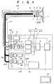
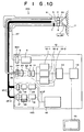
- the fluorescence observing apparatus comprises (1) a light source section 100 equipped with an excitation light source and a visible light (white light) source; (2) a flexible endoscope 200 for forming a normal image obtained by irradiating white light Wh guided from the light source section 100, to the tissue of an organism and also propagating the image of fluorescence (obtained by irradiating excitation light Le likewise guided from the light source section 100, to the tissue) to an optical fiber; (3) an image taking-in section 300 for taking in and storing the normal image and fluorescence image obtained by the endoscope 200, as image signals; (4) an image computing memory 13 equipped with the computation function of discriminating a cancerous tissue and a normal tissue by receiving and computing the image signals stored in the image taking-in section 300 and the storage function of storing and outputting the result of discrimination as an image signal; (5) a video
- the white light source 19 of the light source section 100 is connected to a white-light power source 20 that is controlled by the control section 16, and the white light source 19 emits white light Wh at cycles of 1/60 sec.
- the white light Wh is focused by a white-light condenser lens 22 and is incident on a white-light guide 25-1.
- the white-light guide 25-1 is formed with a multicomponent glass fiber and connected to the light source section 100.
- the excitation light source 19 of the light source section 100 employs an InGaN semiconductor laser of multi-quantum cell structure (active layer InGaN/InGaN).
- the excitation light source 19 is pulse-driven by an LD power source 20 that is controlled by the control section 16, and emits pulsed excitation light Le at cycles of 1/60 sec.
- the excitation light Le is focused by an excitation-light condenser lens 21 and is incident on an excitation-light guide 25-2.
- the excitation-light guide 25-2 is formed with a silica glass fiber and connected to the light source section 100.
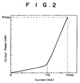
- the semiconductor laser employed in the excitation light source 17 has a continuous maximum output (continuous maximum rated output) of Pmax (mW), a continuous maximum operating current of Imax (mA), an oscillating wavelength of 410 nm (single mode), and an oscillating threshold current of Ith (mA) (Ith ⁇ Imax), as shown in Fig. 2.
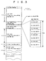
- the structure and composition of the excitation light source 17 are shown in Fig. 3.
- the white-light guide 25-1 and the excitation-light guide 25-2 are bundled integrally in cable form.
- the white-light guide 25-1 and the excitation-light guide 25-2 bundled integrally in cable form are inserted and disposed so that excitation light Le or white light Wh is irradiated toward a sample 1 (tissue 1) through an illuminating lens 5.
- the image (normal image) of the tissue 1 illuminated with white light Wh is formed on the light receiving surface of a normal-observation charge-coupled device (CCD) imager 7 through a normal-observation objective lens 6.
- CCD charge-coupled device
- the image of fluorescence Ke which occurs from the sample 1 when excitation light Le is irradiated, is formed on an end face Ki of a fluorescence image fiber 26 through a fluorescence-observation objective lens 4.
- the fluorescence image propagates along the fluorescence image fiber 26 and is guided to the other end face Ko of the fluorescence image fiber 26 connected to the image taking-in section 300.
- the image taking-in section 300 is provided with a normal observation A/D converter 8 for converting the electrical image signal transmitted by the CCD cable 27, to a digital image signal and a normal image memory 9 for storing the digital image signal.
- the image taking-in section 300 is further provided with a fluorescence observation high-sensitivity CCD imager 10 (cooling-type back irradiation CCD imager); an optical system constructed so that the fluorescence image guided to the end face Ko of the fluorescence image fiber 26 is formed on the light receiving surface of the fluorescence observation high-sensitivity CCD imager 10 by a fluorescence condenser lens 23 through an excitation-light cut filter 24 for cutting off a wavelength less than or equal to a wavelength of near 4100 nm; a fluorescence observation A/D converter 11 for converting the electrical image signal, received and converted by the fluorescence observation high-sensitivity CCD imager 10, to a digital image signal; and a fluorescence image memory 12, which
- the light receiving surface of the fluorescence observation high-sensitivity CCD imager 10 has a color mosaic filter 10a such as the one shown in Fig. 5.
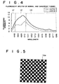
- the color mosaic filter 10a consists of sets with three kinds of filters, and the filters respectively have characteristics of transmitting only light which has a wavelength belonging to a wavelength region h1 (near 430 nm to near 445 nm), light which has a wavelength belonging to a wavelength region h2 (near 445 nm to near 520 nm), and light which has a wavelength belonging to a wavelength region h3 (near 520 nm to near 700 nm), shown in Fig. 4.
- the fluorescence image is separated into the wavelength bands of the 3 regions shown in Fig. 4 and is received.
- the fluorescence observing apparatus of the first embodiment is controlled by the controller 16 in accordance with a timing chart shown in Fig. 6.
- white light Wh emitted from the white light source 19 is guided to the endoscope 200 through the white-light condenser lens 22 and the white-light guide 25-1 and illuminates the tissue 1 through the illuminating lens 5.
- the image of the tissue 1 illuminated with the white light Wh is formed on the light receiving surface of the normal observation CCD imager 7 by the normal-observation objective lens 6 and is exposed to the photosensitive portion of the normal-observation CCD imager 7 which consists of a plurality of photosensitive elements for converting light to electric charge.
- the image of the tissue 1 is converted to signal charge and accumulated.
- the signal charges accumulated in the photosensitive portion are converted to an electrical image signal by a circuit constituting the normal observation CCD imager 7, and the electrical image signal is read out.
- the electrical image signal is converted to a digital signal by the normal observation A/D converter 8 and is stored in the normal image memory 9.
- pulsed excitation light Le emitted from the excitation light source 17 is guided to the endoscope 200 through the excitation light condenser lens 21 and the excitation light guide 25-2 and is irradiated toward the tissue 1 through the illuminating lens 5.
- the fluorescence emitted from the tissue 1 by irradiation of the excitation light Le, is formed on the end face Ki of the fluorescence image fiber 26 by the fluorescence image objective lens 4 and is propagated to the other end face Ko.
- the excitation light Le contained in the fluorescence Ke (which is a measuring object) is removed by an excitation-light cut filter 24.
- the fluorescence image is formed on the light receiving surface of the fluorescence observation high-sensitivity CCD imager 10 having the mosaic filter 10a by the fluorescence condenser lens 23 and is exposed to the photosensitive portion of the fluorescence observation high-sensitivity CCD imager 10 and is accumulated as signal charge.
- the signal charges accumulated in the photosensitive portion are converted to an electrical image signal by a circuit constituting the fluorescence observation high-sensitivity CCD imager 10, and the electrical image signal is read out.
- the electrical image signal is converted to a digital signal by the fluorescence observation A/D converter 11 and is stored in the fluorescence image h1 memory 12-1, the fluorescence image h2 memory 12-2, and the fluorescence image h3 memory 12-3.
- the intensity value of the fluorescence, transmitted through the filter h1 of the mosaic filter 10a, and converted to a digital value by the fluorescence observation A/D converter 11, is stored in the fluorescence image h1 memory 12-1. Also, the intensity value of the fluorescence, transmitted through the filter h2 of the mosaic filter 10a, and converted to a digital value by the fluorescence observation A/D converter 11, is stored in the fluorescence image h2 memory 12-2. Furthermore, the intensity value of the fluorescence, transmitted through the filter h3 of the mosaic filter 10a, and converted to a digital value by the fluorescence observation A/D converter 11, is stored in the fluorescence image h3 memory 12-3.
- This semiconductor laser is driven so that the integrated value of the oscillating output values per unit time is less than or equal to the integrated value of the continuous maximum output values per unit time, and a pulse oscillation duty ratio is set so that a peak value greater than or equal to the continuous maximum output is obtained.
- Pmax mW
- energy E equivalent to the integrated value of the oscillating output values of each pulse per unit time needs to be set to a value less than or equal to the integrated value J of the continuous maximum output values per unit time. Since the unit time is 1/60 sec, it becomes necessary to meet the conditions shown below.
- Peak value Pp (mW) ⁇ (1000/0.5) ⁇ (Pmax/60) Peak value Pp (mW) ⁇ (2000/60) ⁇ (Pmax/60)
- Pulse width Wd (sec) ⁇ (1/Pp) ⁇ (Pmax/60) Pulse width Wd (sec) ⁇ Pmax/(60 ⁇ Pp)
- InGaN is less by a factor of 10 -10 in dislocation mobility at the same temperature than InGaAsP and GaAs.
- a condition of oscillation has been alleviated because the active layer has a multi-quantum cell structure of InGaN/InGaN (i.e., luminous efficiency has been enhanced by reducing the oscillating threshold current to make temperature dependency lower).
- the pulse drive makes the generation of heat intermittent and increases the radiating time. Therefore, because of heat generated by a crystal, doping materials, such as Mg, etc., are prevented from diffusing thermally and crossing and short-circuiting the active layer. As a result, device degradation can be prevented and device lifetime can be prolonged.
- timing chart of Fig. 6 in order to take in a normal image and a fluorescence image and obtain a dynamic image from them, it is necessary that excitation light Le and white light Wh be exposed by setting timing so that the irradiation of excitation light Le to the tissue 1 and the irradiation of white light Wh to the tissue 1 do not overlap within a period of 1/60 sec. For instance, timing needs to be set so that the irradiation of excitation light Le to the tissue 1 and the exposure of fluorescence emitted from the tissue 1 are executed during the time that the irradiation of white light Wh stops, and the time that the normal observation CCD imager 7 is in the vertical blanking period.
- the accumulated signal charges are moved and saved in a circuit other than the photosensitive portion constituting the CCD imager, and the saved signal charges are then read out. Therefore, since signal charges can be read out during a sufficient time of 1/60 sec until signal charges in the next cycle are read out, an image signal with less noise can be obtained.
- the values of the image signals, stored in the fluorescence image h1 memory 12-1, the fluorescence image h2 memory 12-2, and the fluorescence image h3 memory 12-3, are output to the image computing memory 13 and given the following computing process.
- the mosaic filter 10a consists of a large number of matrix blocks having four microregions.
- a filter h1, filters h2, and a filter h3 having a wavelength transmission characteristic such as that shown in Fig. 4 are disposed. More specifically, the filter h1, the filters h2, and the filter h3 respectively transmit only light which has a wavelength belonging to a wavelength region h1, light which has a wavelength belonging to a wavelength region h2, and light which has a wavelength belonging to a wavelength region h3.
- the filter h1 corresponds to the microregion M11(1, 1), the filters h2 to the microregions M11(1, 2) and M11(2, 1), and the filter h3 to the microregion M11(2, 2). Since it is generally known that, as shown in Fig. 4, at the wavelength region h2 a normal tissue is different in profile from a cancerous tissue, a discrimination between a normal tissue and a cancerous tissue becomes possible by dividing the fluorescence intensity at the wavelength h2 by the fluorescence intensity at the overall wavelength region.
- the discrimination value calculated in the above-mentioned manner is obtained for all the blocks of the mosaic filter 10a, that is, M11, M12, M13, M14, ⁇ .
- the discrimination value is compared with a reference discrimination value ST calculated in the same manner as the aforementioned method from a tissue judged a cancerous tissue or normal tissue, whereby a degree of difference can be obtained as a value.
- the differential discrimination value SS calculated as described above is output from the image computing memory 13 and is input to the video signal processing circuit 14 along with the value of the image signal of the normal image outputted from the normal image memory 9. These signal values are processed so that the normal image and the fluorescence image are simultaneously displayed on a single screen, and are output and displayed on the display section 15 as information that is used for diagnosing a morbid part.
- a 1-stage Peltier element 28 is disposed in direct contact with the excitation light source 17 to cool the operating temperature of the InGaN semiconductor laser of multi-quantum cell structure (active layer InGaN/InGaN) to 10°C or less, the oscillating threshold current decreases in accordance with temperature. As a result, the lifetime of the semiconductor laser can be considerably prolonged and a higher peak value can be obtained without limiting the maximum output at thermal saturation. Furthermore, if a multi-stage Peltier element is employed to cool the above-mentioned operating down to - 20°C, the above-mentioned effect can be further enhanced.
- the InGaN semiconductor laser of multi-quantum cell structure active layer InGaN/InGaN
- the above-mentioned same effect which is superior to the conventional case can be obtained even in other InGaN-based semiconductor lasers and GaN-based semiconductor lasers.
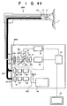
- Fig. 11 illustrates a second embodiment of the fluorescence observing apparatus constructed according to the present invention.
- the present invention is applied to a fluorescence endoscope for diagnosing the localization of a morbid part from a difference in the emitted state of the fluorescence emitted from a tissue absorbing photofurin II (which is a photosensitive dye) by irradiating excitation light to the tissue.
- a fluorescence endoscope for diagnosing the localization of a morbid part from a difference in the emitted state of the fluorescence emitted from a tissue absorbing photofurin II (which is a photosensitive dye) by irradiating excitation light to the tissue.
- an excitation light source 17 employs an InGaN semiconductor later of multi-quantum cell structure (active layer InGaN/InGaN) of oscillating wavelength 400 nm and is pulse-operated with a dc bias current greater than or equal to an oscillating threshold current Ith (mA).
- the pulse oscillation of the above-mentioned semiconductor laser is driven so that, as shown in Fig. 12, the integrated value Bo of the output values per unit time (per 1/60 sec) of LED light (spontaneous emission light), which occurs by dc bias current, and the integrated value Eo of the pulse oscillation output values per unit time become less than or equal to the integrated value Jo of the continuous maximum output values per unit time, and the pulse oscillation duty ratio is set so that a peak value greater than or equal to the continuous maximum output value is obtained. That is, the pulse oscillation duty ratio is set so that Eo + Bo ⁇ Jo.
- the above-mentioned semiconductor laser is capable of oscillating a wavelength between ultraviolet and visible regions, optimum wavelength can be selected according to the excitation wavelength of a photosensitive pigment to be assumed.
- an endoscope 200 has no CCD imager and therefore a normal image and a fluorescence image are both propagated to an image taking-in section 300 by an image fiber 25.
- the image taking-in section 300 is provided with a disc filter 29 which is rotated by a motor 30, a normal observation CCD imager 7 for forming the image of a tissue 1 illuminated with white light Wh, and a fluorescence observation high-sensitivity CCD imager 8 for forming the image of fluorescence emitted from the tissue 1 by irradiation of excitation light Le.
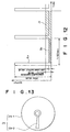
- the filter 29 is provided with a reflection region 29-1 for reflecting light which has a wavelength belonging to a wavelength region necessary for observation of a normal image and a transmission region 29-2 for transmitting light which has a wavelength belonging to a wavelength region necessary for observation of a fluorescence image, as shown in Fig. 13.
- the remaining construction of the second embodiment is the same as the first embodiment.
- a normal image which is obtained when the tissue 1 is being illuminated with white light Wh, is reflected by the reflection region 29-1 of the filter 29 and formed on the light receiving surface of the normal observation CCD imager 7.
- a fluorescence image which is obtained when excitation light Le is irradiating the tissue 1, is transmitted through the transmission region 29-2 of the filter 29 and formed on the light receiving surface of the fluorescence observation high-sensitivity CCD imager 10.
- the normal image formed on the light receiving surface of the normal observation CCD imager 7 is converted to signal charge and further to an image signal and is output to a normal observation A/D converter 8, in which it is converted to a digital value.
- the digital value is stored in a normal image memory 9.
- the fluorescence image formed on the light receiving surface of the fluorescence observation high-sensitivity CCD imager 10 is converted to signal charge and further to an image signal and is output to a fluorescence observation A/D converter 11, in which it is converted to a digital value.
- the digital value is stored in a fluorescence image memory 12.
- the image signals, stored in the normal image memory 9 and the fluorescence image memory 12, are input to a video signal processing unit 14.
- the input image signals are processed so that the normal image and the fluorescence image are simultaneously displayed on a single screen, and the signals are output and displayed on the display section 15 as information that is used for diagnosing the localization of a morbid part.
- the remaining construction and operation of the second embodiment are the same as the first embodiment.
- the temperature controlling system in which the Peltier element 28 described complementarily in the aforementioned first embodiment is disposed in direct contact with the excitation light source 17
- the temperature controlling system be a system for fixing a semiconductor laser 42 in direct contact with a cooling plate 28a extending from the Peltier element 28, hermetically sealing the laser 42 with a cover 28b, and introducing nitrogen into the inside of the cover 28b, as shown in Fig. 14.
- Fig. 15 illustrates a third embodiment of the fluorescence observing apparatus constructed according to the present invention, parts with a function similar to the first embodiment being shown with the same reference numerals and characters as the first embodiment.
- a fluorescence observing apparatus 800 in the third embodiment is the same as the first embodiment, except that the construction of a mosaic filter to be mounted on the light receiving surface of a fluorescence observation high-sensitivity CCD imager 10 is varied and the fluorescence image h3 memory 12-3 of the first embodiment is removed.
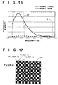
- the mosaic filter 10b in the third embodiment consists of a plurality of sets of two kinds, a filter h1 and a filter h2, arranged in lattice form, as shown in Fig. 17.
- the filter h1 and the filter h2 have a wavelength transmission characteristic such as the one shown in Fig. 16.
- the filter h1 and the filter h2 transmit light which has a wavelength belonging to a wavelength region h1 (near 430 nm to near 740 nm) and light which has a wavelength belonging to a wavelength region h2 (near 445 nm to near 520 nm), respectively.
- the fluorescence observing apparatus of the third embodiment is controlled by a controller 16 in accordance with a timing chart shown in Fig. 18.
- pulsed excitation light Le formed from 3 divided pulses having the same rectangular waveform, is emitted from an excitation light source 17.
- the excitation light Le is guided to an endoscope 200 through an excitation light condenser lens 21 and an excitation light guide 25-2 and is irradiated toward a tissue 1 through an illuminating lens 5.
- the fluorescence emitted from the tissue 1 by irradiation of the excitation light Le, is formed on an end face Ki of a fluorescence image fiber 26 by an fluorescence image objective lens 4 and is propagated to the other end face Ko.
- the excitation light Le contained in the fluorescence Ke (which is a measuring object) is removed by an excitation-light cut filter 24.
- the fluorescence image is formed on the light receiving surface of a fluorescence observation high-sensitivity CCD imager 10 having the mosaic filter 10b by a fluorescence condenser lens 23 and is exposed.
- the fluorescence image is accumulated in the photosensitive portion of the fluorescence observation high-sensitivity CCD imager 10 as signal charge.
- the signal charges accumulated in the photosensitive portion are converted to an electrical image signal by a circuit constituting the fluorescence observation high-sensitivity CCD imager 10, and the electrical image signal is read out.
- the electrical image signal is converted to a digital value by a fluorescence observation A/D converter 11 and is stored in a fluorescence image h1 memory 12-1 and a fluorescence image h2 memory 12-2.
- the intensity value of the fluorescence, transmitted through the filer h1 of the mosaic filter 10b, and converted to a digital value by the fluorescence observation A/D converter 11, is stored in the fluorescence image h1 memory 12-1. Also, the intensity value of the fluorescence, transmitted through the filter h2 of the mosaic filter 10b, and converted to a digital value by the fluorescence observation A/D converter 11, is stored in the fluorescence image h2 memory 12-2.
- the operating conditions of the InGaN semiconductor laser of multi-quantum cell structure employed in the excitation light source 17 will be described in detail.
- This semiconductor laser is driven so that the integrated value of the oscillation output values per unit time is less than or equal to the integrated value of the continuous maximum output values per unit time, and the pulse oscillation duty ratio is set so that a peak value greater than or equal to the continuous maximum output value is obtained.
- energy E equivalent to the integrated value of the oscillation output values of the pulsed excitation light per unit time needs to be set to a value less than or equal to the integrated value J of the continuous maximum output values per unit time.
- Peak value Pp (mW) ⁇ ⁇ ⁇ 5.6 ⁇ 10 2 because the above-mentioned value multiplied by a safe factor (0 ⁇ ⁇ ⁇ 1) is set as the peak value so that the semiconductor is not destroyed.
- the values of the image signals, obtained under the aforementioned setting of the pulsed excitation light, and stored in the fluorescence image h1 memory 12-1 and the fluorescence image h2 memory 12-2, are output to the image computing memory 13, in which the following computing process is performed.
- the mosaic filter 10b consists of a large number of matrix blocks having four microregions.
- filters h1 and filters h2 having the wavelength transmission character shown in Fig. 16 are disposed.
- the filter h1 and the filter h2 respectively transmit only light which has a wavelength belonging to a wavelength region h1 and light which has a wavelength belonging to a wavelength region h2.
- the filters h1 correspond to the microregions M11(1, 1) and M11(2, 2) and the filters h2 correspond to the microregions M11(1, 2) and M11(2, 1).
- the discrimination value calculated in the above-mentioned manner is obtained for all the blocks of the mosaic filter 10b, that is, M11, M12, M13, M14, ⁇ .
- the discrimination value is compared with a reference discrimination value ST calculated in the same manner as the aforementioned manner from a tissue judged to be a cancerous tissue or normal tissue, whereby a degree of difference can be obtained as a value.
- the result is stored in the image computing memory 13 as a differential discrimination value SS.
- the differential discrimination value SS calculated as described above is output from the image computing memory 13 and is input to the video signal processing circuit 14 along with the value of the image signal of the normal image outputted from the normal image memory 9. These signal values are processed so that the normal image and the fluorescence image are displayed on different display sections 15a and 15b.
- the remaining operation of the third embodiment is the same as the first embodiment.
- the pulsed excitation light formed from 3 divided pulses having the same rectangular waveform
- the number of divided pulses is not limited to 3.
- the pulsed excitation light may be formed from a plurality of divided pulses.
- the pulse shape, the peak value, etc. may vary from pulse to pulse.
- the irradiation of the pulsed excitation light to the tissue in the first, the second, and the third embodiment does not always need to be performed during the time that the normal observation CCD imager 7 is in a vertical blanking period. However, if the irradiation of the pulsed excitation light is performed during the time that the normal observation CCD imager 7 is in a vertical blanking period, a fluorescence image and a normal image be can obtained with higher quality within a period of 1/60 sec (1 frame).
- Fig. 21 illustrates a fourth embodiment of the fluorescence observing apparatus constructed according to the present invention, and parts with a function similar to the first embodiment are shown with the same reference numerals and characters as the first embodiment.
- a fluorescence observing apparatus 800 of the fourth embodiment the construction of the mosaic filter mounted on the light receiving surface of the CCD imager in the first embodiment is varied so that a normal image and a fluorescence image are both formed by a CCD imager 10. For this reason, the components for observation of a normal image, such as the normal observation objective lens 6, normal observation CCD imager 7, and CCD cable 27 of the endoscope 200 and the normal observation A/D converter 8, normal image memory 9, etc., of the image taking-in section 300, are removed. The other components are similar to the first embodiment.
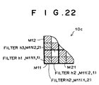
- a mosaic filter 10c in the fourth embodiment consists of a plurality of sets of a filter h1, filters h2, and a filter h3 arranged in lattice form such as that shown on an enlarged scale in Fig. 22.
- the filter h1 and the filter h2 have a wavelength transmission characteristic such as the one shown in Fig. 16, described in the third embodiment. That is, the filter h1 and the filter h2 transmit light which has a wavelength belonging to a wavelength region h1 (near 430 nm to near 750 nm) and light which has a wavelength belonging to a wavelength region h2 (near 445 nm to near 520 nm), respectively.
- the filter h3 transmits visible light (white light).
- the filter h1 corresponds to the microregion M11(1, 1)
- the filters h2 to the microregions M11(1, 2) and M11(2, 1)
- the filter h3 to the microregion M11(2, 2).
- the image signals, passed through the filter h1 and the filters h2, and formed and outputted by the CCD imager 10, are converted to digital values by the A/D converter 11.
- the digital values are stored in the fluorescence image h1 memory 12-1 and the fluorescence image h2 memory 12-2 and are then output to the image computing memory 13, in which the following computing process is performed.
- the discrimination value calculated in this manner is obtained for all the blocks of the mosaic filter 10c, that is, M11, M12, M13, M14, ⁇ .
- the discrimination value is compared with a reference discrimination value ST beforehand calculated from a tissue judged to be a cancerous tissue or normal tissue, whereby a degree of difference with the cancerous tissue or normal tissue can be calculated as a value.
- the result is stored in the image computing memory 13 as a differential discrimination value SS.
- the intensity of visible light transmitted through the filter h3 is obtained as signal charge by the photosensitive element corresponding to M11(2, 2).
- the signal charge is converted to a digital image signal D11(2, 2) by the fluorescence observation A/D converter 11.
- the digital image signal D11(2, 2) is stored in the fluorescence image h3 memory 12-3 and is then output and stored in the image computing memory 13.
- the differential discrimination value SS calculated in the aforementioned manner and stored in the image computing memory 13, and the value of the image signal, representing a normal image illuminated with visible light, are both input to the video signal processing circuit 14. These signal values are processed so that the normal image and the fluorescence image are displayed on different display sections 15a and 15b, respectively.
- the remaining operation of the fourth embodiment is similar to the first embodiment.
- the on-chip CCD imager 10 with the mosaic filter 10c may be disposed in the endoscope 200, as shown in Fig. 23, so that a fluorescence image formed by a fluorescence image objective lens 4 can be formed directly by the CCD imager 10 without being passed through the aforementioned fluorescence image fiber 26.
- the above-mentioned optical system for forming the image of the tissue in order to easily dispose the CCD imager 10 within the endoscope 200, is constructed such that the image of the tissue 1 propagated by the fluorescence observation objective lens is changed by approximately 90 degrees in direction by a prism 31 so that it is formed on the CCD imager 10.
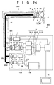
- Fig. 24 illustrates a fifth embodiment of the fluorescence observing apparatus constructed according to the present invention, and parts with a function similar to the first embodiment are shown with the same reference numerals and characters as the first embodiment.
- a fluorescence observing apparatus 800 in the fifth embodiment includes 10 (ten) InGaN semiconductor lasers of quantum cell structure (luminescent layer InGaN/InGaN) as an excitation light source 17.
- the direction of an optical path for propagating the image of a tissue 1 is changed by approximately 90 degrees by a prism 41 so that the tissue image is formed on a normal observation CCD imager 7.
- the normal observation CCD imager 7 can be easily disposed within an endoscope 200.
- the remaining construction of the fifth embodiment is the same as the first embodiment.
- micro lens 43 are attached to the exit apertures of the semiconductor lasers 42 so that the excitation light Le emitted from each semiconductor laser 42 can be emitted as a collimated beam of light. Then, the collimated light beams are focused by an excitation light condenser lens 21 and incident on an end face Ri of an excitation light guide 25-2.
- the semiconductor laser is pulse-driven by the control section 16 to irradiate the pulsed excitation light Le at cycles of 1/60 sec
- the semiconductor lasers are not pulse-driven. That is, instead of performing the pulse drive of generating an output exceeding the continuous maximum output (continuous maximum rated output) by a method such as a Q-switch, pulsed excitation light is emitted by alternately producing an ON state in which the laser is being oscillated with an output within the continuous maximum output by performing continuous oscillation drive (hereinafter called CW drive) and an OFF state in which oscillation of the laser stops (or by switching on and off CW drive).
- CW drive continuous oscillation drive
- the fluorescence observing apparatus of the fifth embodiment is controlled by a control section 16 in accordance with a timing chart shown in Fig. 26.
- the white light visible light
- a white light source 19 irradiates a tissue 1 for about 1/30 sec in a period of frame 1.
- a fluorescence image received during a period of frame 2 is read out as an image signal.
- the excitation light emitted from the excitation light source 17 by the CW drive irradiates the tissue 1 for about 1/30 sec in a period of frame 2.
- the fluorescence emitted from the tissue 1 by this irradiation of excitation light Le is formed on a mosaic filter 10a mounted on the light receiving surface of a fluorescence observation high-sensitivity CCD imager 10 and is exposed.
- the fluorescence is accumulated as signal charge in the photosensitive portion of the fluorescence observation high-sensitivity CCD imager 10.
- the signal charges accumulated in the photosensitive portion are converted to an electrical image signal by a circuit constituting the fluorescence observation high-sensitivity CCD imager 10 within a period of frame 3, and the electrical image signal is read out.
- a fluorescence image and a normal image can be obtained as a dynamic image of 1 frame/(1/15) sec by alternately irradiating the white light Wh and the excitation light Le at cycles of a period of about 1/30 sec.
- the remaining operation in the fifth embodiment is the same as the first embodiment.
- a rotating filter 44 such as that shown in Fig. 27 may be used instead of using the mosaic filter 10a mounted on the light receiving surface of the fluorescence observation high-sensitivity CCD imager 10.
- the rotating filter 44 has 120-degree fan filters h1, h2, and h3 equipped with the same wavelength transmission characteristic as the mosaic filter 10a, and therefore, the fan filters h1, h2, and h3 respectively transmit light which has a wavelength belonging to a wavelength region h1 (near 430 nm to near 445 nm), light which has a wavelength belonging to a wavelength region h2 (near 445 nm to near 520 nm), and light which has a wavelength belonging to a wavelength h3 (near 520 nm to near 750 nm).
- the rotating filter 44 is mounted on the rotating shaft of a motor 45 and interposed between the fluorescence observation high-sensitivity CCD imager 10 and the fluorescence observation condenser lens 23.
- the rotating filter 44 is rotated so that it makes one revolution in 1/30 sec. In this way, the fluorescence, which is incident on the light receiving surface of the fluorescence observation high-sensitivity CCD imager 10 during periods of even frames such as frame 2, frame 4, etc., in the timing chart of Fig. 26, can be separated into its spectral components and imaged in a time-divided manner.
- a rotating filter 44' such as the one shown in Fig. 29 may be employed.
- the rotating filter 44' has 60-degree fan filters h1, h2, and h3 equipped with the same wavelength transmission characteristic as the aforementioned filter and further has a semicircular filter h4.
- the rotating filter 44' is mounted on the rotating shaft of the motor 45 and interposed between the fluorescence observation high-sensitivity CCD imager 10 and the fluorescence observation condenser lens 23.
- the rotating filter 44 is rotated so that it makes one revolution in 1/15 sec. In this way, the fluorescence, which is incident on the light receiving surface of the fluorescence observation high-sensitivity CCD imager 10 during periods of even frames such as frame 2, frame 4, etc., in the timing chart of Fig.
- the filter h4 can transmit the wavelength region of visible light and form a normal image.
- the components for forming a normal image such as the normal observation objective lens 6, the normal observation CCD imager 7, etc., become unnecessary.
- the image signal which represents the normal image formed and outputted by the fluorescence observation high-sensitivity CCD imager 10 through the filter h4 in the rotating filter 44', is input to the normal observation A/D converter 8 and is output to the video signal processing circuit 14 via the normal image memory 9.
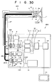
- Fig. 30 illustrates a sixth embodiment of the fluorescence observing apparatus constructed according to the present invention, parts with a function similar to the fifth embodiment being shown with the same reference numerals and characters as the fifth embodiment.
- the fluorescence observing apparatus 100 in the sixth embodiment is the same as the fifth embodiment, except that a rotating light-source filter 47 mounted on the rotating shaft of a motor 46 is interposed between an excitation light condenser lens 21 and an excitation light source 17.
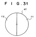
- the rotating light-source filter 47 has a semicircular filter f1 for transmitting light of near 430 nm to near 750 nm and a semicircular filter f2 for intercepting light.
- the rotating light-source filter 47 is rotated by a motor 46 so that it makes one revolution in 1/15 sec.
- the pulsed excitation light is emitted by alternately producing an ON state in which the laser is being oscillated with an output within the continuous maximum output by performing CW drive of the excitation light source 17 consisting of 10 InGaN semiconductor lasers and an OFF state in which oscillation of the laser stops (or by switching on and off CW drive)
- the CW drive of 10 InGaN semiconductor lasers is always performed. That is, the pulsed excitation light is emitted, by switching on the CW drive at all times without switching the CW drive on or off and by rotating the rotating light-source filter 47 so that it makes one revolution in 1/15 sec.
- the white light source 19 and the excitation light source 17 of the light source section 100 are controlled by a control section 100 in accordance with the timing chart shown in Fig. 26, as in the aforementioned embodiments.
- the white light emitted from the white light source 19 irradiates a tissue 1 for about 1/30 sec of each of the odd frames including a period of frame 1.
- the excitation light being emitted from the excitation light 17 by performing CW drive at all times irradiates the tissue 1 for about 1/30 sec of each of the even frames including a period of frame 2.
- a fluorescence image and a normal image can be obtained as a dynamic image of 1 frame/(1/15) sec by alternately irradiating the white light Wh and the excitation light Le at cycles of a period of about 1/30 sec.
- the remaining operation in the sixth embodiment is the same as the fifth embodiment.
- Fig. 32 illustrates a seventh embodiment of the fluorescence observing apparatus constructed according to the present invention, parts with a function similar to the first embodiment being shown with the same reference numerals and characters as the first embodiment.
- the fluorescence observing apparatus 800 in the seventh embodiment is the same as the first embodiment, except that the components such as the white light source for irradiating white light Wh to the tissue 1, and the components such as the normal observation CCD imager for forming a normal image, are removed.
- the pulsed excitation light Le is irradiated to the tissue 1.
- continuous excitation light is irradiated to a sample (e.g., a tissue, etc.), by performing CW drive of the semiconductor laser of the excitation light source 17 at all times (i.e., without switching the CW drive on or off) and also without intermittently intercepting the excitation light emitted from the semiconductor laser, as in the above-mentioned sixth embodiment.
- a fluorescent image alone is formed and displayed.
- the remaining operation in the seventh embodiment is the same as the first embodiment.
- the active layer employs the InGaN semiconductor laser of InGaN/InGaN multi-quantum cell structure as the excitation light source, the same effect can be obtained even if other InGaN-based semiconductors laser or GaN-based semiconductor lasers are employed.
- GaN broad area type or GaN surface emission type semiconductor lasers may be employed as the aforementioned semiconductor laser.
- An inexpensive and high-output excitation light source can be obtained with these semiconductor lasers.
- the desired output can be obtained by employing an array type semiconductor laser having a plurality of laser-light emitting points, or by driving a plurality of semiconductor lasers in parallel, as shown in the fifth embodiment.
- the temperature controlling system described in the aforementioned first embodiment is applicable to each of the aforementioned embodiments, and the same effect as the first embodiment can be obtained.
- the fluorescence observing apparatus according to the present invention is applied to an endoscope for diagnosing cancerous tissues
- the fluorescence observing apparatus according to the present invention can also be applied to operation microscopes, colposcopes, etc., and is applicable for diagnosing morbid tissues other than cancerous tissues.
- the fluorescence observing apparatus equipped with a light source capable of irradiating high-output excitation light can be reduced in size and cost by optimizing the material of the semiconductor laser, the setting of the drive method, etc.
Landscapes
- Health & Medical Sciences (AREA)
- Life Sciences & Earth Sciences (AREA)
- General Health & Medical Sciences (AREA)
- Physics & Mathematics (AREA)
- Pathology (AREA)
- Engineering & Computer Science (AREA)
- Molecular Biology (AREA)
- Analytical Chemistry (AREA)
- General Physics & Mathematics (AREA)
- Immunology (AREA)
- Chemical & Material Sciences (AREA)
- Biophysics (AREA)
- Nuclear Medicine, Radiotherapy & Molecular Imaging (AREA)
- Biomedical Technology (AREA)
- Heart & Thoracic Surgery (AREA)
- Medical Informatics (AREA)
- Biochemistry (AREA)
- Surgery (AREA)
- Animal Behavior & Ethology (AREA)
- Public Health (AREA)
- Veterinary Medicine (AREA)
- Investigating, Analyzing Materials By Fluorescence Or Luminescence (AREA)
- Instruments For Viewing The Inside Of Hollow Bodies (AREA)
- Microscoopes, Condenser (AREA)
- Endoscopes (AREA)
- Closed-Circuit Television Systems (AREA)
- Semiconductor Lasers (AREA)
Applications Claiming Priority (4)
| Application Number | Priority Date | Filing Date | Title |
|---|---|---|---|
| JP19248799 | 1999-07-07 | ||
| JP19248799 | 1999-07-07 | ||
| JP2000114702 | 2000-04-17 | ||
| JP2000114702A JP2001078175A (ja) | 1999-07-07 | 2000-04-17 | 蛍光観察装置 |
Publications (2)
| Publication Number | Publication Date |
|---|---|
| EP1067376A2 true EP1067376A2 (fr) | 2001-01-10 |
| EP1067376A3 EP1067376A3 (fr) | 2001-06-06 |
Family
ID=26507343
Family Applications (1)
| Application Number | Title | Priority Date | Filing Date |
|---|---|---|---|
| EP00114428A Ceased EP1067376A3 (fr) | 1999-07-07 | 2000-07-05 | Appareil pour mesurer la fluorescence |
Country Status (3)
| Country | Link |
|---|---|
| US (1) | US7062311B1 (fr) |
| EP (1) | EP1067376A3 (fr) |
| JP (1) | JP2001078175A (fr) |
Cited By (6)
| Publication number | Priority date | Publication date | Assignee | Title |
|---|---|---|---|---|
| WO2005039403A1 (fr) * | 2003-10-27 | 2005-05-06 | Joel Gerardo Diaz Sanchez | Detection specifique de lesions produites par le virus du papillome humain dans le tractus genital feminin inferieur |
| EP1905344A4 (fr) * | 2005-07-15 | 2009-04-22 | Olympus Medical Systems Corp | Endoscope et dispositif endoscope |
| EP2333524A4 (fr) * | 2008-09-18 | 2013-03-27 | Shimadzu Corp | Détecteur d'images fluorescentes et procédé de détection d'images fluorescentes |
| RU2632993C2 (ru) * | 2016-04-04 | 2017-10-11 | Владимир Алексеевич Шульгин | Оптоволоконный коммутатор лазерного спектроанализатора |
| DE102004024494B4 (de) | 2004-05-16 | 2019-10-17 | Dürr Dental SE | Medizinische Kamera |
| US11805977B2 (en) | 2017-12-22 | 2023-11-07 | Olympus Corporation | Endoscope system and control method for endoscope system |
Families Citing this family (31)
| Publication number | Priority date | Publication date | Assignee | Title |
|---|---|---|---|---|
| US7172553B2 (en) * | 2001-05-16 | 2007-02-06 | Olympus Corporation | Endoscope system using normal light and fluorescence |
| NZ546918A (en) * | 2003-10-03 | 2009-01-31 | Amc Amsterdam | System and method for imaging the reflectance of a substrate |
| JP4546741B2 (ja) * | 2004-01-08 | 2010-09-15 | オリンパス株式会社 | 蛍光顕微鏡 |
| JP4520216B2 (ja) * | 2004-05-11 | 2010-08-04 | Hoya株式会社 | 蛍光観察内視鏡装置 |
| DE602005004332T2 (de) | 2004-06-17 | 2009-01-08 | Cadent Ltd. | Verfahren zum Bereitstellen von Daten im Zusammenhang mit der Mundhöhle |
| JP4917436B2 (ja) | 2004-10-25 | 2012-04-18 | オリンパス株式会社 | 内視鏡装置 |
| US9131861B2 (en) * | 2004-11-30 | 2015-09-15 | Academisch Medisch Centrum | Pulsed lighting imaging systems and methods |
| JP4575174B2 (ja) * | 2005-01-07 | 2010-11-04 | オリンパスメディカルシステムズ株式会社 | 内視鏡用挿入部及び内視鏡 |
| DE202005003411U1 (de) * | 2005-02-24 | 2006-07-06 | Karl Storz Gmbh & Co. Kg | Multifunktionales Fluoreszenzdiagnosesystem |
| WO2006098146A1 (fr) * | 2005-03-15 | 2006-09-21 | Olympus Medical Systems Corp. | Section d’insertion pour endoscope |
| JP4794916B2 (ja) * | 2005-06-16 | 2011-10-19 | オリンパスメディカルシステムズ株式会社 | 内視鏡および内視鏡システム |
| JP5114024B2 (ja) * | 2005-08-31 | 2013-01-09 | オリンパス株式会社 | 光イメージング装置 |
| US7486854B2 (en) * | 2006-01-24 | 2009-02-03 | Uni-Pixel Displays, Inc. | Optical microstructures for light extraction and control |
| JP4917330B2 (ja) * | 2006-03-01 | 2012-04-18 | 浜松ホトニクス株式会社 | 画像取得装置、画像取得方法、及び画像取得プログラム |
| JP4845590B2 (ja) * | 2006-05-22 | 2011-12-28 | オリンパス株式会社 | 内視鏡システム |
| US20130317295A1 (en) * | 2006-12-29 | 2013-11-28 | GE Inspection Technologies | Light assembly for remote visual inspection apparatus |
| JP2008198759A (ja) * | 2007-02-13 | 2008-08-28 | Seiko Epson Corp | レーザ光源、レーザ光源装置、照明装置、モニタ装置、及び画像表示装置 |
| JP4920473B2 (ja) * | 2007-03-30 | 2012-04-18 | プレサイスゲージ株式会社 | 光部品実装方法及び装置 |
| JP2009034224A (ja) * | 2007-07-31 | 2009-02-19 | Olympus Medical Systems Corp | 医療装置 |
| US20090236541A1 (en) * | 2008-03-24 | 2009-09-24 | General Electric Company | System and Methods for Optical Imaging |
| CA3162577C (fr) | 2008-05-20 | 2023-09-26 | University Health Network | Dispositif et procede pour imagerie et surveillance par fluorescence |
| US20140152801A1 (en) | 2009-10-28 | 2014-06-05 | Alentic Microscience Inc. | Detecting and Using Light Representative of a Sample |
| US9075225B2 (en) | 2009-10-28 | 2015-07-07 | Alentic Microscience Inc. | Microscopy imaging |
| US9041790B2 (en) | 2009-10-28 | 2015-05-26 | Alentic Microscience Inc. | Microscopy imaging |
| JP2013048792A (ja) * | 2011-08-31 | 2013-03-14 | Fujifilm Corp | 内視鏡装置 |
| US10502666B2 (en) | 2013-02-06 | 2019-12-10 | Alentic Microscience Inc. | Sample processing improvements for quantitative microscopy |
| US10231626B2 (en) * | 2013-03-15 | 2019-03-19 | The Regents Of The University Of California | Imaging system and method for fluorescence guided surgery |
| WO2014205576A1 (fr) | 2013-06-26 | 2014-12-31 | Alentic Microscience Inc. | Améliorations de traitement d'échantillon destinées à la microscopie |
| WO2016011534A1 (fr) | 2014-07-24 | 2016-01-28 | University Health Network | Collecte et analyse de données à des fins de diagnostic |
| WO2018008062A1 (fr) * | 2016-07-04 | 2018-01-11 | オリンパス株式会社 | Dispositif d'observation par fluorescence et dispositif d'endoscope pour observation par fluorescence |
| US11320380B2 (en) * | 2020-04-21 | 2022-05-03 | Sartorius Bioanalytical Instruments, Inc. | Optical module with three or more color fluorescent light sources and methods for use thereof |
Family Cites Families (16)
| Publication number | Priority date | Publication date | Assignee | Title |
|---|---|---|---|---|
| JPS5940830A (ja) | 1982-08-31 | 1984-03-06 | 浜松ホトニクス株式会社 | レ−ザ光パルスを用いた癌の診断装置 |
| CA2042075C (fr) * | 1991-05-08 | 2001-01-23 | Branko Palcic | Systeme d'imagerie endoscopique |
| US5323008A (en) * | 1992-03-23 | 1994-06-21 | Diatron Corporation | Fluorometer detection system |
| US5337328A (en) * | 1992-05-08 | 1994-08-09 | Sdl, Inc. | Semiconductor laser with broad-area intra-cavity angled grating |
| US5679152A (en) * | 1994-01-27 | 1997-10-21 | Advanced Technology Materials, Inc. | Method of making a single crystals Ga*N article |
| US6900465B2 (en) * | 1994-12-02 | 2005-05-31 | Nichia Corporation | Nitride semiconductor light-emitting device |
| US5647368A (en) | 1996-02-28 | 1997-07-15 | Xillix Technologies Corp. | Imaging system for detecting diseased tissue using native fluorsecence in the gastrointestinal and respiratory tract |
| JP3796635B2 (ja) * | 1996-03-06 | 2006-07-12 | 富士写真フイルム株式会社 | 蛍光検出装置 |
| US6125132A (en) * | 1997-04-28 | 2000-09-26 | Fuji Photo Film Co., Ltd. | Laser diode pumped solid state laser, fiber laser and fiber amplifier |
| JPH10335700A (ja) * | 1997-06-04 | 1998-12-18 | Toshiba Corp | 半導体発光素子およびその製造方法 |
| US6422994B1 (en) * | 1997-09-24 | 2002-07-23 | Olympus Optical Co., Ltd. | Fluorescent diagnostic system and method providing color discrimination enhancement |
| JPH11211658A (ja) * | 1998-01-28 | 1999-08-06 | Nippon Sanso Kk | ガス中の不純物の分光分析方法 |
| US6421363B1 (en) * | 1998-03-17 | 2002-07-16 | Marek A. Osinski | Semiconductor lasers and amplifiers with grating-induced anisotropic waveguide |
| JP3697903B2 (ja) * | 1998-07-06 | 2005-09-21 | 富士ゼロックス株式会社 | 面発光レーザおよび面発光レーザアレイ |
| EP1115424A1 (fr) * | 1998-08-28 | 2001-07-18 | Febit Ferrarius Biotechnology GmbH | Procede et dispositif de mesure pour la determination d'une pluralite d'analytes dans un echantillon |
| JP2001070227A (ja) * | 1999-07-07 | 2001-03-21 | Fuji Photo Film Co Ltd | 蛍光観察装置 |
-
2000
- 2000-04-17 JP JP2000114702A patent/JP2001078175A/ja active Pending
- 2000-07-05 EP EP00114428A patent/EP1067376A3/fr not_active Ceased
- 2000-07-06 US US09/611,229 patent/US7062311B1/en not_active Expired - Fee Related
Non-Patent Citations (1)
| Title |
|---|
| NAKAMURA S. ET AL.: "InGaN/GaN/AlGaN-Based laser diodes with modulation-doped strained-layer superlattices", JPN. J. APPL. PHYS., vol. 36, no. 12a, 1997, Japan, pages L1568 - L1571 * |
Cited By (8)
| Publication number | Priority date | Publication date | Assignee | Title |
|---|---|---|---|---|
| WO2005039403A1 (fr) * | 2003-10-27 | 2005-05-06 | Joel Gerardo Diaz Sanchez | Detection specifique de lesions produites par le virus du papillome humain dans le tractus genital feminin inferieur |
| DE102004024494B4 (de) | 2004-05-16 | 2019-10-17 | Dürr Dental SE | Medizinische Kamera |
| EP1905344A4 (fr) * | 2005-07-15 | 2009-04-22 | Olympus Medical Systems Corp | Endoscope et dispositif endoscope |
| US8500632B2 (en) | 2005-07-15 | 2013-08-06 | Olympus Medical Systems Corp. | Endoscope and endoscope apparatus |
| EP2333524A4 (fr) * | 2008-09-18 | 2013-03-27 | Shimadzu Corp | Détecteur d'images fluorescentes et procédé de détection d'images fluorescentes |
| US8575569B2 (en) | 2008-09-18 | 2013-11-05 | Shimadzu Corporation | Fluorescence imaging apparatus and method for detecting fluorescent image |
| RU2632993C2 (ru) * | 2016-04-04 | 2017-10-11 | Владимир Алексеевич Шульгин | Оптоволоконный коммутатор лазерного спектроанализатора |
| US11805977B2 (en) | 2017-12-22 | 2023-11-07 | Olympus Corporation | Endoscope system and control method for endoscope system |
Also Published As
| Publication number | Publication date |
|---|---|
| EP1067376A3 (fr) | 2001-06-06 |
| JP2001078175A (ja) | 2001-03-23 |
| US7062311B1 (en) | 2006-06-13 |
Similar Documents
| Publication | Publication Date | Title |
|---|---|---|
| US7062311B1 (en) | Fluorescence observing apparatus | |
| US6433345B1 (en) | Fluorescence observing apparatus | |
| US10863896B2 (en) | Endoscope system and fluorescence imaging method | |
| US6478732B2 (en) | Endoscope system | |
| EP2407087B1 (fr) | Système d'endoscope | |
| US8337400B2 (en) | Illumination device for use in endoscope | |
| EP2133021B1 (fr) | Dispositif de source lumineuse, appareil d'imagerie et appareil d'endoscope | |
| JP2023090982A (ja) | 内視鏡システム | |
| US20070213593A1 (en) | Endoscope system | |
| JP6467746B1 (ja) | 内視鏡システムおよび内視鏡システムの作動方法 | |
| JP2009056248A (ja) | 光源装置、および光源装置の駆動制御方法、並びに内視鏡 | |
| JP2009297290A (ja) | 内視鏡装置およびその画像処理方法 | |
| US6943332B2 (en) | Laser microscope and irradiating method | |
| JP2008028380A (ja) | レーザ光源装置及び画像表示装置 | |
| JP2010042153A (ja) | 照明装置およびこれを用いた内視鏡 | |
| JP6438062B2 (ja) | 内視鏡システム | |
| JP5526482B2 (ja) | 発光装置の駆動方法及び発光装置 | |
| JP4445745B2 (ja) | 内視鏡装置 | |
| US6693945B1 (en) | Scanning type laser microscope | |
| JPH10286235A (ja) | 内視鏡装置 | |
| JPH11318806A (ja) | 内視鏡装置 | |
| JPH10337271A (ja) | 蛍光内視鏡 | |
| JP5219358B2 (ja) | 電子内視鏡装置 | |
| JP2001212071A (ja) | パルス光励起蛍光観察装置 | |
| JP2020010891A (ja) | 内視鏡用照明装置および内視鏡システム |
Legal Events
| Date | Code | Title | Description |
|---|---|---|---|
| PUAI | Public reference made under article 153(3) epc to a published international application that has entered the european phase |
Free format text: ORIGINAL CODE: 0009012 |
|
| AK | Designated contracting states |
Kind code of ref document: A2 Designated state(s): DE FR GB |
|
| AX | Request for extension of the european patent |
Free format text: AL;LT;LV;MK;RO;SI |
|
| PUAL | Search report despatched |
Free format text: ORIGINAL CODE: 0009013 |
|
| AK | Designated contracting states |
Kind code of ref document: A3 Designated state(s): AT BE CH CY DE DK ES FI FR GB GR IE IT LI LU MC NL PT SE |
|
| AX | Request for extension of the european patent |
Free format text: AL;LT;LV;MK;RO;SI |
|
| 17P | Request for examination filed |
Effective date: 20010906 |
|
| AKX | Designation fees paid |
Free format text: DE FR GB |
|
| 17Q | First examination report despatched |
Effective date: 20061009 |
|
| RAP1 | Party data changed (applicant data changed or rights of an application transferred) |
Owner name: FUJIFILM CORPORATION |
|
| STAA | Information on the status of an ep patent application or granted ep patent |
Free format text: STATUS: THE APPLICATION HAS BEEN REFUSED |
|
| 18R | Application refused |
Effective date: 20080523 |