EP1067424A1 - Dispositif d'affichage, dispositif electronique et guide lumineux - Google Patents
Dispositif d'affichage, dispositif electronique et guide lumineux Download PDFInfo
- Publication number
- EP1067424A1 EP1067424A1 EP00900929A EP00900929A EP1067424A1 EP 1067424 A1 EP1067424 A1 EP 1067424A1 EP 00900929 A EP00900929 A EP 00900929A EP 00900929 A EP00900929 A EP 00900929A EP 1067424 A1 EP1067424 A1 EP 1067424A1
- Authority
- EP
- European Patent Office
- Prior art keywords
- polarized light
- light
- liquid crystal
- display device
- splitting plate
- Prior art date
- Legal status (The legal status is an assumption and is not a legal conclusion. Google has not performed a legal analysis and makes no representation as to the accuracy of the status listed.)
- Granted
Links
- 239000004973 liquid crystal related substance Substances 0.000 claims abstract description 158
- 230000003287 optical effect Effects 0.000 claims description 45
- 230000010287 polarization Effects 0.000 claims description 26
- 238000004040 coloring Methods 0.000 claims description 19
- 238000002834 transmittance Methods 0.000 claims description 15
- 230000005540 biological transmission Effects 0.000 claims description 11
- 239000003086 colorant Substances 0.000 claims description 7
- 230000000740 bleeding effect Effects 0.000 abstract description 29
- 238000000149 argon plasma sintering Methods 0.000 abstract description 21
- 230000002035 prolonged effect Effects 0.000 abstract description 7
- 238000009792 diffusion process Methods 0.000 description 30
- 210000004027 cell Anatomy 0.000 description 29
- 238000010276 construction Methods 0.000 description 23
- 239000000758 substrate Substances 0.000 description 18
- 239000011521 glass Substances 0.000 description 15
- 210000002858 crystal cell Anatomy 0.000 description 11
- 239000004820 Pressure-sensitive adhesive Substances 0.000 description 7
- 230000000694 effects Effects 0.000 description 7
- 239000010408 film Substances 0.000 description 6
- 238000004519 manufacturing process Methods 0.000 description 6
- 239000003795 chemical substances by application Substances 0.000 description 5
- 239000004986 Cholesteric liquid crystals (ChLC) Substances 0.000 description 4
- 239000011159 matrix material Substances 0.000 description 4
- 229920003023 plastic Polymers 0.000 description 4
- 238000000926 separation method Methods 0.000 description 4
- 239000011347 resin Substances 0.000 description 3
- 229920005989 resin Polymers 0.000 description 3
- 241001076195 Lampsilis ovata Species 0.000 description 2
- 229910052782 aluminium Inorganic materials 0.000 description 2
- XAGFODPZIPBFFR-UHFFFAOYSA-N aluminium Chemical compound [Al] XAGFODPZIPBFFR-UHFFFAOYSA-N 0.000 description 2
- 230000007423 decrease Effects 0.000 description 2
- 230000000149 penetrating effect Effects 0.000 description 2
- 239000002952 polymeric resin Substances 0.000 description 2
- 230000002265 prevention Effects 0.000 description 2
- 229920003002 synthetic resin Polymers 0.000 description 2
- 239000010409 thin film Substances 0.000 description 2
- 239000012780 transparent material Substances 0.000 description 2
- 239000004925 Acrylic resin Substances 0.000 description 1
- 229920000178 Acrylic resin Polymers 0.000 description 1
- 229920002799 BoPET Polymers 0.000 description 1
- 238000010521 absorption reaction Methods 0.000 description 1
- NIXOWILDQLNWCW-UHFFFAOYSA-N acrylic acid group Chemical group C(C=C)(=O)O NIXOWILDQLNWCW-UHFFFAOYSA-N 0.000 description 1
- 239000002390 adhesive tape Substances 0.000 description 1
- 238000013459 approach Methods 0.000 description 1
- 230000015572 biosynthetic process Effects 0.000 description 1
- 238000009826 distribution Methods 0.000 description 1
- 239000011888 foil Substances 0.000 description 1
- 238000010438 heat treatment Methods 0.000 description 1
- AMGQUBHHOARCQH-UHFFFAOYSA-N indium;oxotin Chemical compound [In].[Sn]=O AMGQUBHHOARCQH-UHFFFAOYSA-N 0.000 description 1
- 238000001746 injection moulding Methods 0.000 description 1
- 239000007788 liquid Substances 0.000 description 1
- 239000000463 material Substances 0.000 description 1
- 238000000034 method Methods 0.000 description 1
- 239000000049 pigment Substances 0.000 description 1
- 239000004033 plastic Substances 0.000 description 1
- 239000002985 plastic film Substances 0.000 description 1
- 229920006255 plastic film Polymers 0.000 description 1
- 239000004417 polycarbonate Substances 0.000 description 1
- 229920000515 polycarbonate Polymers 0.000 description 1
- 229920005668 polycarbonate resin Polymers 0.000 description 1
- 239000004431 polycarbonate resin Substances 0.000 description 1
- 229920001690 polydopamine Polymers 0.000 description 1
- 229920000098 polyolefin Polymers 0.000 description 1
- 239000004332 silver Substances 0.000 description 1
- 229910052709 silver Inorganic materials 0.000 description 1
- 230000003595 spectral effect Effects 0.000 description 1
- 239000000126 substance Substances 0.000 description 1
- XOLBLPGZBRYERU-UHFFFAOYSA-N tin dioxide Chemical compound O=[Sn]=O XOLBLPGZBRYERU-UHFFFAOYSA-N 0.000 description 1
- 229910001887 tin oxide Inorganic materials 0.000 description 1
Images






Classifications
-
- G—PHYSICS
- G02—OPTICS
- G02F—OPTICAL DEVICES OR ARRANGEMENTS FOR THE CONTROL OF LIGHT BY MODIFICATION OF THE OPTICAL PROPERTIES OF THE MEDIA OF THE ELEMENTS INVOLVED THEREIN; NON-LINEAR OPTICS; FREQUENCY-CHANGING OF LIGHT; OPTICAL LOGIC ELEMENTS; OPTICAL ANALOGUE/DIGITAL CONVERTERS
- G02F1/00—Devices or arrangements for the control of the intensity, colour, phase, polarisation or direction of light arriving from an independent light source, e.g. switching, gating or modulating; Non-linear optics
- G02F1/01—Devices or arrangements for the control of the intensity, colour, phase, polarisation or direction of light arriving from an independent light source, e.g. switching, gating or modulating; Non-linear optics for the control of the intensity, phase, polarisation or colour
- G02F1/13—Devices or arrangements for the control of the intensity, colour, phase, polarisation or direction of light arriving from an independent light source, e.g. switching, gating or modulating; Non-linear optics for the control of the intensity, phase, polarisation or colour based on liquid crystals, e.g. single liquid crystal display cells
- G02F1/133—Constructional arrangements; Operation of liquid crystal cells; Circuit arrangements
- G02F1/1333—Constructional arrangements; Manufacturing methods
- G02F1/1335—Structural association of cells with optical devices, e.g. polarisers or reflectors
-
- G—PHYSICS
- G02—OPTICS
- G02F—OPTICAL DEVICES OR ARRANGEMENTS FOR THE CONTROL OF LIGHT BY MODIFICATION OF THE OPTICAL PROPERTIES OF THE MEDIA OF THE ELEMENTS INVOLVED THEREIN; NON-LINEAR OPTICS; FREQUENCY-CHANGING OF LIGHT; OPTICAL LOGIC ELEMENTS; OPTICAL ANALOGUE/DIGITAL CONVERTERS
- G02F1/00—Devices or arrangements for the control of the intensity, colour, phase, polarisation or direction of light arriving from an independent light source, e.g. switching, gating or modulating; Non-linear optics
- G02F1/01—Devices or arrangements for the control of the intensity, colour, phase, polarisation or direction of light arriving from an independent light source, e.g. switching, gating or modulating; Non-linear optics for the control of the intensity, phase, polarisation or colour
- G02F1/13—Devices or arrangements for the control of the intensity, colour, phase, polarisation or direction of light arriving from an independent light source, e.g. switching, gating or modulating; Non-linear optics for the control of the intensity, phase, polarisation or colour based on liquid crystals, e.g. single liquid crystal display cells
- G02F1/133—Constructional arrangements; Operation of liquid crystal cells; Circuit arrangements
- G02F1/1333—Constructional arrangements; Manufacturing methods
- G02F1/1335—Structural association of cells with optical devices, e.g. polarisers or reflectors
- G02F1/133528—Polarisers
- G02F1/133536—Reflective polarizers
Definitions
- the present invention relates to a technical field of a display device such as a liquid crystal device, and more particularly to a technical field of a transflective monochrome or color display device capable of displaying while switching between a reflective display and a transmissive display, an electronic apparatus using such a display device, and a light guide plate suitable for use in such a display device.
- this applicant has proposed a transflective display device using, as a means to better the brightness in the reflective display, a polarized light splitter which causes the reflection of a linearly polarized light component running in a predetermined direction while allowing the transmission of a linearly polarized light component advancing in a direction perpendicular thereto (Japanese Patent Application No. 8-245346).
- a description will be made hereinbelow of a transflective display device using this polarized light splitter.
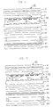
- a TN liquid crystal panel is composed of an upper polarizer 5130, an upper glass substrate 5302, a lower glass substrate 5304, a polarized light splitter 5160, a semipermeable light absorbing layer 5307 and a light source 5210.
- a TN liquid crystal placed between the upper glass substrate 5302 and the lower glass substrate 5304, is divided into a voltage non-applied area 5120 and a voltage applied area 5110.
- Incident light from the exterior of the display device turns through the upper polarizer 5130 to linearly polarized light in a direction parallel with the paper surface, and then form a linearly polarized light component in a direction perpendicular to the paper surface with its polarizing direction being twisted by 90° in the voltage non-applied section 5120 of the TN liquid crystal panel , and further is reflected on the polarized light splitter 5160 in a state of the same linearly polarized light in the direction perpendicular to the paper surface, and again undergoes a twist of 90° in its polarizing direction in the voltage non-applied section 5120 of the TN liquid crystal panel to develop into a linearly polarized light component in a direction parallel with the paper surface, finally going out of the upper polarizer 5130.
- the white display light is light reflected on the polarized light splitter 5160, which produces a brighter display than a conventional transflective display device.
- the light indicated by an optical path 5603 forms linearly polarized light in a direction parallel with the paper surface due to the upper polarizer 5130, and advances with its polarizing direction remaining intact even in the voltage applied section 5110 of the TN liquid crystal panel and with it remaining the same linearly polarized light in the direction parallel with the paper surface, and further transmits with its polarizing direction being also kept intact even in the polarized light splitter 5160, thereafter being absorbed by the semipermeable light absorbing layer 5307 to produce a black display.
- Light indicated by an optical path 5604 comes in through an opening section made in the semipermeable light absorbing layer 5307 and turns through the polarized light splitter 5160 to a linearly polarized light in a direction parallel with the paper surface and passes through the upper polarizer 5130 with its polarizing direction being kept intact even in the voltage applied section 5110 of the TN liquid crystal panel and with it remaining the same linearly polarized light parallel with the paper surface, thus providing a white display.
- the transflective display device Japanese Patent Application No. 8-245346
- Japanese Patent Application No. 8-245346 Japanese Patent Application No. 8-245346
- this applicant has proposed can accomplish more proper switching between a reflective display and a transmissive display in accordance with ON/OFF of a light source, which provides a relatively bright reflective display.
- a hole(s) is made in a portion of the reflecting layer or the reflecting layer is made relatively thin; whereupon, the reflecting layer has a permeable function to enable a transmissive display.
- the use of the polarized light splitter shown in Fig. 22 causes a positive-negative reversal phenomenon due to a difference between incidence on the polarized light splitter from the upper side and incidence from the lower side.
- the mode of the positive-negative reversal between a transmissive display and a reflective display creates a problem in that it is unsuitable for the display device depending on the applications of the display device, or is impracticable.
- the utilization efficiency of light drops, particularly at the transmissive display, it becomes dark.
- the SPD mode requires lowering reflectance of a reflecting layer, which leads to a dark reflective display. Conversely, if the reflectance of the reflecting layer is increased in order to brighten the reflective display, then a dark transmission display occurs, which requires the enhancement of back light luminance. As described above, with the conventional transflective color display device, extreme difficulty is encountered in accomplishing a bright good-looking color display not only at the reflective display and but also at the transmissive display.
- the present invention has been developed in consideration of the above-mentioned problems, and it is an object of the invention to provide, in transflective display devices using a polarization axis variable means, a transflective display device capable of preventing the positive-negative reversal between a reflective display relying on the external light and a transmissive display relying on lighting by a light source and further of achieving bright good-looking monochrome or color display, and further to provide an electronic apparatus using such a display device and a light guider suitable for use in such a display device.
- a display device comprising a liquid crystal panel in which a transmissive polarization axis is variable, first and second polarized light splitting plates located on respective sides of the liquid crystal panel to interpose the liquid crystal panel therebetween, a reflecting layer located on the opposite side of the second polarized light splitting plate with respect to the liquid crystal panel, a light source, a light guider interposed between the second polarized light splitting plate and the reflecting layer for guiding light from the light source so that the light is incident through the second polarized light splitting plate on the liquid crystal panel and further for allowing transmission of light from the second polarized light splitting plate side and transmission of light from the reflecting layer side, and a front scatterplate interposed between the liquid crystal panel and the reflecting layer for scattering forwardly each of light from the reflecting layer side toward the liquid crystal panel side and light from the liquid crystal panel side toward the reflecting layer side.
- the external light incident from the first polarized light splitting plate passes through the first polarized light splitting plate, the liquid crystal panel, the second polarized light splitting plate (for example, a polarizer or a reflecting polarizer), the front scatterplate and the light guider, and is then reflected on the reflecting plate to be outputted from the first polarized light splitting plate.
- the first polarized light splitting plate for example, a polarizer or a reflecting polarizer
- the light (for example, a linearly polarized light) polarized through the first polarized light splitting plate, the liquid crystal panel and the second polarized light splitting plate is scattered forwardly when passing through the front scatterplate to form white scattering light which in turn, is reflected on the reflecting layer.
- This reflected light is further scattered forwardly through the front scatterplate and, as white scattering light, passes through the second polarized light splitting plate, the liquid crystal panel and the first polarized light splitting plate to be outputted as the re-polarized light from the first polarized light splitting plate side.
- the term "forward scattering" signifies that the quantity of light scattered forwardly is larger than the quantity of light scattered rearwardly with respect to the advancing direction of incident light.
- the light source light emitted from the light source and guided by the light guider varies in its polarized state through the second polarized light splitting plate, the liquid crystal panel and the first polarized light splitting plate, thereby carrying out the display.
- This enables a bright display through the use of the light source light in a dark place.
- the front scatterplate is put between the liquid crystal panel and the light guider.
- the light source light emitted from the light source and guided by the light guider is scattered forwardly by the front scatterplate and is incident on the second polarized light splitting plate as white scattering light so that a display is made in a state where its polarized state varies through the second polarized light splitting plate, the liquid crystal panel and the first polarized light splitting plate.
- the distance between the front scatterplate and the liquid crystal panel is shorter; whereupon, the scattering plane of the front scatterplate which looks like the reflecting position in the reflective display in connection with that shortness approaches the liquid crystal panel.
- the double image or display bleeding due to the parallax caused by the distance between the front scatterplate and the liquid crystal panel is reducible.
- the reflected light of the external light is developed into white scattering light in the front scatterplate, shadow on the reflecting layer occurring due to the parallax stemming from the light guider reduces in a dark section displayed by being absorbed in the second polarized light splitting plate.
- the optical anisotropy in the light guider is so low that it hardly has influence on display chrominance non-uniformity in the display device.
- the corresponding optical anisotropy is high so that colored appearance of display or occurrence of chrominance non-uniformity is avoidable. Additionally, for prevention of such chrominance non-uniformity, if the optical scattering of the reflecting layer or the front scatterplate is made to step up, then the occurrence of a dark display is also avoidable.
- the optical axis direction is constant.
- the light guider contrary to the aforesaid mode in which the optical anisotropy of the light guider is low, the light guider has an optical anisotropy and the optical axis direction is constant, that is, it has a rule such as uniaxial or biaxial, which can eliminate the chrominance non-uniformity and enhance the contrast while enlarging the angle of field in display.
- a third polarized light splitting plate is additionally provided between the second polarized light splitting plate and the light guider.
- the aforesaid first polarized light splitting plate acts as a polarized light splitting plate which transmits, absorbs or reflects incident light in accordance with its polarized light component
- the aforesaid second polarized light splitting plate serves as a polarized light splitting plate which transmits, absorbs or reflects incident light in accordance with its polarized light component
- the aforesaid third polarized light splitting plate functions as a polarized light splitting plate which transmits or reflects incident light in accordance with its polarized light component, with the direction of the polarization axis of the second polarized light splitting plate coinciding approximately with the direction of the polarization axis of the third polarized light splitting plate.
- each of the first and second polarized light splitting plates is made, for example, from a polarizer.
- the third polarized light splitting plate for example composed of a reflecting polarizer, accepts the transmission of a linearly polarized light component of the incident light from the second polarized light splitting plate, assuming a direction coinciding approximately with the direction of the polarization axis of the second polarized light splitting plate, to the light guider side to output a portion of the incident light from the light guider to the second polarized light splitting plate side while reflecting the remaining portion thereof to the light guider side, thereby accomplishing polarization separation.
- the "the direction of the transmission axes coincide approximately" signifies that the angle made between the direction of these transmission axes is in the range of 0° to 40°, preferably in the range of 0° to 15°. Particularly, as the angle made between these polarization axis directions increases, the transmissive display becomes darker.
- the third polarized light splitting plate is a polarized light splitting plate which reflects, of the incident light, a linearly polarized light component in a direction substantially perpendicular to the direction of the polarization axis of the third polarized light splitting plate.
- the third polarized light splitting plate is a laminated member produced by piling up a plurality of layers closely, and the refractive indexes of the plurality of layers are equal to each other between adjacent layers in one predetermined direction while being different from each other in another direction perpendicular to that one predetermined direction.
- a linearly polarized light component in one predetermined direction reaches the other main surface on the opposite side in the state of the linearly polarized light component in that one predetermined direction, while a linearly polarized light component in another predetermined direction perpendicular to that one predetermined direction is reflected thereon as the linearly polarized light component.
- a linearly polarized light component in that one predetermined direction arrives at the opposite main surface side in a state of the linearly polarized light component in that one predetermined direction, while a linearly polarized light component in another predetermined direction perpendicular to that one predetermined direction is reflected thereon as the linearly polarized light component.
- the liquid crystal panel is composed of a TN liquid crystal element, an STN liquid crystal element or an ECB (Electrically Controlled Birefringence) liquid crystal element.
- this STN liquid crystal element includes an STN liquid crystal element using a color compensation optical anisotropic material. Additionally, if used as a liquid crystal element, such as an ECB liquid crystal element, having a birefringence effect, it is possible to vary the color development from the light source.
- a second display device comprising a liquid crystal panel in which a polarization axis is variable, first and second polarized light splitting plates located on respective sides of the liquid crystal panel to interpose the liquid crystal panel therebetween, a reflecting layer located on the opposite side of the second polarized light splitting plate with respect to the liquid crystal panel, a light source, and a light guider located between the second polarized light splitting plate and the reflecting layer for guiding light from the light source through the second polarized light splitting plate to the liquid crystal panel and further for allowing transmission of light from the second polarized light splitting plate side and light from the reflecting layer side, with the light guider having an optical anisotropy which is so low that it hardly has influence on display chrominance non-uniformity or with the light guider having a constant optical axis direction.
- the light guider has an optical anisotropy so low as to exert little influence on display chrominance non-uniformity or has a constant optical axis direction, and particularly in the reflective display, there is no need to step up light scattering through the use of, for example, a front scatterplate for the purpose of obscuring the display chrominance non-uniformity stemming from the optical anisotropy, and a bright good-looking display is attainable.
- a front scatterplate located between the liquid crystal panel and the reflecting layer for forwardly scattering each of light from the reflecting layer side toward the liquid crystal panel side and light from the liquid crystal panel side toward the reflecting layer side.
- the reflective display even if the distance from the liquid crystal panel to the reflecting layer is prolonged, no double image nor bleeding in display stemming from the resultant parallax occurs, and the reflected light turns white.
- the transmissive display a bright display is obtainable through the use of light source light.
- the first polarized light splitting plate is a polarized light splitting plate which transmits, absorbs or reflects incident light in accordance with its polarized light component
- the second polarized light splitting plate is a polarized light splitting plate which transmits, absorbs or reflects incident light in accordance with its polarized light component
- the liquid crystal panel is composed of a TN liquid crystal element, an STN liquid crystal element or an ECB liquid crystal element.
- coloring means interposed between the first polarized light splitting plate and the light guider.
- the external light or the light source light passes through the coloring means, thereby accomplishing a color display.
- the external light changed in polarized state by passing through the first polarized light splitting plate, the liquid crystal panel and the second polarized light splitting plate and colored by the coloring means is once returned to white scattering light by means of the front scatterplate, and then is reflected on the reflecting layer to penetrate the first polarized light splitting plate, the liquid crystal panel and the second polarized light splitting plate through the reflecting layer so that a change of its polarized state takes place, and again colored by the coloring means, thereafter being outputted from the first polarizing means side.
- the coloring means is constructed with a color filter.
- the external light or the light source light is colored by the color filter so that a color display takes place in the reflective display and in the transmissive display.
- the coloring means there are a light selection reflecting layer using a light interference filter, a hologram, a cholesteric liquid crystal or the like, a phase contrast layer, and others.
- a color filter using a dye or a pigment is most preferable.
- the aforesaid color filter is composed of three colors: a red-based color, a green-based color and a blue-based color.
- the three-color filter can also be made so that its average transmittance ratio is in a range of 30% to 80%.
- this average transmittance ratio Ym is set in the range of 30% to 80%, it is possible to provide a bright color display in the reflective display and to offer a non-fade-out color display in the transmissive display.
- coloring means is provided additionally in a state interposed between the first polarized light splitting plate and the light guider.
- the external light or the light source light passes through the coloring means to produce a color display.
- the optical anisotropy is so low as to exert little influence on display chrominance non-uniformity or the optical axis direction is constant, a bright good-looking color display is attainable.
- the above-mentioned object of this invention is also achievable by a first electronic apparatus incorporating the above-described first display device (including the above-described various modes) according to this invention.
- the first electronic apparatus because it is equipped with the above-described first display device according to this invention, in the reflective display, double image or bleeding is reducible, thereby enabling a bright good-looking monochrome or color display. In the transmissive display, a bright monochrome or color display is feasible.
- the second electronic apparatus because it is equipped with the above-described second display device according to this invention, particularly in the reflective display, there is no need to increase the light scattering, for example, through the use of a front scatterplate for the purpose of obscuring the display chrominance non-uniformity stemming from the optical anisotropy, and a bright good-looking monochrome or color display is feasible.
- the above-mentioned object of this invention is also achievable by a light guider for a first display device in which the optical anisotropy is so low in a plane as to exert little influence on display chrominance non-uniformity when used for a display device.
- the above-mentioned object of this invention is also achievable by a light guider for a second display device, whose optical axis direction is a constant direction.
- the light guide according to this invention for the first or second display device is used as the light guider in the above-described first or second display device according to this invention, as stated above, particularly in the reflective display, there is no need to step up the light scattering, for example, through the use of a front scatterplate for obscuring the display chrominance non-uniformity caused by the optical anisotropy, and a bright good-looking display is obtainable.
- the optical anisotropy in the light guide basically exerts no influence on the display chrominance non-uniformity.
- the conventional light guider for the production thereof, no consideration has been given to the magnitude of its optical anisotropy or its optical axis direction.
- the optical anisotropy is so high as to exert influence on the display chrominance non-uniformity or the optical axis direction is not arranged in a constant direction.
- the conventional light guider is built in such a construction as this invention in which a reflecting plate is on the remoter side from a liquid crystal panel than a light guider, it is impracticable because display chrominance non-uniformity occurs.
- the above-described display devices according to this invention are constructed as a display device based on all well-known addressing systems such as a passive matrix system, an active-matrix system using TFTs (Thin Film Transistors) or TFDs (Thin Film Diodes) and a segment system, bright reflective and transmissive displays are also realizable.
- a passive matrix system an active-matrix system using TFTs (Thin Film Transistors) or TFDs (Thin Film Diodes) and a segment system
- TFTs Thin Film Transistors
- TFDs Thin Film Diodes
- the third polarized light splitting plate in the display device according to this invention accepts, for example, a combination of a cholesteric liquid crystal layer and a (1/4) ⁇ plate, an element designed to perform separation into reflected polarized light and transmitting polarized light utilizing an angle of polarization (SlD 92 DlGEST p427-429), an element using a hologram, a device disclosed in International Application published (International Application Publication : WO95/27819 and WO95/17692), and others.
- these various types of polarized light splitters are similarly available in place of the reflecting polarizer for each of the embodiments which will be described later.
- Fig. 1 is a perspective view schematically showing a polarized light splitter for use in each embodiment of this invention
- Fig. 2 is an illustration for describing a case in which the external light is incident on a monochrome display device using this polarized light splitter
- Fig. 3 is an illustration for describing a case in which a light source is turned on in this monochrome display device.
- a polarized light splitter 160 has a construction in which two different layers, an A layer 1 and a B layer 2, are piled up alternately on each other to produce a piled-up structure of a plurality of layers.
- the refractive index (nAX) of the A layer 1 in the X direction and the refractive index (nAY) thereof in the Y direction differ from each other.
- the refractive index (nBX) of the B layer 2 in the X direction and the refractive index (nBY) thereof in the Y direction are equal to each other.
- the refractive index (nAY) of the A layer 1 in the Y direction and the refractive index (nBY) of the B layer in the Y direction are equal to each other.
- the linearly polarized light in the Y direction penetrates the polarized light splitter 160 and is outputted from the lower surface 6 as the linearly polarized light in the Y direction.
- the linearly polarized light in the Y direction penetrates the polarized light splitter 160 and emerges from the upper surface 5 as the linearly polarized light in the Y direction.
- the Y direction forming the penetrating direction will be referred to herein as a polarization axis.
- the thickness of the A layer 1 in the Z direction is taken as tA
- the thickness of the B layer 2 in the Z direction is taken as tB
- the wavelength of the incident light is taken as ⁇
- tA ⁇ nAX + tB ⁇ nBX ⁇ /2
- the linearly polarized light having the wavelength ⁇ and incident on the lower surface 6 of the polarized light splitter 160 is reflected by this polarized light splitter 160 as the linearly polarized light in the X direction.
- the X direction forming the reflection direction will be referred to herein as a reflection axis.
- a polarized light splitter which, in addition to the monochrome, throughout all the white light, reflects the linearly polarized light in the X direction as the linearly polarized light in the X direction and transmits the linearly polarized light in the Y direction as the linearly polarized light in the Y direction.
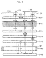
- Fig. 2 is an illustration for explaining a case in which the external light is incident on a display device using the polarized light splitter 160 (that is, a reflective display).
- this display device employs a TN liquid crystal 140 as polarization axis variable means.
- a polarizer 130 is provided as one example of first polarized light splitting means.
- a polarizer 135 is located as one example of second polarized light splitting means, a light scattering layer 150 is located as one example of a light diffusion means, and a polarized light splitter 160 is located as one example of third polarized light splitting means.
- a light guide 190 is placed as one example of a light guider for guiding light source light emitted from a light source 191 such as an LED so that it is incident on the polarized light splitter 160 from the underside, and a reflecting plate 200 is situated under the light guide 190.
- the natural light 121 turns through the polarizer 130 to linearly polarized light parallel with the paper surface, and then forms linearly polarized light in a direction perpendicular to the paper surface with its polarizing direction being twisted 90° by the TN liquid crystal 140, thereafter passing through the polarizer 135 as linearly polarized light in a direction perpendicular to the paper surface.
- This linearly polarized light is developed into white scattering light by means of the light scattering layer 150, and subsequently is evolved into linearly polarized light perpendicular to the paper surface by means of the polarized light splitter 160, thereafter penetrating the same polarized light splitter 160.
- the linearly polarized light passes through the transparent light guide 190 and, after being reflected on the reflecting plate 200, again passes through the light guide 190 and the polarized light splitter 160 as linearly polarized light in a direction perpendicular to the paper surface.
- This linearly polarized light is again evolved into white scattering light by the light scattering layer 150 and developed into linearly polarized light in a direction perpendicular to the paper surface by the polarizer 135, before passing through this polarizer 135.
- the light scattering layer 150 is provided between the polarizer 135 and the polarized light splitter 160, when the light 122 is viewed from the polarizer 130 side, it looks as if the scattering plane of the light diffusion layer 150 in which the reflected light is scattered forwardly is at the reflecting position. That is, because of the forward scattering in the light diffusion layer 150, little or no image nor shadow appears at the more rear side than the light diffusion layer 150. Accordingly, in the device structure, even if the distance from the TN liquid crystal 140 to the reflecting plate 200 is prolonged, no double image nor bleeding in display occurs due to the parallax resulting therefrom.
- such a light scattering layer 150 is also producible, for example, by mixing, into a polymeric resin, particulate of a resin different in refractive index from the polymeric resin. Additionally, this light scattering layer 150 can be formed to have a forward scattering characteristic, for example, at a haze value of approximately 15 to 95%, while the degree of the forward scattering characteristic depends experientially, experimentally and theoretically upon the device specification or the required image quality.
- the light reflected on the reflecting plate 200 includes, in addition to linearly polarized light in a direction perpendicular to the paper surface, linearly polarized light in a direction parallel with the paper surface.
- This linearly polarized light parallel with the paper surface is reflected on the polarized light splitter 160 and is again reflected by the reflecting plate 200 so that its polarizing direction varies, at least partially form linearly polarized light in a direction perpendicular to the paper surface.
- This linearly polarized light passes through the polarized light splitter 160. The repetition of this operation enables effective utilization of light for brightness. In this way, in the voltage non-application section, the light incident thereon can effectively be used owing to the polarized light splitter 160 to produce a bright display.
- the natural light 111 turns to linearly polarized light in a direction parallel with the paper surface by means of the polarizer 130, and subsequently passes through the TN liquid crystal 140 without changing its polarizing direction and is absorbed by the polarizer 135, thereby producing a dark state.
- the light reflected on the reflecting plate 200 is scattered forwardly by the light scattering layer 150 to be once developed into white scattering light, so it is possible to reduce the double image and bleeding in display and further to effectively utilize the light by the polarized light splitter 160, thereby offering a bright display.
- the voltage applied section 110 the light is absorbed by the polarizer 135 to produce a dark display so that high contrast is attainable.
- the device shown in Fig. 3 is identical to that shown in Fig. 2.
- the linearly polarized light in a direction perpendicular to the paper surface passes through the polarized light splitter 160. Additionally, of the light source light 125, the linearly polarized light in a direction parallel with the paper surface is reflected on the polarized light splitter 160 and again reflected on the reflecting plate 200 so that its polarizing direction varies, so that a portion thereof forms linearly polarized light in a direction perpendicular to the paper surface and passes through the polarized light splitter 160. When this operation is repeated, almost all the light passes through the polarized light splitter 160.
- the linearly polarized light passing through the polarized light splitter 160 and running in the direction perpendicular to the paper surface is evolved into white scattering light by the light scattering layer 150 and then developed by the polarizer 135 into linearly polarized light in a direction perpendicular to the paper surface to pass through the polarizer 135.
- This light undergoes a twist of its polarizing direction by 90° in the TN liquid crystal 140 to form linearly polarized light in a direction parallel with the paper surface, then passing through the polarizer 130. That is, it is possible to effectively use almost all the light, thus offering extreme brightness.
- the light source light 115 reaches the TN liquid crystal 140 and then turns to linearly polarized light in a direction perpendicular to the paper surface without a change of its polarizing direction by the TN liquid crystal 140, and subsequently is absorbed by the polarizer 130, thereby producing darkness.
- the transmissive display in the voltage non-applied section 120, it is possible to effectively use almost all the light owing to the polarized light splitter 160, thus offering extreme brightness.
- the polarizer 130 performs the absorption to produce darkness. Accordingly, in the state where the light source 190 comes on, a black display is attainable on the background of the light source color. That is, it is possible to gain a monochrome display without causing the positive-negative reversal between the transmissive display relying on the light source light and the reflective display (see Fig. 2) relying on the external light.
- the normally black mode is also acceptable.
- the normally white mode the brightness effect not only in the reflective display but also in the transmissive display is still exhibitable.
- the TN liquid crystal 140 has been used as an example, even if in place of the TN liquid crystal 140 there is employed another device such as a STN liquid crystal or an ECB (Electrically Controlled Birefringence) liquid crystal in which the polarization axis is changeable by voltages or the like, the basic operational principle is the same.
- a STN liquid crystal or an ECB (Electrically Controlled Birefringence) liquid crystal in which the polarization axis is changeable by voltages or the like, the basic operational principle is the same.
- Fig. 4 is an exploded cross-sectional view for explaining a display device according to a first embodiment of this invention.
- an STN cell 20 is put to use. Above the STN cell 20, a retardation film 14 and a polarizer 12 are provided in this order. Under the STN cell 20, a polarizer 15 and a polarized light splitter 40 are provided in this order. Additionally, there is placed a light source 70 whereby light can be incident on the polarized light splitter 40 from the underside. An LED (Light Emitting Diode) 71 is employed as the light source 70, and light therefrom is emitted upwardly through a light guide 72. Under the light guide 72, a diffusion plate 30 is provided as one example of light diffusion means and a reflecting plate 80 is set as one example of light reflecting means. In Fig. 4, for convenience in the description, the respective members are shown in a state spaced from each other, but in fact these members are disposed in a state adhered closely to each other.
- transparent materials for formation of the light guide 72 there are transparent resins such as an acrylic resin, a polycarbonate resin and an amorphous polyolefine resin, inorganic transparent materials such as a glass, and complexes thereof.
- the thickness is 0.3 to 2 mm.
- the size thereof is below approximately 300 ⁇ m.
- the size of the projections is approximately above 10 ⁇ m but below 100 ⁇ m.
- the ratio between the height of the projections and the width thereof (if it has a general cylindrical configuration, its diameter) can be less than 1 : 1.
- the configuration of the projections is a cylinder having a diameter of 20 ⁇ m and a height of 15 ⁇ m, and the pitch is 20 ⁇ m.
- the reflecting plate 80 is made in a manner that aluminum is deposited on a PET film or silver is deposited thereon, alternatively it can be an aluminum foil or the like. As the configuration of the surface of the reflecting plate 80, a mirror surface or a scattering surface is acceptable.
- an STN liquid crystal 26 is enclosed in a cell comprising two glass substrates 21 and 22 and a seal member 23.
- a transparent electrode 24 is put on a lower surface of the glass substrate 21 while a transparent electrode 25 is placed on an upper surface of the glass substrate 22.
- the transparent electrodes 24 and 25 it is possible to use an ITO (Indium Tin Oxide), a tin oxide or the like.
- the retardation film 14 is used as a color compensation optical anisotropy, and is used for correcting the coloring made in the STN cell 20.
- the polarized light splitter 40 in this embodiment the polarized light splitter described with reference to Fig. 1 is put to use.
- the external light becomes linearly polarized light in a predetermined direction due to the polarizer 12, and then its polarizing direction is twisted a predetermined angle by means of the STN cell 20.
- This linearly polarized light passes through the polarizer 15 and the polarized light splitter 40 and further passes through the light guide 72, thereafter being reflected on the reflecting plate 80.
- the reflected light again passes through the light guide 72, the polarized light splitter 40 and the polarizer 15 and reaches the STN cell 20 where its polarizing direction is twisted by a predetermined angle, finally emerging as linearly polarized light from the polarizer 12.
- the light whose polarizing direction is changed in the reflecting plate 80 is repeatedly reflected between the polarized light splitter 40 and the reflecting plate 80 and advances from the polarized light splitter 40 to the STN cell 20 in due course, thus producing a bright display. Since the diffusion plate 30 is provided between reflecting plate 80 and the polarized light splitter 40, the reflected light from the polarized light splitter 40 becomes white.
- the natural light becomes linearly polarized light in a predetermined direction by means of the polarizer 12, and then passes through the STN cell 20 as linearly polarized light and is absorbed by the polarizer 15, thus producing darkness.
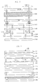
- Fig. 5 is a schematic illustration for explaining a liquid crystal display device according to a second embodiment of this invention.
- the second embodiment differs from the above-described first embodiment in that the diffusion 30 is positioned above the light guide 72.
- Other constructions are the same as those in the first embodiment.
- Fig. 5 the components similar to those in Fig. 4 are marked with the same reference numerals, and the description thereof will be omitted.
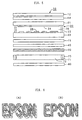
- Fig. 6 shows a display according to the first embodiment and a display according to the second embodiment, designated at (A) and (B), respectively, with both displaying "EPSON".
- a shadow appears dimly on the diffusion plate 30 due to the reflection on the reflecting plate 80.
- the shadow is seen dimly at a rear side corresponding to the thickness of the light guide 72, while in the second embodiment, the shadow does not lie deep, so the image is easier to see.
- the double image is shown remarkably. But in fact, since the diffusion plate 30 is provided between the STN cell 20 and the reflecting plate 80 as mentioned above in the first embodiment, although inferior to the second embodiment, also in the first embodiment the double image or bleeding is reducible in the reflective display.
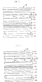
- Fig. 7 is a schematic illustration for explaining a liquid crystal display device according to a third embodiment of this invention.
- the third embodiment differs from the above-described embodiment in that the diffusion plate 30 is positioned above the polarized light splitter 40.
- Other constructions are the same as those in the first embodiment.
- components corresponding to those in Fig. 4 are marked with the same reference numerals, and the description thereof will be omitted.
- the distance between the diffusion plate 30 and the STN cell 20 is shortened, and double image, see Fig. 6, or bleeding in display is reducible accordingly.
- a fourth embodiment differs from the above-described third embodiment in that a pressure sensitive adhesive containing a diffusing agent is used as the diffusion plate 30.
- Other constructions are the same as those in the first embodiment.
- double image see Fig. 6, or bleeding in display is reducible.
- the polarizer 15 and the polarized light splitter 40, integrated with each other can be adhered to the STN cell 20, which is advantageous on manufacturing.
- Fig. 8 is a schematic illustration for explaining a liquid crystal display device according to a fifth embodiment of this invention.
- the difference of the fifth embodiment from the above-described first embodiment is that the diffusion plate 30 is positioned above the polarizer 15.
- Other constructions are the same as those in the first embodiment.
- components corresponding to those in Fig. 4 are marked with the same reference numerals, and the description thereof will be omitted.
- the distance between the diffusion plate 30 and the STN cell 20 is shortened, and the double image, see Fig. 6, or the bleeding is reducible accordingly.
- a sixth embodiment from the above-described fifth embodiment is that, in place of the polarized light splitter described with reference to Fig. 1, a combination of a circularly polarizer, constructed with a cholesteric liquid crystal or the like, and a ⁇ /4 plate is used as the polarized light splitter 40.
- Other constructions are the same as those in the first embodiment.
- the double image see Fig. 6, or the bleeding is reducible.
- Fig. 9 is an illustration for explaining a case in which the external light is incident on a color display device using the polarized light splitter shown in Fig. 1 (that is, a reflective display), while Fig. 10 is an illustration for describing a case in which a light source is turned on in this color display device (that is, a transmissive display).
- Figs. 9 and 10 components corresponding to those in Figs. 2 and 3 are marked with the same reference numerals, and they will be omitted from the description.
- this display device is equipped with a color filter 145 forming one example of coloring means and adjacent to the lower side of the TN liquid crystal 140.
- the natural light 121 turns to linearly polarized light in a direction parallel with the paper surface through the polarizer 130 and then forms linearly polarized light in a direction perpendicular to the paper surface with its polarizing direction being twisted 90° by the TN liquid crystal 140, and further passes through the color filter 145 and penetrates the polarizer 135 as linearly polarized light in a direction perpendicular to the paper surface.
- This linearly polarized light is evolved into white scattering light by the light scattering layer 150, and is developed into linearly polarized light in a direction perpendicular to the paper surface by the polarized light splitter 160, before passing through this polarized light splitter 160.
- this light passes through the transparent light guide 190 and is reflected on the reflecting plate 200 to again pass through the light guide 190 and the polarized light splitter 160 as linearly polarized light in a direction perpendicular to the paper surface.
- This linearly polarized light is again evolved into white scattering light by the light scattering layer 150 and then is developed into linearly polarized light in a direction perpendicular to the paper surface by the polarizer 135, before passing through this polarizer 135.
- the linearly polarized light becomes a linearly polarized light in a direction parallel with the paper surface with its polarizing direction being twisted 90° by the TN liquid crystal, and outputted from the polarizer 130 as linearly polarized light 122 in a direction parallel with the paper surface.
- the light scattering layer 150 is provided between the polarizer 135 and the polarized light splitter 160, when the light 122 is viewed from the polarizer 130 side, it seems that the scattering plane of the light diffusion layer 150 whereby the reflected light is scattered forwardly is at the reflecting position. That is, owing to the forward scattering in the light diffusion layer 150, images or shadows are hardly seen on the rear side of the light diffusion layer 150. Accordingly, even if, in the construction of the device, the distance from the TN liquid crystal 140 to the reflecting plate 200 is prolonged, double image or bleeding in display, caused by the parallax resulting therefrom, particularly bleeding of the colors produced by the color filter 145, does not occur.
- the light reflected on the reflecting plate 200 includes, in addition to the linearly polarized light in the direction perpendicular to the paper surface, linearly polarized light in a direction parallel with the paper surface.
- the linearly polarized light in the direction parallel with the paper surface is reflected on the polarized light splitter 160 and again reflected on the reflecting plate 200 so that its polarizing direction varies; whereupon, a portion of the linearly polarized light forms linearly polarized light in a direction perpendicular to the paper surface which in turn, passes through the polarized light splitter 160.
- the repetition of this operation enables effective utilization of light for brightness. In this way, in the voltage non-application section, the incident light can effectively be utilized owing to the polarized light splitter 160, thereby offering a bright display.
- the natural light 111 turns through the polarizer 130 to linearly polarized light in a direction parallel with the paper surface, and then passes through the TN liquid crystal 140 without a change of its polarizing direction, and is absorbed by the polarizer 135, thereby producing darkness.
- the light reflected on the reflecting plate 200 is scattered forwardly by the light scattering layer 150 to be evolved into white scattering light, so double image or bleeding in display, particularly bleeding of colors produced by the color filter 145, is reducible, and further the polarized light splitter 160 accomplishes effective utilization of light to produce a bright display.
- the voltage applied section 110 light is absorbed by the polarizer 135 to produce darkness, so high contrast is obtainable.
- the display device shown in Fig. 10 is identical to that shown in Fig. 9.
- light source light 115 reaches the TN liquid crystal 140 to form linearly polarized light in a direction perpendicular to the paper surface without a change of its polarizing direction, and is absorbed by the polarizer 130 into darkness.
- the polarized light splitter 160 permits effective utilization of light for extreme brightness, while in the voltage applied section 110, the light is absorbed by the polarizer 130 into darkness. Accordingly, at the lighting of the light source 190, a color display is obtainable on the background of the light source color. That is, a color display is feasible without positive-negative reversal in the transmissive display (see Fig. 3) relying on the light source light and in the reflective display (see Fig. 2) relying on the external light.
- the color pitch of the color filter 145 is, for example, as fine as approximately 80 ⁇ m
- the incident light and the outgoing light that is, reflected light
- an optical path includes, in addition to this optical path, one or a plurality of going and returning optical paths between the reflecting plate 200 and the polarized light splitter 160
- this pitch substantially pass through different color portions of the color filter 145.
- the light scattering layer 150 is interposed between the polarizer 135 and the polarized light splitter 160, even if the incident light passes through the color portions of the color filter 145 to be colored before being reflected, when passing through the light scattering layer 150, the light passing through the color portions of the color filter 145 is diffused forwardly, and further diffused forwardly in again passing through the light scattering layer 150 as the outgoing light reflected on the reflecting plate 200.
- the red, green and blue lights resulting from the passing of the incident light through the color filter 145 are mixed with each other to produce an optical condition almost identical to an optical condition in which, when viewed from the polarizer 130 side, white scattering light is emitted from the scattering plane of the light scattering layer 150 and is incident on the color filter 145 in this state.
- the color of the outgoing light becomes the color of the color filter 145 through which the outgoing light passes. Accordingly, even if the distance from the TN liquid crystal 140 to the reflecting plate 200 is prolonged in the device construction, the bleeding of the color produced through the color filter 145 does not occur, which is very advantageous.
- the color filter 145 shows a dot matrix display of red, green and blue, on this principle, multi-color and full-color display is feasible.
- the normally black is also acceptable.
- the normally white mode the brightness effect not only in the reflective display but also in the transmissive display is still exhibitable.
- the TN liquid crystal 140 has been used as an example, even if in place of the TN liquid crystal 140 there is employed another device such as a STN liquid crystal or an ECB (Electrically Controlled Birefringence) liquid crystal in which the polarization axis is changeable by voltages or the like, the basic operational principle is the same.
- a STN liquid crystal or an ECB (Electrically Controlled Birefringence) liquid crystal in which the polarization axis is changeable by voltages or the like, the basic operational principle is the same.
- Fig. 11 is a schematic illustration for explaining a liquid crystal display device according to a seventh embodiment of this invention.
- the seventh embodiment differs from the above-described first embodiment in that color filters 27 are provided in the interior of the STN cell 20.
- Other constructions are the same as those in the first embodiment.
- components corresponding to those in Fig. 4 are marked with the same reference numerals, and the description thereof will be omitted.
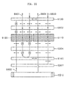
- the transparent electrode 24 is placed on a lower surface of the glass substrate 21 and transparent electrodes 25 are put on an upper surface of the glass substrate 22 to form a dot matrix, with red, green and blue color filters 27 being formed on a lower surface of the transparent electrode 24 to coincide with the electrode pattern of the transparent electrodes 25.
- the retardation film 14 is made to correct the coloring by the STN cell 20 for achromatic display.
- the direction of the polarization axis of the polarized light splitter 40 coincides with the direction of the polarization axis of the polarizer 15.
- the description begins at a reflective display using the external light.
- the natural light becomes linearly polarized light in a predetermined direction by means of the polarizer 12, and turns to linearly polarized light with its polarizing direction being twisted a predetermined angle by the STN cell 20, and further passes through the polarizer 15 and the polarized light splitter 40, and even passes through the light guide 72 to be reflected on the reflecting plate 80.
- the reflected light again passes through the light guide 72 and the polarized light splitter 40 and the polarizer 15 and is outputted as linearly polarized light from the polarizer 12 after it polarizing direction is twisted a predetermined angle.
- the light whose polarizing direction is changed by the reflecting plate 80 is repeatedly reflected between the polarized light splitter 40 and the reflecting plate 80, and eventually comes out of the polarized light splitter 40 and advances to the STN cell 20, thereby obtaining a bright display.
- the light passes through the color filter 27, one of the red, green and blue colors develops. Since the diffusion plate 30 is provided between the reflecting plate 80 and the polarized light splitter 40, the reflected light from the polarized light splitter 40 is scattered, thus providing a wide-visible-angle and good-looking display while suppressing the color bleeding.
- the natural light becomes linearly polarized light in a predetermined direction by means of the polarizer 12, and then passes through the STN cell 20 as the linearly polarized light, and further is absorbed by the polarizer 15, thereby producing darkness.
- the light emitted from the light source 70 becomes linearly polarized light through the polarized light splitter 40, before passing through it.
- This linearly polarized light becomes linearly polarized light in a predetermined direction by means of the STN cell 20, and is outputted without being absorbed by the polarizer 12.
- the color filter 27 one of the red, green and blue colors appears.
- the light emitted from the light source 70 becomes linearly polarized light by the polarized light splitter 40 and passes therethrough.
- This linearly polarized light turns to linearly polarized light in a predetermined direction through the STN cell 20, and is absorbed by the polarizer 12, thereby producing darkness.
- a color display is obtainable not only under the external light but also under the lighting of the light source without positive-negative reversal by the color filter 27.
- the diffusion plate 30 is placed between the STN cell 20 and the reflecting plate 80, even if the distance therebetween is long, double image or bleeding (particularly, color bleeding) is reducible in the reflective display.
- the polarized light splitter 40 enables the effective utilization of light, brightness is producible in both reflective and transmissive displays.
- the optical anisotropy in a plane of the light guide 72 chrominance non-uniformity occurs at a place having an anisotropy above 400 nm, whereas no chrominance non-uniformity occurs at a place having an anisotropy below 150 nm. Accordingly, it is preferable that the optical anisotropy in a plane of the light guide 72 is set to be below 400 nm, most preferably below 150 nm.
- Fig. 12 is a schematic illustration for explaining a liquid crystal display device according to an eighth embodiment of this invention.
- the difference of the eighth embodiment from the above-described seventh embodiment is that the diffusion plate 30 is positioned above the light guide 72.
- Other constructions are the same as those in the seventh embodiment.
- components corresponding to those in Fig. 11 are marked with the same reference numerals, and the description thereof will be omitted.
- a display according to the seventh embodiment and a display according to the eighth embodiment are shown at (A) and (B) in Fig. 6, respectively, as in the case of the display according to the first embodiment and the display according to the second embodiment. That is, in the seventh embodiment, a shadow clearly appears on the rear side corresponding to the thickness of the light guide 72, whereas in the eighth embodiment, the shadow becomes dim so that the display is easy to see.
- a color filter 24 of red, green and blue, different in transmittance ratio is provided.
- the average transmittance ratio of the color filter 24 is changed variously, if the average transmittance ratio exceeds 80%, the color purity drops so that the color recognition decreases. On the other hand, if the average transmittance ratio becomes below 30%, the brightness in the reflective display decreases so that the display is hard to read. Accordingly, preferably the average transmittance ratio of the color filter 24 is in a range of 30 to 80%, more preferably in a range of 45 to 70%.
- Figs. 13(a) and (b) The spectral characteristics of two kinds of color filters A and B different in average transmittance ratio from each other in the ninth embodiment are shown in Figs. 13(a) and (b), respectively.
- the average transmittance ratio of the color filter A is 58.1% while the average transmittance ratio of the color filter B is 67.7%.
- Fig. 14 in the form of a table, shows transmittance ratios and chromaticities of red, green and blue in the color filters A and B.
- Fig. 15 is a schematic illustration for explaining a liquid crystal display device according to a tenth embodiment of this invention.
- the difference of the tenth embodiment from the above-described seventh embodiment is that the diffusion plate 30 is positioned above the polarized light splitter 40.
- Other constructions are the same as those in the seventh embodiment.
- components corresponding to those in Fig. 11 are marked with the same reference numerals, and the description thereof will be omitted.
- the distance between the diffusion plate 30 and the STN cell 20 is shortened, so the double image, shown in Fig. 6, and bleeding in display is reducible accordingly.
- a difference of an eleventh embodiment from the above-described tenth embodiment is that a pressure sensitive adhesive containing a diffusing agent is used as the diffusion plate 30.
- Other constructions are the same as those in the tenth embodiment.
- the double image, shown in Fig. 6, and bleeding in display is reducible.
- the polarizer 15 and the polarized light splitter 40 in Fig. 15 are integrally adhered onto the STN cell 20, which is advantageous in manufacturing.
- Fig. 16 is a schematic illustration for explaining a liquid crystal display device according to a twelfth embodiment of this invention.
- the twelfth embodiment differs from the above-described seventh embodiment in that the diffusion plate 30 is positioned above the polarizer 15.
- Other constructions are the same as those in the seventh embodiment.
- parts corresponding to those in Fig. 11 are marked with the same reference numerals, and the description thereof will be omitted.
- the distance between the diffusion plate 30 and the STN cell 20 is shortened, so the double image, shown in Fig. 6, or bleeding in display is reducible accordingly.
- a thirteenth embodiment from the above-described tenth embodiment is that, in place of the polarized light splitter described with reference to Fig. 1, a combination of a circularly polarizer, constructed with a cholesteric liquid crystal or the like, and a ⁇ /4 plate is used as the polarized light splitter 40.
- Other constructions are the same as those in the tenth embodiment.
- the double image see Fig. 6, or the bleeding is reducible.
- Fig. 17 is a schematic illustration for explaining a liquid crystal display device according to a fourteenth embodiment of this invention.
- the fourteenth embodiment differs from the above-described twelfth embodiment in that a Lumisty85 produced by Sumitomo Chemical Co., Ltd. is placed on an upper surface of the reflecting plate 80.
- Other constructions are the same as those in the twelfth embodiment.
- parts corresponding to those in Fig. 16 are marked with the same reference numerals, and the description thereof will be omitted.
- the "Sumitomo Chemical Produced Lumisty85" exhibits an effect to make the output angle ⁇ 2 of light differ from the incidence angle ⁇ 1 as shown in Fig. 18 when combined with the reflecting plate 80. That is, when incident light 801 is incident on the Lumisty85 at the incidence angle ⁇ 1, the light 801 is outputted as diffused light. At this time, the output angle in the direction 802 having the highest intensity is taken as ⁇ 2. Thus, the incidence angle ⁇ 1 and the output angle ⁇ 2 differ from each other. This is because the Lumisty has the following structure and characteristic.
- the Lumisty layers different in refractive index from each other are arranged at an interval of approximately 3 ⁇ m in a film, and this construction causes a diffraction phenomenon to produce diffusion of light.
- the directional control of the diffused light is possible through the adjustment of the layer construction.
- the incidence angle is 70°
- the output angle is 90°. In this way, when a screen is viewed from the vertical direction, the screen is bright and easy to see without being dark due to the shadow of the observer. Additionally, the contrast also upgrades.
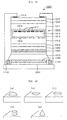
- a liquid crystal cell 1010 having an STN liquid crystal is used as one example of polarization axis variable means.
- a retardation film 1030 and an upper polarizer 1020 forming one example of a first polarized light splitter are located in this order.
- a lower polarizer 1040 forming one example of a second polarized light splitter, a pressure sensitive adhesive 1050 containing a light diffusing agent, forming one example of light diffusing means, a polarized light splitter 1060 forming a third polarized light splitting means, a light guide plate 1070 constituting a portion of the light guider and a reflecting plate 1080 forming one example of light reflecting means are provided in this order.
- the pressure sensitive adhesive 1040 containing light diffusing agent has both functions: a light diffusion effect and an adhesion effect, and the lower polarizer 1040 and the polarized light splitter 1060 are adhered. Additionally, a pressure sensitive adhesive also lies on an upper surface of the lower polarizer 1040, and it can be adhered to the liquid crystal cell 10.
- an STN liquid crystal 1014 is enclosed in a cell comprising two glass substrates 1011 and 1012 and a seal member 1013.
- the product ⁇ n ⁇ ⁇ d of the optical anisotropy ⁇ n of the STN liquid crystal 1014 in the liquid crystal cell 1010 and the thickness d of the liquid crystal layer is set at, for example, 860 nm.
- Transparent electrode lines 1015 and 1016 are formed inside the two glass substrates 1011 and 1012, respectively. Additionally, to the transparent electrode lines 1016 of the lower glass substrate 1012, red, green and blue color filters 1017 are located on the transparent electrode line 1015 of the upper glass substrate 1011. The use of the retardation film 1030 is for accomplishing the color compensation.
- An LED 1120 forming one example of a light source is located on a PCB substrate 1090 so that light is emitted upwardly from the LED 1120.
- a light guide 1110 forming one example of the light guider is provided on the PCB substrate 1090.
- the left and right positions of the liquid crystal cell 1010 and others are determined by the light guide 1110, and a structure comprising the liquid crystal cell 1010 and others is fixed thereby.
- the light guide 1110 extends upwardly, and the light guide plate 1070 is put in an intermediate portion thereof so that the light introduced from the LED 1120 into the light guide 1110 is further introduced into the light guide plate 1070.
- an upper end portion of the light guide 1110 is bent toward the inside of the upper polarizer 1020.
- the lower side of the upper end portion of the light guide 1110 and the upper polarizer 1020 are fixed to each other through a double-faced adhesive tape 1112.
- the light guide 1110 can also be a cavity surrounded by a transparent plastic plate or the like, alternatively by an opaque plastic plate having a reflecting function.
- Light from the LED 1120 is guided through the light guide 1110 to be introduced into the interior of the liquid guide plate 1070 and then outputted toward the polarized light splitter 1060 side.
- the light guide plate 1070 transmits the light from the liquid crystal cell 1010 side to the reflecting plate 1080.
- the polarized light splitter 1060 has a structure similar to that shown in Fig. 1.
- a pressure sensitive adhesive is placed on an upper surface of the reflecting plate 1080 which in turn, is adhered to the light guide plate 1070.
- the light guide plate 1070 is made so as not to have a large projection in its thickness direction. Accordingly, the light guide plate 1070 is made from a transparent plastic flat-plate having a thickness of approximately 0.7 mm.
- liquid crystal cell 1010 When the liquid crystal cell 1010 is frame-rate-controlled, a bright full-color display is attainable not only when the external light is used and but also when the LED is in the on condition.
- the color filters 1017 can provide a color display without positive-negative reversal not only under the external light but also under the lighting of the light source. Additionally, since the pressure sensitive adhesive 1050 containing light diffusing agent is interposed between the liquid crystal cell 1010 and the reflecting plate 1090, if the distance therebetween is prolonged, the double image or the bleeding (particularly, color bleeding) is reducible in the reflective display. Still additionally, since the effective utilization of light is feasible through the use of the polarized light splitter 1060, both the reflective and transmissive displays becomes bright.
- a sixteenth embodiment according to this invention relates to a light guide 72 suitable for use in the above-described display devices according to the first to fourteenth embodiments.
- the light guide 72 used in the display devices according to the first to fourteenth embodiments of this invention is made from a transparent plastic plate, such as polycarbonate or acrylic, and has a thickness of 0.3 to 2 mm, and further has irregularities on its surface.
- the size thereof is in a range of approximately 10 to 200 ⁇ m and the pitch thereof is in a range of approximately 20 to 400 ⁇ m.
- the configuration thereof is, for example, a generally hemispherical projection as shown in Fig. 20(a), a conical recess as shown in Fig. 20(b), a generally hemispherical recess as shown in Fig. 20(c), a cylindrical projection as shown in Fig.
- the light guide 72 also serves as a diffusion plate.
- the light guide 72 is produced with the injection molding, and in order to lessen the optical anisotropy, undergoes heating or pressuring treatment.
- a seventh embodiment relates to an electronic apparatus incorporating the monochrome or color liquid crystal display device according to each of the above-described embodiments.
- liquid crystal display device when used, for example, for a display section 172 of a portable telephone 171 shown in Fig. 21(a), it is possible to realize an energy-saving portable telephone providing a bright high-contrast reflective or transmissive display even in the daylight, in the shade or in room.
- a display section 174 of a wristwatch 173 shown in Fig. 21(b) it is possible to realize an energy-saving wristwatch providing a bright high-contrast reflective or transmissive display even in the daylight, in the shade or in a room.
- a display screen 176 attached to a mainframe 177 of a personal computer (or an information terminal) 175 shown in Fig. 21(c) it is possible to realize an energy-saving personal computer providing a bright high-contrast reflective or transmissive display even in the daylight, in the shade or in room.
- liquid crystal display devices are also applicable to electronic apparatuses, such as a liquid crystal television, a viewfinder or monitor direct-viewing video tape recorder, a car navigation apparatus, an electronic pocketbook, a desk computer, a word processor, an engineering work station (EWS), a television telephone, a POS terminal and an apparatus equipped with a touch panel.
- electronic apparatuses such as a liquid crystal television, a viewfinder or monitor direct-viewing video tape recorder, a car navigation apparatus, an electronic pocketbook, a desk computer, a word processor, an engineering work station (EWS), a television telephone, a POS terminal and an apparatus equipped with a touch panel.
- EWS engineering work station
- the display devices, the electronic apparatus and the light guider according to this invention are not limited to the above-described embodiments, but it should be understood that that they are intended to cover all changes of the embodiments of the invention herein used for the purpose of the disclosure, which do not constitute departures from the point and spirit of the invention readable from the claims and the entire description, and the technical scope of this invention also includes a display device, an electronic apparatus and a light guider involving the changes.
- the display devices according to this invention are available as various types of display devices capable of providing a bright good-looking monochrome or color display, and further they are available as display devices constituting display sections of various types of electronic apparatus. Furthermore, the electronic apparatus according to this invention is applicable to a liquid crystal television, a viewfinder or monitor direct-viewing video tape recorder, a car navigation apparatus, an electronic pocketbook, an electronic calculator , a word processor, a work station, a portable telephone, a television telephone, a POS terminal, a touch panel and others, using such a display device.
Landscapes
- Physics & Mathematics (AREA)
- Nonlinear Science (AREA)
- Mathematical Physics (AREA)
- Chemical & Material Sciences (AREA)
- Crystallography & Structural Chemistry (AREA)
- General Physics & Mathematics (AREA)
- Optics & Photonics (AREA)
- Liquid Crystal (AREA)
Applications Claiming Priority (5)
| Application Number | Priority Date | Filing Date | Title |
|---|---|---|---|
| JP2371999 | 1999-02-01 | ||
| JP2371999 | 1999-02-01 | ||
| JP15989999 | 1999-06-07 | ||
| JP15989999 | 1999-06-07 | ||
| PCT/JP2000/000367 WO2000046633A1 (fr) | 1999-02-01 | 2000-01-25 | Dispositif d'affichage, dispositif electronique et guide lumineux |
Publications (3)
| Publication Number | Publication Date |
|---|---|
| EP1067424A1 true EP1067424A1 (fr) | 2001-01-10 |
| EP1067424A4 EP1067424A4 (fr) | 2003-09-10 |
| EP1067424B1 EP1067424B1 (fr) | 2009-01-07 |
Family
ID=26361128
Family Applications (1)
| Application Number | Title | Priority Date | Filing Date |
|---|---|---|---|
| EP00900929A Expired - Lifetime EP1067424B1 (fr) | 1999-02-01 | 2000-01-25 | Dispositif d'affichage, dispositif electronique et guide lumineux |
Country Status (8)
| Country | Link |
|---|---|
| US (2) | US6630968B1 (fr) |
| EP (1) | EP1067424B1 (fr) |
| JP (1) | JP3674510B2 (fr) |
| KR (1) | KR100433607B1 (fr) |
| CN (1) | CN1156731C (fr) |
| DE (1) | DE60041303D1 (fr) |
| TW (1) | TWI274204B (fr) |
| WO (1) | WO2000046633A1 (fr) |
Cited By (1)
| Publication number | Priority date | Publication date | Assignee | Title |
|---|---|---|---|---|
| WO2004111352A1 (fr) * | 2003-06-18 | 2004-12-23 | Derrick Anthony Rhodes | Portique utilitaire |
Families Citing this family (49)
| Publication number | Priority date | Publication date | Assignee | Title |
|---|---|---|---|---|
| KR20010094773A (ko) * | 2001-03-16 | 2001-11-03 | 장광식 정윤철 | 편광판 일체형 터치 패널 및 터치 패널 일체형 평판디스플레이 그리고 적층 방법 |
| TW557371B (en) | 2001-07-02 | 2003-10-11 | Sumitomo Chemical Co | Semi-transparent-semi-reflectivity film, semi- transparent-semi-reflectivity polarized film, polarized light device using these films, and liquid crystal display device using these films |
| JP2003029251A (ja) * | 2001-07-16 | 2003-01-29 | Nec Corp | 液晶表示装置 |
| US7301591B2 (en) * | 2001-09-28 | 2007-11-27 | Citizen Holdings Co., Ltd. | Liquid crystal display device wherein the number of light emitting elements activated differs depending on whether display is performed by the first or second liquid crystal panel |
| US7072096B2 (en) * | 2001-12-14 | 2006-07-04 | Digital Optics International, Corporation | Uniform illumination system |
| JP2003279987A (ja) * | 2002-03-26 | 2003-10-02 | Seiko Epson Corp | 液晶表示装置および電子機器 |
| JP2003279986A (ja) * | 2002-03-26 | 2003-10-02 | Seiko Epson Corp | 液晶表示装置および電子機器 |
| JP2004199027A (ja) * | 2002-10-24 | 2004-07-15 | Seiko Epson Corp | 表示装置、及び電子機器 |
| JP4574942B2 (ja) * | 2002-10-28 | 2010-11-04 | 株式会社 日立ディスプレイズ | 液晶表示装置 |
| TWI289708B (en) | 2002-12-25 | 2007-11-11 | Qualcomm Mems Technologies Inc | Optical interference type color display |
| JP4994567B2 (ja) * | 2003-10-20 | 2012-08-08 | 日東電工株式会社 | 直線偏光分離フィルム、直線偏光分離積層フィルム、バックライトシステム、液晶表示装置 |
| US7342705B2 (en) | 2004-02-03 | 2008-03-11 | Idc, Llc | Spatial light modulator with integrated optical compensation structure |
| US7710632B2 (en) * | 2004-09-27 | 2010-05-04 | Qualcomm Mems Technologies, Inc. | Display device having an array of spatial light modulators with integrated color filters |
| US7630123B2 (en) | 2004-09-27 | 2009-12-08 | Qualcomm Mems Technologies, Inc. | Method and device for compensating for color shift as a function of angle of view |
| US8362987B2 (en) | 2004-09-27 | 2013-01-29 | Qualcomm Mems Technologies, Inc. | Method and device for manipulating color in a display |
| US7161651B2 (en) * | 2004-11-20 | 2007-01-09 | Luxell Technologies Inc. | Method of resizing a liquid crystal display |
| US7466309B2 (en) * | 2004-12-03 | 2008-12-16 | Hewlett-Packard Development Company, L.P. | Display system and method using a projector and a reflective display |
| US7210809B2 (en) * | 2005-04-08 | 2007-05-01 | Robert Blackstock | Decorative optical display |
| JP4579146B2 (ja) | 2005-12-06 | 2010-11-10 | 株式会社 日立ディスプレイズ | 表示装置および面状光源装置 |
| CN100443979C (zh) * | 2006-01-18 | 2008-12-17 | 友达光电股份有限公司 | 平面显示模块 |
| CN101401497B (zh) * | 2006-02-10 | 2013-01-02 | 诺基亚公司 | 显示模块和固定的方法 |
| US20070236628A1 (en) * | 2006-03-31 | 2007-10-11 | 3M Innovative Properties Company | Illumination Light Unit and Optical System Using Same |
| CN101443698B (zh) * | 2006-05-11 | 2011-02-09 | 夏普株式会社 | 液晶显示装置 |
| EP2069838A2 (fr) | 2006-10-06 | 2009-06-17 | Qualcomm Mems Technologies, Inc. | Dispositif d'éclairage intégrant un coupleur de lumière |
| ATE556272T1 (de) | 2006-10-06 | 2012-05-15 | Qualcomm Mems Technologies Inc | Optische verluststruktur in einer beleuchtungsvorrichtung |
| EP1943551A2 (fr) | 2006-10-06 | 2008-07-16 | Qualcomm Mems Technologies, Inc. | Guide de lumière |
| WO2008045463A2 (fr) | 2006-10-10 | 2008-04-17 | Qualcomm Mems Technologies, Inc. | Dispositif d'affichage à optique de diffraction |
| US20080304801A1 (en) * | 2007-06-11 | 2008-12-11 | Jeng Shiang Precision Ind. Co., Ltd. | High-brightness light guide plate |
| US8068710B2 (en) | 2007-12-07 | 2011-11-29 | Qualcomm Mems Technologies, Inc. | Decoupled holographic film and diffuser |
| WO2009079279A2 (fr) | 2007-12-17 | 2009-06-25 | Qualcomm Mems Technologies, Inc. | Dispositifs photovoltaïques ayant des masques interférométriques sur le côté arrière |
| JP2009157276A (ja) * | 2007-12-27 | 2009-07-16 | Casio Comput Co Ltd | 液晶表示装置 |
| US8721149B2 (en) | 2008-01-30 | 2014-05-13 | Qualcomm Mems Technologies, Inc. | Illumination device having a tapered light guide |
| EP2247978A4 (fr) | 2008-01-30 | 2012-12-26 | Qualcomm Mems Technologies Inc | Système d éclairage mince |
| US8654061B2 (en) | 2008-02-12 | 2014-02-18 | Qualcomm Mems Technologies, Inc. | Integrated front light solution |
| KR101542915B1 (ko) | 2008-10-10 | 2015-08-07 | 퀄컴 엠이엠에스 테크놀로지스, 인크. | 분산 조명 시스템 |
| JP4900363B2 (ja) * | 2008-10-28 | 2012-03-21 | カシオ計算機株式会社 | 液晶表示装置 |
| JP4905438B2 (ja) * | 2008-11-18 | 2012-03-28 | カシオ計算機株式会社 | 液晶表示装置 |
| CN102272516A (zh) | 2009-01-13 | 2011-12-07 | 高通Mems科技公司 | 大面积光面板及屏幕 |
| CA2750163A1 (fr) * | 2009-01-23 | 2010-07-29 | Manish Kothari | Dispositif integre d'emission de lumiere et de detection de lumiere |
| JP5163571B2 (ja) * | 2009-03-23 | 2013-03-13 | カシオ計算機株式会社 | 液晶表示装置 |
| WO2010138761A1 (fr) | 2009-05-29 | 2010-12-02 | Qualcomm Mems Technologies, Inc. | Dispositifs d'éclairage et leurs procédés de fabrication |
| US8848294B2 (en) | 2010-05-20 | 2014-09-30 | Qualcomm Mems Technologies, Inc. | Method and structure capable of changing color saturation |
| US8402647B2 (en) | 2010-08-25 | 2013-03-26 | Qualcomm Mems Technologies Inc. | Methods of manufacturing illumination systems |
| US8902484B2 (en) | 2010-12-15 | 2014-12-02 | Qualcomm Mems Technologies, Inc. | Holographic brightness enhancement film |
| JP5426588B2 (ja) * | 2011-02-07 | 2014-02-26 | 株式会社ジャパンディスプレイ | 液晶表示装置 |
| JP5710302B2 (ja) | 2011-02-09 | 2015-04-30 | 株式会社ジャパンディスプレイ | 液晶表示装置 |
| CN103869533B (zh) * | 2014-03-25 | 2017-01-04 | 汕头超声显示器技术有限公司 | 一种改善底色的液晶显示器 |
| CN108595050B (zh) * | 2018-04-25 | 2021-01-26 | 京东方科技集团股份有限公司 | 触控显示装置及其驱动方法 |
| TWM576667U (zh) * | 2018-10-22 | 2019-04-11 | 隆達電子股份有限公司 | 顯示裝置 |
Family Cites Families (29)
| Publication number | Priority date | Publication date | Assignee | Title |
|---|---|---|---|---|
| JPH0196922A (ja) * | 1987-10-08 | 1989-04-14 | Mitsubishi Rayon Co Ltd | 半導体製造装置 |
| USRE37377E1 (en) * | 1992-10-09 | 2001-09-18 | Asahi Glass Company, Ltd. | LCD device including an illumination device having a polarized light separating sheet between a light guide and the display |
| US5988826A (en) * | 1993-03-25 | 1999-11-23 | Enplas Corporation | Surface light source device |
| JPH0736025A (ja) * | 1993-07-23 | 1995-02-07 | Fuji Xerox Co Ltd | バックライト光源 |
| CN1052795C (zh) | 1993-12-21 | 2000-05-24 | 美国3M公司 | 光学显示器 |
| US5686979A (en) | 1995-06-26 | 1997-11-11 | Minnesota Mining And Manufacturing Company | Optical panel capable of switching between reflective and transmissive states |
| JPH09258203A (ja) | 1996-03-19 | 1997-10-03 | Hitachi Ltd | 液晶表示装置 |
| GB2306741A (en) * | 1995-10-24 | 1997-05-07 | Sharp Kk | Illuminator |
| US6104454A (en) * | 1995-11-22 | 2000-08-15 | Hitachi, Ltd | Liquid crystal display |
| JP3479977B2 (ja) * | 1996-09-17 | 2003-12-15 | セイコーエプソン株式会社 | 表示装置及びそれを用いた電子機器 |
| JPH1096922A (ja) * | 1996-09-25 | 1998-04-14 | Hitachi Ltd | 液晶表示装置 |
| US6390626B2 (en) * | 1996-10-17 | 2002-05-21 | Duke University | Image projection system engine assembly |
| US5972457A (en) * | 1996-12-03 | 1999-10-26 | Mitsubishi Chemical Corporation | Optical recording medium |
| WO1998032046A1 (fr) * | 1997-01-17 | 1998-07-23 | Seiko Epson Corporation | Dispositif a cristaux liquides et appareil electronique pourvu de ce dispositif |
| JPH10260403A (ja) * | 1997-01-20 | 1998-09-29 | Seiko Epson Corp | 液晶装置及び電子機器 |
| JPH10293212A (ja) * | 1997-02-18 | 1998-11-04 | Dainippon Printing Co Ltd | バックライト及び液晶表示装置 |
| JP4076028B2 (ja) * | 1997-02-18 | 2008-04-16 | 大日本印刷株式会社 | 偏光分離フィルム、バックライト及び液晶表示装置 |
| JPH10253830A (ja) * | 1997-03-07 | 1998-09-25 | Fujitsu Kasei Kk | バックライトユニット |
| CN1140835C (zh) * | 1997-05-07 | 2004-03-03 | 精工爱普生株式会社 | 显示元件和电子表 |
| JP3539206B2 (ja) * | 1997-06-09 | 2004-07-07 | セイコーエプソン株式会社 | 電子時計および液晶表示素子 |
| JP3702643B2 (ja) * | 1997-06-09 | 2005-10-05 | セイコーエプソン株式会社 | 表示装置及び電子時計 |
| JPH1164841A (ja) | 1997-08-19 | 1999-03-05 | Hitachi Ltd | 液晶表示装置 |
| JPH1164840A (ja) | 1997-08-19 | 1999-03-05 | Hitachi Ltd | 液晶表示装置 |
| JPH1172782A (ja) | 1997-08-27 | 1999-03-16 | Citizen Watch Co Ltd | 液晶表示装置 |
| JP3460588B2 (ja) * | 1997-09-18 | 2003-10-27 | セイコーエプソン株式会社 | 表示装置及びそれを用いた電子機器 |
| JPH11167110A (ja) * | 1997-12-02 | 1999-06-22 | Denso Corp | 液晶表示装置 |
| JP3520494B2 (ja) * | 1998-05-11 | 2004-04-19 | 日東電工株式会社 | 反射型液晶表示装置 |
| US6243068B1 (en) * | 1998-05-29 | 2001-06-05 | Silicon Graphics, Inc. | Liquid crystal flat panel display with enhanced backlight brightness and specially selected light sources |
| US6208466B1 (en) * | 1998-11-25 | 2001-03-27 | 3M Innovative Properties Company | Multilayer reflector with selective transmission |
-
2000
- 2000-01-25 DE DE60041303T patent/DE60041303D1/de not_active Expired - Lifetime
- 2000-01-25 KR KR10-2000-7010873A patent/KR100433607B1/ko not_active Expired - Lifetime
- 2000-01-25 EP EP00900929A patent/EP1067424B1/fr not_active Expired - Lifetime
- 2000-01-25 CN CNB008000972A patent/CN1156731C/zh not_active Expired - Lifetime
- 2000-01-25 JP JP2000597654A patent/JP3674510B2/ja not_active Expired - Lifetime
- 2000-01-25 WO PCT/JP2000/000367 patent/WO2000046633A1/fr not_active Ceased
- 2000-01-25 US US09/647,394 patent/US6630968B1/en not_active Expired - Lifetime
- 2000-01-25 TW TW089101221A patent/TWI274204B/zh not_active IP Right Cessation
-
2002
- 2002-12-09 US US10/315,508 patent/US20030081151A1/en not_active Abandoned
Cited By (1)
| Publication number | Priority date | Publication date | Assignee | Title |
|---|---|---|---|---|
| WO2004111352A1 (fr) * | 2003-06-18 | 2004-12-23 | Derrick Anthony Rhodes | Portique utilitaire |
Also Published As
| Publication number | Publication date |
|---|---|
| CN1293768A (zh) | 2001-05-02 |
| WO2000046633A1 (fr) | 2000-08-10 |
| US6630968B1 (en) | 2003-10-07 |
| CN1156731C (zh) | 2004-07-07 |
| JP3674510B2 (ja) | 2005-07-20 |
| EP1067424B1 (fr) | 2009-01-07 |
| TWI274204B (en) | 2007-02-21 |
| KR20010042323A (ko) | 2001-05-25 |
| US20030081151A1 (en) | 2003-05-01 |
| EP1067424A4 (fr) | 2003-09-10 |
| KR100433607B1 (ko) | 2004-05-31 |
| DE60041303D1 (de) | 2009-02-26 |
Similar Documents
| Publication | Publication Date | Title |
|---|---|---|
| US6630968B1 (en) | Display device, electronic apparatus using the same, and light guider for display devices | |
| JP3820595B2 (ja) | 表示装置及びそれを用いた電子機器並びに偏光分離器 | |
| JP3337028B2 (ja) | 液晶装置及び電子機器 | |
| EP0877282B1 (fr) | Dispositif d'affichage à cristal liquide | |
| JP3073025B2 (ja) | 液晶表示装置 | |
| US6400432B2 (en) | Liquid crystal device and electronic apparatus using the same | |
| US6344887B1 (en) | Full spectrum reflective choleterics display employing circular polarizers with the same polarity but different disposition | |
| EP0913721B1 (fr) | Affichage et dispositif electronique comprenant cet affichage | |
| JPWO2000046633A1 (ja) | 表示装置、それを用いた電子機器及び表示装置用の導光体 | |
| KR100505522B1 (ko) | 표시 장치 및 그것을 이용한 전자 기기 | |
| JPWO1999004315A1 (ja) | 液晶表示装置 | |
| US6067136A (en) | Birefringence-type color liquid crystal display device | |
| JPWO1999006880A1 (ja) | 液晶表示装置 | |
| JP2001083509A (ja) | 液晶表示装置およびそれを用いた電子機器 | |
| US8040475B2 (en) | Reflective morphable display device and method of feature activation | |
| JP3345772B2 (ja) | 液晶装置及び電子機器 | |
| JP3584471B2 (ja) | 表示装置及び電子機器 | |
| JP3350022B2 (ja) | 液晶表示装置 | |
| JPH11142646A (ja) | 反射偏光子、液晶装置及び電子機器 | |
| JP3337029B2 (ja) | 液晶装置及び電子機器 | |
| JP3271264B2 (ja) | 表示装置及びそれを用いた電子機器 | |
| JP3389924B2 (ja) | 液晶装置及び電子機器 | |
| JP2000066189A (ja) | 液晶表示装置及びそれを用いた電子機器 | |
| TWI244568B (en) | Liquid crystal display (LCD) panel with dual-display mode | |
| JP2004138633A (ja) | 表示装置及び電子機器 |
Legal Events
| Date | Code | Title | Description |
|---|---|---|---|
| PUAI | Public reference made under article 153(3) epc to a published international application that has entered the european phase |
Free format text: ORIGINAL CODE: 0009012 |
|
| AK | Designated contracting states |
Kind code of ref document: A1 Designated state(s): DE FR GB |
|
| 17P | Request for examination filed |
Effective date: 20010108 |
|
| A4 | Supplementary search report drawn up and despatched |
Effective date: 20030724 |
|
| 16A | New documents despatched to applicant after publication of the search report |
Effective date: 20040408 |
|
| RA4 | Supplementary search report drawn up and despatched (corrected) |
Effective date: 20040408 |
|
| 17Q | First examination report despatched |
Effective date: 20050509 |
|
| 17Q | First examination report despatched |
Effective date: 20050509 |
|
| GRAP | Despatch of communication of intention to grant a patent |
Free format text: ORIGINAL CODE: EPIDOSNIGR1 |
|
| GRAS | Grant fee paid |
Free format text: ORIGINAL CODE: EPIDOSNIGR3 |
|
| GRAA | (expected) grant |
Free format text: ORIGINAL CODE: 0009210 |
|
| AK | Designated contracting states |
Kind code of ref document: B1 Designated state(s): DE FR GB |
|
| REG | Reference to a national code |
Ref country code: GB Ref legal event code: FG4D |
|
| REF | Corresponds to: |
Ref document number: 60041303 Country of ref document: DE Date of ref document: 20090226 Kind code of ref document: P |
|
| PLBE | No opposition filed within time limit |
Free format text: ORIGINAL CODE: 0009261 |
|
| STAA | Information on the status of an ep patent application or granted ep patent |
Free format text: STATUS: NO OPPOSITION FILED WITHIN TIME LIMIT |
|
| 26N | No opposition filed |
Effective date: 20091008 |
|
| PGFP | Annual fee paid to national office [announced via postgrant information from national office to epo] |
Ref country code: FR Payment date: 20120202 Year of fee payment: 13 |
|
| PGFP | Annual fee paid to national office [announced via postgrant information from national office to epo] |
Ref country code: DE Payment date: 20120118 Year of fee payment: 13 |
|
| PGFP | Annual fee paid to national office [announced via postgrant information from national office to epo] |
Ref country code: GB Payment date: 20120125 Year of fee payment: 13 |
|
| GBPC | Gb: european patent ceased through non-payment of renewal fee |
Effective date: 20130125 |
|
| REG | Reference to a national code |
Ref country code: FR Ref legal event code: ST Effective date: 20130930 |
|
| PG25 | Lapsed in a contracting state [announced via postgrant information from national office to epo] |
Ref country code: DE Free format text: LAPSE BECAUSE OF NON-PAYMENT OF DUE FEES Effective date: 20130801 |
|
| REG | Reference to a national code |
Ref country code: DE Ref legal event code: R119 Ref document number: 60041303 Country of ref document: DE Effective date: 20130801 |
|
| PG25 | Lapsed in a contracting state [announced via postgrant information from national office to epo] |
Ref country code: GB Free format text: LAPSE BECAUSE OF NON-PAYMENT OF DUE FEES Effective date: 20130125 Ref country code: FR Free format text: LAPSE BECAUSE OF NON-PAYMENT OF DUE FEES Effective date: 20130131 |