EP1067448B1 - Système-PC pour programmes en temps réel et temps non réel - Google Patents
Système-PC pour programmes en temps réel et temps non réel Download PDFInfo
- Publication number
- EP1067448B1 EP1067448B1 EP00113794A EP00113794A EP1067448B1 EP 1067448 B1 EP1067448 B1 EP 1067448B1 EP 00113794 A EP00113794 A EP 00113794A EP 00113794 A EP00113794 A EP 00113794A EP 1067448 B1 EP1067448 B1 EP 1067448B1
- Authority
- EP
- European Patent Office
- Prior art keywords
- clock
- real
- time
- communication
- counter
- Prior art date
- Legal status (The legal status is an assumption and is not a legal conclusion. Google has not performed a legal analysis and makes no representation as to the accuracy of the status listed.)
- Expired - Lifetime
Links
Images

Classifications
-
- G—PHYSICS
- G06—COMPUTING OR CALCULATING; COUNTING
- G06F—ELECTRIC DIGITAL DATA PROCESSING
- G06F1/00—Details not covered by groups G06F3/00 - G06F13/00 and G06F21/00
- G06F1/04—Generating or distributing clock signals or signals derived directly therefrom
-
- G—PHYSICS
- G05—CONTROLLING; REGULATING
- G05B—CONTROL OR REGULATING SYSTEMS IN GENERAL; FUNCTIONAL ELEMENTS OF SUCH SYSTEMS; MONITORING OR TESTING ARRANGEMENTS FOR SUCH SYSTEMS OR ELEMENTS
- G05B2219/00—Program-control systems
- G05B2219/20—Pc systems
- G05B2219/22—Pc multi processor system
- G05B2219/2214—Multicontrollers, multimicrocomputers, multiprocessing
-
- H—ELECTRICITY
- H03—ELECTRONIC CIRCUITRY
- H03L—AUTOMATIC CONTROL, STARTING, SYNCHRONISATION OR STABILISATION OF GENERATORS OF ELECTRONIC OSCILLATIONS OR PULSES
- H03L7/00—Automatic control of frequency or phase; Synchronisation
-
- H—ELECTRICITY
- H04—ELECTRIC COMMUNICATION TECHNIQUE
- H04J—MULTIPLEX COMMUNICATION
- H04J3/00—Time-division multiplex systems
- H04J3/02—Details
- H04J3/06—Synchronising arrangements
- H04J3/0635—Clock or time synchronisation in a network
- H04J3/0685—Clock or time synchronisation in a node; Intranode synchronisation
Definitions
- the invention relates to a standard PC system to which an internal clock for generating a clock signal is available and in which via clock-controlled switching signals is continuously a change between a real-time program and a non-real-time program within a fixed time clock, wherein the real-time program controls and regulation of peripheral devices, in particular of drives allowed.
- PCs are used as hardware platforms.
- the operating systems installed in these PCs are generally not sufficiently real-time capable for industrial requirements, for example for numerical control tasks.
- the lack of suitability of the PC operating systems is due to the fact that services of the operating system do not guarantee maximum response times under all operating conditions.
- a real-time operating system for real-time programs can be installed.
- the applications that require hard real-time requirements then only use the functions of the real-time operating system.
- a system of the type mentioned above is from the DE 196 48 422 A1 known. By means of a clock signal of the PC, the continuous change from the PC operating system to the real-time operating system takes place.
- this object is achieved according to the invention in that the PC system via an industrial communication system, in which a bus master takes over the communication control, is connected to a non-PC-system cyclic communication clock with the peripheral devices and that from the communication clock the fixed clock cycle can be generated.
- a first advantageous embodiment of the invention is characterized in that the fixed time clock can be generated indirectly from the communication clock by this is first equalized in terms of its cycle time.
- an equidistant clock for switching is maintained even if in practice occur usual Taktzeitschwankache in the communication system.
- a technically very simple to implement circuit arrangement is characterized in that by a first communication clock, a counter with a relative to the communication clock relatively high frequency is started by resetting that to the expected count on arrival of the next regular communication clock a lower and an upper Set comparator threshold that before reaching the lower comparator threshold of the counter is not resettable, that from reaching the lower comparator threshold of the counter by a new arrives Resettable communication clock is that otherwise on reaching the upper comparator threshold an automatic reset of the counter takes place and that is given by the reset operations of the clock.
- the switching signal can be easily generated from such a circuit arrangement by the fact that in each case a switching signal within the clock cycle can be specified at a defined count below the lower comparator threshold.
- a personal computer PC to which an internal clock TG1 is available for generating a clock signal T1 and which is provided with non-protected memory areas S1 and protected memory areas S2, is supplied with real-time programs EP and non-real-time programs NP. About the mode of the supply will be reported later, as well as the consideration of the memory areas S1 and S2.
- the real-time programs EP serve for executing in particular tasks of the drive control, while the non-real-time programs NP can perform visualization tasks, for example.
- the change between real-time program and non-real-time program occurs cyclically, as in FIG. 2 shown.
- the real-time program is activated in the personal computer PC, which by hatching a signal bar in the upper part of FIG. 2 is indicated.
- a switching signal U for example, after forty percent of the clock period of the clock signal T is then changed in each case in the real-time operation, which can be triggered by a switching signal U, as this as a time-delayed signal to the clock signal T in the lower portion of FIG. 2 is shown.
- the respective sixty percent share, the non-real-time operation, in which the personal computer PC is located, for example, in the Windows NT operating system, is shown in FIG FIG. 2 indicated by the free beam sections.
- a dash-dotted line indicates the functional separation of the personal computer PC to an industrial communication system, in which a bus master B takes over the communication control so that in particular the drives A1 to An are continuously supplied with control signals in time with the communication system.
- the bus master B has a clock generator TG2 for a clock signal T2.
- the bus master can B but also at a different point of the communication system, spatially separated from the personal computer PC, be arranged and a bus connection of the personal computer PC then takes place via a salhierarchische Busanschaltbauage, but in which of course the clock T2 is detected from the bus signal out.
- the control tasks and the bus clock are, as already described, formative correlated for the operation of the overall system according to the invention.
- the clock signals T and the switching signals U as in FIG. 2 that is, in the present invention, namely, are generated from the clock T2 of the bus system.
- an interrupt signal can be triggered via an interrupt line IL and an interrupt specification line IS can be used to inform which of them exists in both states.
- the total signal can then be reported to the personal computer PC as a nested interrupt, because it requires only a single interrupt of the limited number of interrupt of the personal computer PC and by the specification identifier is still achieved a nesting, which of course can go deeper for further tasks , as the number used in the embodiment two.
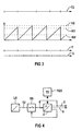
- the clock signals T2 can be obtained, for example, by a converter U2 from the bus signal and then pass through a closed at rest switching stage SS to a counter Z, which is counted up in relation to the clock signal T high-frequency clock signal T3 of a timer TG3. By the first clock of the clock signal T2, the counter Z is reset and started.
- the switching stage SS If there is a counter reading at the output greater than zero, but smaller than a lower comparator threshold K1 (dashed in FIG FIG. 3 Center shown), the switching stage SS is disabled. After reaching the lower comparator threshold K1, however, the switching stage SS is again continuous.
- a clock of the clock signal T2 arrives, it resets the counter. However, if this is not done soon, the counter Z2 reaches an upper comparator threshold K2 (in FIG. 3 Center also indicated by dashed lines), in which case a reset of the counter Z2 happens.
- the upper and lower comparator thresholds K2 and K1 are arranged around the count for timely incoming clock signals T2 around. Whenever a reset of the counter Z2 takes place, one clock of a clock signal T is triggered.
- the first (start) and the second clock of the clock signal T2 done so that this generate by resetting the counter Z corresponding clock signals T, while the third clock of the clock signal T2 arrives so late that by previous reaching the upper comparator threshold K2 of the third clock of the clock signal T is generated.
- the fifth clock of the clock signal T2 may again regularly trigger the fifth clock of the clock signal T.
- the real-time operating system which is installed next to the PC operating system, offers no possibility without special precautions to interactively start, terminate or otherwise influence real-time applications.
- the technique described below allows starting a real-time application in a PC system as described above with real-time expansion by mechanisms of the PC operating system.
- the real-time application is created with a development system for PC applications. This application can work with the standard mechanisms of the PC operating system.
- real-time application is a common program. After the start of the real-time application, this runs through an initialization phase in which no real-time-relevant activities are carried out. In this section of the program, the real-time application logs in via the interface of the real-time operating system. When registering the entry points are communicated to the real-time relevant program parts. After passing through this part of the program, the real-time application is ready for operation controlled by external signals.
- protected and unprotected memory areas S2 and S1 are provided at the personal computer PC. To execute the real-time application in a protected environment, the following should be noted.
- each program is executed in an environment that prevents unauthorized access between programs and unauthorized access to system data and resources (user-mode).
- a real-time application that relies on a real-time operating system must have unrestricted access to all resources managed by the real-time system. This means that the real-time application must run in an unprotected environment (kernelmode). Switching an application from protected to unprotected mode is not supported by PC operating systems (Windows NT).
- the technique described below can be used to achieve a change in the real-time application from the protected to the unprotected mode under the PC operating system Windows NT.
- a device driver is implemented for the real-time expansion of the PC operating system.
- a device driver represents an extension of the operating system.
- the program of the device driver is always executed in unprotected (kernel) mode.
- This real-time extension device driver provides an interface that allows an application (especially a real-time application) to tell the device driver (application) functions to enable it from unprotected mode. (Explanation: If a function is called from the unprotected mode that belongs to an application and thus to a protected program part, the unprotected mode remains active.)
- the execution of functions of the real-time application in the unprotected mode can be done synchronously, i. the function communicated from the real-time application to the driver is activated directly while the calling program part of the real-time application remains at the program location until the program returns from the driver function.
- a synchronous execution can be used if, after logging on the real-time application, the further initialization is to take place in the unprotected mode (in order, for example, to be able to access the resources of the real-time application without restrictions).
- Asynchronous execution in unprotected mode is achieved when the driver stores the functions of the real-time application and executes these functions in response to a signal.
- Switching from the PC operating system to the real-time operating system is one such asynchronous invocation of a function of the real-time operating system in unprotected mode: the toggle signal results in the activation of its associated interrupt handler. This is part of the driver program and runs in unprotected mode. In this interrupt handler, a change is made to the context of the real-time application and a function of the real-time application associated with the handover signal is activated.
- interrupt handling signals For the nested interrupts, the following can be additionally executed.
- a PC system only a limited number of interrupt handling signals are available to disposal. Of the fifteen interrupt signals of the standard PC, most are occupied by standard devices of the PC system.
- a real-time application typically requires multiple signals that it must respond to with a short latency time.
- the interrupt handling routine whose collective signal is assigned to the real-time signals, is entered directly into the interrupt table of the processor. This bypasses Windows NT's primary handling of the interrupt request and must be replaced with appropriate handling in the interrupt handler. In particular, the interrupt handler acknowledges the interrupt request to the interrupt mechanism of the PC, thereby making it ready to generate another request on the same interrupt line. The interrupt handler must be implemented reentry.
Landscapes
- Engineering & Computer Science (AREA)
- Theoretical Computer Science (AREA)
- Physics & Mathematics (AREA)
- General Engineering & Computer Science (AREA)
- General Physics & Mathematics (AREA)
- Computer And Data Communications (AREA)
- Synchronisation In Digital Transmission Systems (AREA)
Claims (4)
- Système PC standard, auquel un générateur ( TGI ) interne de cadence est mis à disposition pour engendrer un signal ( TI ) de cadence et dans lequel, par des signaux de commutation commandés en cadence, un passage entre un programme en temps réel et un programme qui n'est pas en temps réel a lieu continuellement dans une cadence ( T ) de temps fixe, le programme en temps réel permettant la commande et la régulation d'appareils périphériques, notamment d'entraînements, caractérisé en ce que le système PC ( PC, S1, S2 ) est relié aux appareils ( A1, An ) périphériques par un système de communication industrielle, dans lequel un maître bus ( B ) prend en charge la commande de communication à une cadence ( T2 ) de communication cyclique, indépendante du système PC ( PC, S1, S2 ) et en ce que la cadence ( T ) de temps fixe peut être engendrée à partir de la cadence ( T2 ) de communication.
- Système suivant la revendication 1, caractérisé en ce que la cadence ( T ) de temps fixe peut être engendrée indirectement à partir de la cadence ( T2 ) de communication par le fait que celle-ci est égalisée d'abord en ce qui concerne sa durée de cadence.
- Système suivant la revendication 2, caractérisé en ce que par une première cadence de communication un compteur ( Z ), ayant une fréquence relativement haute par rapport à la cadence ( T2 ) de communication, est lancé par remise à l'état initial, en ce que, lorsque arrive la cadence de communication régulière suivante, un seuil ( K1 ) inférieur et un seuil ( K2 ) supérieur de compérateur sont mis autour de l'état du compteur auquel on s'attend, en ce qu'avant d'atteindre le seuil ( K1 ) inférieur de compérateur, le compteur ( Z ) ne peut pas être mis à l'état initial, en ce qu'après avoir atteint le seuil ( K1 ) inférieur de compérateur, le compteur ( Z ) peut être mis à l'état initial par une cadence de communication arrivant nouvellement, en ce que sinon, lorsque le seuil ( K2 ) supérieur de compérateur est atteint, une remise automatique à l'état initial du compteur a lieu et en ce que la cadence ( T ) de temps est donnée par les opérations de remise à l'état initial.
- Système suivant la revendication 3, caractérisé en ce que pour un état ( KU ) du compteur pouvant être défini en dessous du seuil ( K1 ) inférieur de compérateur, respectivement un signal ( U ) de commutation peut être prescrit à l'intérieur de la cadence ( T ) de temps.
Applications Claiming Priority (2)
| Application Number | Priority Date | Filing Date | Title |
|---|---|---|---|
| DE19931933 | 1999-07-08 | ||
| DE19931933 | 1999-07-08 |
Publications (3)
| Publication Number | Publication Date |
|---|---|
| EP1067448A2 EP1067448A2 (fr) | 2001-01-10 |
| EP1067448A3 EP1067448A3 (fr) | 2003-06-04 |
| EP1067448B1 true EP1067448B1 (fr) | 2009-02-11 |
Family
ID=7914146
Family Applications (1)
| Application Number | Title | Priority Date | Filing Date |
|---|---|---|---|
| EP00113794A Expired - Lifetime EP1067448B1 (fr) | 1999-07-08 | 2000-06-29 | Système-PC pour programmes en temps réel et temps non réel |
Country Status (2)
| Country | Link |
|---|---|
| EP (1) | EP1067448B1 (fr) |
| DE (1) | DE50015549D1 (fr) |
Cited By (4)
| Publication number | Priority date | Publication date | Assignee | Title |
|---|---|---|---|---|
| US7859748B2 (en) | 2000-01-14 | 2010-12-28 | Carl Zeiss Smt Gmbh | Microlithographic reduction projection catadioptric objective |
| US7869122B2 (en) | 2004-01-14 | 2011-01-11 | Carl Zeiss Smt Ag | Catadioptric projection objective |
| US8199400B2 (en) | 2004-01-14 | 2012-06-12 | Carl Zeiss Smt Gmbh | Catadioptric projection objective |
| US8913316B2 (en) | 2004-05-17 | 2014-12-16 | Carl Zeiss Smt Gmbh | Catadioptric projection objective with intermediate images |
Families Citing this family (7)
| Publication number | Priority date | Publication date | Assignee | Title |
|---|---|---|---|---|
| JP2004514943A (ja) | 2000-11-28 | 2004-05-20 | カール・ツアイス・エスエムテイ・アーゲー | 157nmリソグラフィ用の反射屈折投影系 |
| DE10246746B3 (de) | 2002-10-07 | 2004-04-08 | Siemens Ag | Rechnersystem für Echtzeit- und Nicht-Echtzeitprogramme |
| DE102006013640A1 (de) | 2006-03-22 | 2007-09-27 | Robert Bosch Gmbh | Verfahren und Datenübertragungssystem zur Übergabe von Daten zwischen dem Datenübertragungssystem und einem Host-Prozessor eines Teilnehmers eines Datenübertragungssystems |
| DE102006040417A1 (de) * | 2006-08-29 | 2007-08-30 | Siemens Ag | Einrichtung zur Steuerung und/oder Regelung einer Maschine |
| DE102006040416A1 (de) * | 2006-08-29 | 2008-03-20 | Siemens Ag | Einrichtung zur Steuerung und/oder Regelung einer Maschine |
| DE102006058909A1 (de) * | 2006-12-13 | 2008-01-31 | Siemens Ag | Einrichtung zur Steuerung und/oder Regelung einer Maschine |
| DE102009047024A1 (de) * | 2009-11-23 | 2011-05-26 | Beckhoff Automation Gmbh | Parallelisierte Programmsteuerung |
Citations (1)
| Publication number | Priority date | Publication date | Assignee | Title |
|---|---|---|---|---|
| JPH01314451A (ja) * | 1988-06-14 | 1989-12-19 | Sumitomo Electric Ind Ltd | 位相ジッタ検知回路 |
Family Cites Families (5)
| Publication number | Priority date | Publication date | Assignee | Title |
|---|---|---|---|---|
| US4137504A (en) * | 1977-08-12 | 1979-01-30 | Digital Equipment Corporation | Digital filter |
| TW379293B (en) * | 1994-04-01 | 2000-01-11 | Ibm | Apparatus and method for generating a clock in a microprocessor |
| GB2310331B (en) * | 1996-02-15 | 2000-06-28 | Surrey University Of | Phase noise reduction circuits |
| DE19648422C2 (de) * | 1996-11-22 | 2000-03-30 | Hans Beckhoff | Verfahren und Vorrichtung zum Implementieren eines echtzeitfähigen Steuerprogramms in einem nicht-echtzeitfähigen Betriebsprogramm |
| US5915108A (en) * | 1997-06-30 | 1999-06-22 | Delco Electronics Corporation | Method of measurement and compensation of an inaccurate clock signal |
-
2000
- 2000-06-29 DE DE50015549T patent/DE50015549D1/de not_active Expired - Lifetime
- 2000-06-29 EP EP00113794A patent/EP1067448B1/fr not_active Expired - Lifetime
Patent Citations (1)
| Publication number | Priority date | Publication date | Assignee | Title |
|---|---|---|---|---|
| JPH01314451A (ja) * | 1988-06-14 | 1989-12-19 | Sumitomo Electric Ind Ltd | 位相ジッタ検知回路 |
Non-Patent Citations (2)
| Title |
|---|
| GRUHLER, DREIER: "CANopen Implementation Guidelines", 1 July 1997, STA REUTLINGEN, REUTLINGEN, GERMANY * |
| PATENT ABSTRACTS OF JAPAN * |
Cited By (15)
| Publication number | Priority date | Publication date | Assignee | Title |
|---|---|---|---|---|
| US7859748B2 (en) | 2000-01-14 | 2010-12-28 | Carl Zeiss Smt Gmbh | Microlithographic reduction projection catadioptric objective |
| US7869122B2 (en) | 2004-01-14 | 2011-01-11 | Carl Zeiss Smt Ag | Catadioptric projection objective |
| US8199400B2 (en) | 2004-01-14 | 2012-06-12 | Carl Zeiss Smt Gmbh | Catadioptric projection objective |
| US8208198B2 (en) | 2004-01-14 | 2012-06-26 | Carl Zeiss Smt Gmbh | Catadioptric projection objective |
| US8208199B2 (en) | 2004-01-14 | 2012-06-26 | Carl Zeiss Smt Gmbh | Catadioptric projection objective |
| US8289619B2 (en) | 2004-01-14 | 2012-10-16 | Carl Zeiss Smt Gmbh | Catadioptric projection objective |
| US8339701B2 (en) | 2004-01-14 | 2012-12-25 | Carl Zeiss Smt Gmbh | Catadioptric projection objective |
| US8355201B2 (en) | 2004-01-14 | 2013-01-15 | Carl Zeiss Smt Gmbh | Catadioptric projection objective |
| US8416490B2 (en) | 2004-01-14 | 2013-04-09 | Carl Zeiss Smt Gmbh | Catadioptric projection objective |
| US8730572B2 (en) | 2004-01-14 | 2014-05-20 | Carl Zeiss Smt Gmbh | Catadioptric projection objective |
| US8804234B2 (en) | 2004-01-14 | 2014-08-12 | Carl Zeiss Smt Gmbh | Catadioptric projection objective including an aspherized plate |
| US8908269B2 (en) | 2004-01-14 | 2014-12-09 | Carl Zeiss Smt Gmbh | Immersion catadioptric projection objective having two intermediate images |
| US8913316B2 (en) | 2004-05-17 | 2014-12-16 | Carl Zeiss Smt Gmbh | Catadioptric projection objective with intermediate images |
| US9019596B2 (en) | 2004-05-17 | 2015-04-28 | Carl Zeiss Smt Gmbh | Catadioptric projection objective with intermediate images |
| US9134618B2 (en) | 2004-05-17 | 2015-09-15 | Carl Zeiss Smt Gmbh | Catadioptric projection objective with intermediate images |
Also Published As
| Publication number | Publication date |
|---|---|
| EP1067448A3 (fr) | 2003-06-04 |
| EP1067448A2 (fr) | 2001-01-10 |
| DE50015549D1 (de) | 2009-03-26 |
Similar Documents
| Publication | Publication Date | Title |
|---|---|---|
| EP0851348B1 (fr) | Méthode et appareil pour implémentation d'un logiciel de contrÔle en temps réel dans un logiciel de contrÔle en temps non réel | |
| DE69305049T2 (de) | Hochfrequenz- cmos-schaltung mit geringen verbrauch | |
| DE2718051C3 (de) | Datenverarbeitungsanlage mit Einrichtungen zur wechselnden Bearbeitung mehrerer Aufgaben | |
| DE69428634T2 (de) | Hardware-Anordnung und Verfahren zur Ausdehnung der Datenverarbeitungszeit in den Fliessbandstufen eines Mikrorechnersystems | |
| DE3300261C2 (fr) | ||
| EP3538960B1 (fr) | Commande de déroulement de modules de programme | |
| EP0012186A1 (fr) | Circuit pour la génération d'impulsions d'horloge | |
| DE4011745A1 (de) | Taskverfolgungseinrichtung | |
| EP1067448A2 (fr) | Système-PC pour programmes en temps réel et temps non réel | |
| EP3176696A1 (fr) | Procédé de réalisation et d'exécution d'une application complexe en temps réel | |
| DE4005042C2 (de) | Mehrrechnersystem zur Durchführung von Bewegungssteuerungen | |
| DE60219246T2 (de) | Mit einem TCP/IP Netzwerk verbundene Automatisierungsvorrichtung | |
| DE10246746B3 (de) | Rechnersystem für Echtzeit- und Nicht-Echtzeitprogramme | |
| EP0350039A1 (fr) | Circuit compteur-horloge pour un microcontrôleur | |
| EP1220067B1 (fr) | Procédé d'intégration pour composants d'automatisation | |
| DE10065419A1 (de) | Industrielle Steuerung mit taktsynchronem Ablaufebenenmodell | |
| DE102010003530A1 (de) | Hardware-Datenverarbeitungseinheit und Verfahren zur Überwachung einer Rundendauer einer Routingeinheit | |
| DE69425377T2 (de) | Einzel-Zyklus-Prozessor zur Echtzeitsverarbeitung | |
| EP3977301A1 (fr) | Serveur de durée d'exécution destiné à la mise en oeuvre simultanée de plusieurs systèmes de durée d'exécution d'une installation d'automatisation | |
| EP2287742B1 (fr) | Unité commandée par programme | |
| EP1220065B1 (fr) | Procédé pour faire fonctionner un contrôleur industriel avec un système run-time | |
| EP0991995B1 (fr) | Procedure d'interruption dans un systeme information a commande des interruptions | |
| DE10334626B4 (de) | Informationsverarbeitungsvorrichtung | |
| DE2535924C2 (de) | Verfahren für den Betrieb der Steuereinrichtung einer Vermittlungsanlage, insbesondere Fernsprechvermittlungsanlage | |
| DE69127013T2 (de) | Unterbrechungssteuerschaltung und Mikrocomputersystem, das diese enthält |
Legal Events
| Date | Code | Title | Description |
|---|---|---|---|
| PUAI | Public reference made under article 153(3) epc to a published international application that has entered the european phase |
Free format text: ORIGINAL CODE: 0009012 |
|
| AK | Designated contracting states |
Kind code of ref document: A2 Designated state(s): AT BE CH CY DE DK ES FI FR GB GR IE IT LI LU MC NL PT SE |
|
| AX | Request for extension of the european patent |
Free format text: AL;LT;LV;MK;RO;SI |
|
| PUAL | Search report despatched |
Free format text: ORIGINAL CODE: 0009013 |
|
| AK | Designated contracting states |
Designated state(s): AT BE CH CY DE DK ES FI FR GB GR IE IT LI LU MC NL PT SE |
|
| AX | Request for extension of the european patent |
Extension state: AL LT LV MK RO SI |
|
| 17P | Request for examination filed |
Effective date: 20030707 |
|
| AKX | Designation fees paid |
Designated state(s): DE FR |
|
| 17Q | First examination report despatched |
Effective date: 20040322 |
|
| GRAP | Despatch of communication of intention to grant a patent |
Free format text: ORIGINAL CODE: EPIDOSNIGR1 |
|
| GRAS | Grant fee paid |
Free format text: ORIGINAL CODE: EPIDOSNIGR3 |
|
| GRAA | (expected) grant |
Free format text: ORIGINAL CODE: 0009210 |
|
| AK | Designated contracting states |
Kind code of ref document: B1 Designated state(s): DE FR |
|
| REF | Corresponds to: |
Ref document number: 50015549 Country of ref document: DE Date of ref document: 20090326 Kind code of ref document: P |
|
| PLBE | No opposition filed within time limit |
Free format text: ORIGINAL CODE: 0009261 |
|
| STAA | Information on the status of an ep patent application or granted ep patent |
Free format text: STATUS: NO OPPOSITION FILED WITHIN TIME LIMIT |
|
| 26N | No opposition filed |
Effective date: 20091112 |
|
| REG | Reference to a national code |
Ref country code: FR Ref legal event code: PLFP Year of fee payment: 17 |
|
| REG | Reference to a national code |
Ref country code: FR Ref legal event code: PLFP Year of fee payment: 18 |
|
| REG | Reference to a national code |
Ref country code: FR Ref legal event code: PLFP Year of fee payment: 19 |
|
| PGFP | Annual fee paid to national office [announced via postgrant information from national office to epo] |
Ref country code: FR Payment date: 20190619 Year of fee payment: 20 |
|
| PGFP | Annual fee paid to national office [announced via postgrant information from national office to epo] |
Ref country code: DE Payment date: 20190819 Year of fee payment: 20 |
|
| REG | Reference to a national code |
Ref country code: DE Ref legal event code: R071 Ref document number: 50015549 Country of ref document: DE |