EP1067669A2 - Convertisseur à modulation de largueur d'impulsions - Google Patents
Convertisseur à modulation de largueur d'impulsions Download PDFInfo
- Publication number
- EP1067669A2 EP1067669A2 EP00105579A EP00105579A EP1067669A2 EP 1067669 A2 EP1067669 A2 EP 1067669A2 EP 00105579 A EP00105579 A EP 00105579A EP 00105579 A EP00105579 A EP 00105579A EP 1067669 A2 EP1067669 A2 EP 1067669A2
- Authority
- EP
- European Patent Office
- Prior art keywords
- inverter
- factor
- frequency
- sec
- triangular
- Prior art date
- Legal status (The legal status is an assumption and is not a legal conclusion. Google has not performed a legal analysis and makes no representation as to the accuracy of the status listed.)
- Granted
Links
- 238000004519 manufacturing process Methods 0.000 description 3
- 238000013021 overheating Methods 0.000 description 2
- 230000000737 periodic effect Effects 0.000 description 2
- 239000004065 semiconductor Substances 0.000 description 2
- 238000013459 approach Methods 0.000 description 1
- 239000003990 capacitor Substances 0.000 description 1
- 238000010586 diagram Methods 0.000 description 1
- 238000009499 grossing Methods 0.000 description 1
- 238000010438 heat treatment Methods 0.000 description 1
- 238000000034 method Methods 0.000 description 1
- 238000012986 modification Methods 0.000 description 1
- 230000004048 modification Effects 0.000 description 1
- 230000005855 radiation Effects 0.000 description 1
Images


Classifications
-
- H—ELECTRICITY
- H02—GENERATION; CONVERSION OR DISTRIBUTION OF ELECTRIC POWER
- H02M—APPARATUS FOR CONVERSION BETWEEN AC AND AC, BETWEEN AC AND DC, OR BETWEEN DC AND DC, AND FOR USE WITH MAINS OR SIMILAR POWER SUPPLY SYSTEMS; CONVERSION OF DC OR AC INPUT POWER INTO SURGE OUTPUT POWER; CONTROL OR REGULATION THEREOF
- H02M7/00—Conversion of AC power input into DC power output; Conversion of DC power input into AC power output
- H02M7/42—Conversion of DC power input into AC power output without possibility of reversal
- H02M7/44—Conversion of DC power input into AC power output without possibility of reversal by static converters
- H02M7/48—Conversion of DC power input into AC power output without possibility of reversal by static converters using discharge tubes with control electrode or semiconductor devices with control electrode
- H02M7/53—Conversion of DC power input into AC power output without possibility of reversal by static converters using discharge tubes with control electrode or semiconductor devices with control electrode using devices of a triode or transistor type requiring continuous application of a control signal
- H02M7/537—Conversion of DC power input into AC power output without possibility of reversal by static converters using discharge tubes with control electrode or semiconductor devices with control electrode using devices of a triode or transistor type requiring continuous application of a control signal using semiconductor devices only, e.g. single switched pulse inverters
- H02M7/5387—Conversion of DC power input into AC power output without possibility of reversal by static converters using discharge tubes with control electrode or semiconductor devices with control electrode using devices of a triode or transistor type requiring continuous application of a control signal using semiconductor devices only, e.g. single switched pulse inverters in a bridge configuration
- H02M7/53871—Conversion of DC power input into AC power output without possibility of reversal by static converters using discharge tubes with control electrode or semiconductor devices with control electrode using devices of a triode or transistor type requiring continuous application of a control signal using semiconductor devices only, e.g. single switched pulse inverters in a bridge configuration with automatic control of output voltage or current
- H02M7/53875—Conversion of DC power input into AC power output without possibility of reversal by static converters using discharge tubes with control electrode or semiconductor devices with control electrode using devices of a triode or transistor type requiring continuous application of a control signal using semiconductor devices only, e.g. single switched pulse inverters in a bridge configuration with automatic control of output voltage or current with analogue control of three-phase output
-
- H—ELECTRICITY
- H02—GENERATION; CONVERSION OR DISTRIBUTION OF ELECTRIC POWER
- H02P—CONTROL OR REGULATION OF ELECTRIC MOTORS, ELECTRIC GENERATORS OR DYNAMO-ELECTRIC CONVERTERS; CONTROLLING TRANSFORMERS, REACTORS OR CHOKE COILS
- H02P27/00—Arrangements or methods for the control of AC motors characterised by the kind of supply voltage
- H02P27/04—Arrangements or methods for the control of AC motors characterised by the kind of supply voltage using variable-frequency supply voltage, e.g. inverter or converter supply voltage
- H02P27/06—Arrangements or methods for the control of AC motors characterised by the kind of supply voltage using variable-frequency supply voltage, e.g. inverter or converter supply voltage using DC to AC converters or inverters
- H02P27/08—Arrangements or methods for the control of AC motors characterised by the kind of supply voltage using variable-frequency supply voltage, e.g. inverter or converter supply voltage using DC to AC converters or inverters with pulse width modulation
-
- H—ELECTRICITY
- H02—GENERATION; CONVERSION OR DISTRIBUTION OF ELECTRIC POWER
- H02P—CONTROL OR REGULATION OF ELECTRIC MOTORS, ELECTRIC GENERATORS OR DYNAMO-ELECTRIC CONVERTERS; CONTROLLING TRANSFORMERS, REACTORS OR CHOKE COILS
- H02P29/00—Arrangements for regulating or controlling electric motors, appropriate for both AC and DC motors
- H02P29/02—Providing protection against overload without automatic interruption of supply
-
- H—ELECTRICITY
- H02—GENERATION; CONVERSION OR DISTRIBUTION OF ELECTRIC POWER
- H02P—CONTROL OR REGULATION OF ELECTRIC MOTORS, ELECTRIC GENERATORS OR DYNAMO-ELECTRIC CONVERTERS; CONTROLLING TRANSFORMERS, REACTORS OR CHOKE COILS
- H02P29/00—Arrangements for regulating or controlling electric motors, appropriate for both AC and DC motors
- H02P29/50—Reduction of harmonics
-
- H—ELECTRICITY
- H02—GENERATION; CONVERSION OR DISTRIBUTION OF ELECTRIC POWER
- H02M—APPARATUS FOR CONVERSION BETWEEN AC AND AC, BETWEEN AC AND DC, OR BETWEEN DC AND DC, AND FOR USE WITH MAINS OR SIMILAR POWER SUPPLY SYSTEMS; CONVERSION OF DC OR AC INPUT POWER INTO SURGE OUTPUT POWER; CONTROL OR REGULATION THEREOF
- H02M1/00—Details of apparatus for conversion
- H02M1/44—Circuits or arrangements for compensating for electromagnetic interference in converters or inverters
Definitions
- the present invention relates generally to a pulse-width modulation (PWM) inverter for generating a PWM waveform by comparing a sine wave and a triangular wave for driving of an electric motor, and more particularly, to means for generating a triangular wave or a carrier, which allow an improvement in the quality of an electromagnetic sound produced by the motor.
- PWM pulse-width modulation
- FIG. 3 shows a fundamental structure of a PWM inverter.
- the inverter comprises a voltage-type main circuit 1 including a direct-current (DC) power source with a rectifier REC and a smoothing capacitor C, and a bridge arm with semiconductor switches SU-SZ using power transistors and diodes D1-D6.
- the main circuit 1 supplies the motor with alternating-current (AC) power with the frequency and voltage controlled by ignition-phase control of the bridge arm.
- AC alternating-current
- a control circuit for the main circuit 1 comprises a three-phase-voltage command generating circuit 2, a comparator circuit 3, a triangular-wave generating circuit 4, and a dead-time generating circuit 5.
- the three-phase-voltage command generating circuit 2 receives detected signals of the motor, such as a detected-speed signal, to obtain a three-phase-voltage signal in the form of a sine wave with the phase and amplitude controlled.
- the comparator circuit 3 compares the amplitudes between the three-phase-voltage signal and a triangular-wave or carrier signal out of the triangular-wave generating circuit 4 to generate a PWM-waveform signal.
- the dead-time generating circuit 5 provides a dead time to the PWM-waveform signal, obtaining gate signals of the switches SU-SZ in the main circuit 1.
- the motor driven by the inverter produces an electromagnetic sound having a triangular-wave or carrier frequency as a main component.
- An electromagnetic sound with single and high-pitched tone, particularly, in the frequency range of about 2 to 4 kHz is often offensive to operators.
- some conventional PWM inverters have a carrier frequency maximally increased by providing a sufficient output capacity and/or by adopting high-speed switching elements.
- an object of the present invention to provide a PWM inverter which can make an electromagnetic sound produced by an electric motor inoffensive to operators without any increase in manufacturing cost.
- Another object of the present invention is to provide a PWM inverter which allows the effective use of an electromagnetic sound produced by the motor.
- An aspect of the present invention lies in providing an inverter for generating a pulse-width modulation (PWM) waveform by comparing a sine wave and a triangular wave for driving of an electric motor, the inverter including means for generating a triangular wave, characterized in that the triangular-wave generating means comprise
- the advantages offered by the present invention are mainly that an electromagnetic sound produced by the motor driven by the PWM inverter can be changed to that one with inoffensive tone in the audio-frequency range. Therefore, an increase in the carrier frequency is unnecessary, which incurs an increase not only in manufacturing cost of the inverters, but in EMI noises.
- FIG. 1 shows a first embodiment of the present invention, the structure of which is substantially the same as that as shown in FIG. 3 except that it includes means for switching triangular-wave or carrier frequencies derived from the triangular-wave generating circuit 4 in accordance with control conditions.
- the switching means comprise a fundamental-carrier-frequency setting device 6, a factor-data table 7, a factor selector circuit 8, and a multiplier 9.
- the fundamental-carrier-frequency setting device 6 has a fundamental carrier frequency set as a fixed value to establish a reference value of the carrier frequencies generated by the triangular-wave generating circuit 4.
- the fundamental carrier frequency is determined to be relatively low, wherein the semiconductor switches SU-SZ in the main circuit 1 need no high-frequency elements and wherein an electromagnetic sound produced by the electric motor is in the audio-frequency range.
- the factor-data table 7 has a plurality of factor data used when obtaining the product of the fundamental carrier frequency set by the fundamental-carrier-frequency setting device 6 and a factor, wherein it is assumed that the fundamental carrier frequency is 1.
- the factor selector circuit 8 serves to select a factor data from the factor-data table 7, which is provided to the multiplier 9 as a multiplier signal.
- the factor selector circuit 8 receives a factor selecting signal or a control signal corresponding to operating conditions of the motor and the inverter such as a motor loaded condition (normal/overload) and an inverter cooling-fin condition (normal/overheating).
- the multiplier 9 serves to multiply the fundamental carrier frequency set by the fundamental-carrier-frequency setting device 6 by a factor selected by the factor selector circuit 8, which is provided to the triangular-wave generating circuit 4 as a carrier-frequency control signal.
- the triangular-wave or carrier frequencies are switched in accordance with factors selected by the factor selector circuit 8.
- a tone of an electromagnetic sound is changed, which has a triangular-wave or carrier frequency as a main component.
- the first embodiment does not make an electromagnetic sound less audible by increasing the carrier frequency, but uses the sound as means for warning operators of operating conditions of the motor and the inverter.
- a tone of an electromagnetic sound is controlled to be offensive or gloomy and sad to operators. During normal operation, it is controlled to be inoffensive or bright and cheerful to them.
- the carrier frequency is determined to produce an electromagnetic sound with single and high-pitched tone in the frequency range of about 2 to 4 kHz, which is often offensive to operators.
- This single and high-pitched electromagnetic sound is similar to that one produced in connection with the ordinary control circuit. In the first embodiment, it is obtained by selecting a factor 1 in the factor selector circuit 8 only when warning of an anomaly.
- the factor selector circuit 8 switches carrier frequencies 1, 2, 3 of three notes, such as do, mi flat, and sol, which form a minor chord giving a gloomy and sad impression in a periodic way of frequency 1 ⁇ frequency 2 ⁇ frequency 3 ⁇ frequency 1 ...
- the carrier frequencies 1, 2, 3 have values obtained by multiplying the fundamental carrier frequency FC_ SET (Hz) by factors as given in Table 1.
- FC_ SET fundamental carrier frequency
- the factor selector circuit 8 switches carrier frequencies 1, 2, 3 of three notes, such as do, mi, and sol, which form a major chord giving a bright and cheerful impression in a periodic way of frequency 1 ⁇ frequency 2 ⁇ frequency 3 ⁇ frequency 1 ...
- the carrier frequencies 1, 2, 3 have values obtained by multiplying the fundamental carrier frequency FC_ SET (Hz) by factors as given in Table 2.
- FC_ SET fundamental carrier frequency
- Tc time since an electromagnetic sound varies in accordance with a switching interval of the carrier frequencies 1, 2, 3, so that for obtaining an emphasized major chord, this switching interval needs to have a value Tc (sec) which allows clear heating of the three notes, e.g. about 17 msec with about 60 notes (20 periods) per sec.
- Tc sec
- the carrier frequencies 1, 2, 3 are switched every relatively short period of time of 2 to 10 msec, which corresponds to an integral multiple of a control period Ts (sec) of the inverter.
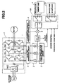
- FIG. 2 shows a second embodiment of the present invention.
- the switching interval Tc of the carrier frequencies 1, 2, 3 is determined to be long for obtaining clear notes and to be short for obtaining an inoffensive tone. However, it has a given period corresponding to an integral multiple of the control period Ts (sec) of the inverter regardless of an output frequency Fo (Hz) thereof.
- This change can automatically be carried out in accordance with the inverter output frequency Fo (Hz).
- the structure of the second embodiment which allows the above frequency change is substantially similar to that of the first embodiment except that in addition to the factor-data table 7, it includes a factor-data table 7A having a plurality of data on the factors as given in Table 3, which are a combination of the factors as given in Tables 1 and 2.
- a factor selector circuit 8A selects one of a mode of switching the three notes and a mode of switching the four notes so as to restrain occurrence of a beat sound resulting from the relationship between the inverter output frequency Fo (Hz) and the switching interval Tc (sec) of the carrier frequencies 1, 2, 3.
Landscapes
- Engineering & Computer Science (AREA)
- Power Engineering (AREA)
- Inverter Devices (AREA)
- Control Of Ac Motors In General (AREA)
Applications Claiming Priority (2)
| Application Number | Priority Date | Filing Date | Title |
|---|---|---|---|
| JP18982899A JP3893801B2 (ja) | 1999-07-05 | 1999-07-05 | Pwmインバータ |
| JP18982899 | 1999-07-05 |
Publications (3)
| Publication Number | Publication Date |
|---|---|
| EP1067669A2 true EP1067669A2 (fr) | 2001-01-10 |
| EP1067669A3 EP1067669A3 (fr) | 2001-06-13 |
| EP1067669B1 EP1067669B1 (fr) | 2004-02-11 |
Family
ID=16247899
Family Applications (1)
| Application Number | Title | Priority Date | Filing Date |
|---|---|---|---|
| EP00105579A Expired - Lifetime EP1067669B1 (fr) | 1999-07-05 | 2000-03-16 | Convertisseur à modulation de largueur d'impulsions |
Country Status (3)
| Country | Link |
|---|---|
| EP (1) | EP1067669B1 (fr) |
| JP (1) | JP3893801B2 (fr) |
| ES (1) | ES2214180T3 (fr) |
Cited By (15)
| Publication number | Priority date | Publication date | Assignee | Title |
|---|---|---|---|---|
| EP2040360A1 (fr) * | 2007-09-24 | 2009-03-25 | Robert Bosch GmbH | Procédé et dispositif de commande d'un moteur électrique |
| WO2009040280A1 (fr) * | 2007-09-24 | 2009-04-02 | Robert Bosch Gmbh | Procédé et dispositif pour commander un moteur électrique |
| WO2009112397A1 (fr) * | 2008-03-11 | 2009-09-17 | Siemens Aktiengesellschaft | Dispositif et procédé pour l'émission de signaux acoustiques |
| CN100555836C (zh) * | 2006-04-26 | 2009-10-28 | 日产自动车株式会社 | 功率变换装置的控制装置及控制方法 |
| DE102008024102A1 (de) * | 2008-05-17 | 2009-12-03 | Diehl Ako Stiftung & Co. Kg | Motorsteuerung zum Ansteuern eines Elektromotors |
| DE102008019487A1 (de) * | 2008-04-17 | 2009-12-31 | Sew-Eurodrive Gmbh & Co. Kg | Verfahren zum Betreiben eines Antriebs, Kühlkörper und Umrichter, Verfahren zur Identifikation oder Bestimmung der Entwicklungsversion eines Umrichters, Verfahren zum Betreiben einer Anlage |
| EP2268118A1 (fr) * | 2009-06-26 | 2010-12-29 | GEZE GmbH | Installation de porte |
| DE102010010629A1 (de) * | 2010-03-09 | 2011-09-15 | GM Global Technology Operations LLC , (n. d. Ges. d. Staates Delaware) | Verfahren und Vorrichtung zum Betreiben eines Fahrzeugs mit Elektromotor |
| WO2014173411A1 (fr) * | 2013-04-24 | 2014-10-30 | Ksl Fibertec Gmbh | Procédé de surveillance de moteurs d'entraînement |
| EP3142248A3 (fr) * | 2015-09-09 | 2017-04-12 | Lg Electronics Inc. | Appareil d'entraînement de moteur, appareil domestique le comprenant et terminal mobile |
| WO2017152394A1 (fr) * | 2016-03-09 | 2017-09-14 | 深圳市大疆创新科技有限公司 | Procédé et système de commande pour moteur |
| EP2319724A4 (fr) * | 2008-08-28 | 2017-11-29 | Nissan Motor Co., Ltd. | Appareil de limitation du bruit de marche d un véhicule et procédé associé |
| FR3076043A1 (fr) * | 2017-12-27 | 2019-06-28 | Somfy Activites Sa | Procede de commande electronique d'un moteur. |
| US11192454B2 (en) | 2018-09-25 | 2021-12-07 | Subaru Corporation | Vehicle control apparatus |
| EP4073915A4 (fr) * | 2021-02-25 | 2023-02-22 | Techtronic Cordless GP | Outils électriques et procédés de production d'une notification à un utilisateur |
Families Citing this family (9)
| Publication number | Priority date | Publication date | Assignee | Title |
|---|---|---|---|---|
| JP4576970B2 (ja) * | 2004-01-06 | 2010-11-10 | 株式会社明電舎 | パルス幅変調インバータ装置及びその制御方法 |
| JP5071608B2 (ja) * | 2005-02-07 | 2012-11-14 | 株式会社安川電機 | Pwmインバータ装置とその制御方法 |
| JP5455400B2 (ja) * | 2009-03-13 | 2014-03-26 | 東洋電機製造株式会社 | 電動機制御装置 |
| WO2016002074A1 (fr) * | 2014-07-04 | 2016-01-07 | 三菱電機株式会社 | Convertisseur de courant, déshumidificateur, climatiseur et équipement de réfrigération |
| CN107852100B (zh) * | 2015-07-17 | 2020-04-07 | 株式会社日立产机系统 | 电力转换装置及其输出电流噪声的降低方法 |
| JP6711932B2 (ja) * | 2019-01-09 | 2020-06-17 | 株式会社日立産機システム | 電力変換装置、及び、その出力電流ノイズの低減方法 |
| JP7414463B2 (ja) * | 2019-10-18 | 2024-01-16 | 株式会社Subaru | 制御装置 |
| DE102020118912A1 (de) | 2020-07-17 | 2022-01-20 | Sma Solar Technology Ag | Leistungselektronische wandlerschaltung und verfahren zur erzeugung von akustischen schwingungen bei einer leistungselektronischen wandlerschaltung |
| JP2023179995A (ja) * | 2022-06-08 | 2023-12-20 | 東芝産業機器システム株式会社 | モータ制御装置 |
Family Cites Families (4)
| Publication number | Priority date | Publication date | Assignee | Title |
|---|---|---|---|---|
| JPH01194871A (ja) * | 1988-01-27 | 1989-08-04 | Mitsubishi Electric Corp | パルス幅変調形インバータ装置 |
| JPH04200294A (ja) * | 1990-11-29 | 1992-07-21 | Toshiba Corp | インバータ装置 |
| JP2982445B2 (ja) * | 1991-12-12 | 1999-11-22 | 松下電器産業株式会社 | ブラシレスモータ |
| JPH05344740A (ja) * | 1992-06-09 | 1993-12-24 | Toshiba Corp | インバータ装置 |
-
1999
- 1999-07-05 JP JP18982899A patent/JP3893801B2/ja not_active Expired - Lifetime
-
2000
- 2000-03-16 EP EP00105579A patent/EP1067669B1/fr not_active Expired - Lifetime
- 2000-03-16 ES ES00105579T patent/ES2214180T3/es not_active Expired - Lifetime
Cited By (22)
| Publication number | Priority date | Publication date | Assignee | Title |
|---|---|---|---|---|
| CN100555836C (zh) * | 2006-04-26 | 2009-10-28 | 日产自动车株式会社 | 功率变换装置的控制装置及控制方法 |
| EP2040360A1 (fr) * | 2007-09-24 | 2009-03-25 | Robert Bosch GmbH | Procédé et dispositif de commande d'un moteur électrique |
| WO2009040280A1 (fr) * | 2007-09-24 | 2009-04-02 | Robert Bosch Gmbh | Procédé et dispositif pour commander un moteur électrique |
| US10097121B2 (en) | 2007-09-24 | 2018-10-09 | Robert Bosch Gmbh | Method and device for controlling an electric motor |
| WO2009112397A1 (fr) * | 2008-03-11 | 2009-09-17 | Siemens Aktiengesellschaft | Dispositif et procédé pour l'émission de signaux acoustiques |
| DE102008019487A1 (de) * | 2008-04-17 | 2009-12-31 | Sew-Eurodrive Gmbh & Co. Kg | Verfahren zum Betreiben eines Antriebs, Kühlkörper und Umrichter, Verfahren zur Identifikation oder Bestimmung der Entwicklungsversion eines Umrichters, Verfahren zum Betreiben einer Anlage |
| DE102008019487B4 (de) * | 2008-04-17 | 2017-05-11 | Sew-Eurodrive Gmbh & Co Kg | Verfahren zum Betreiben eines Antriebs, Kühlkörper, System von Umrichtern, Verfahren zur Identifikation oder Bestimmung der Entwicklungsversion eines Umrichters durch Modulation der Pulsweitenfrequenz |
| DE102008024102A1 (de) * | 2008-05-17 | 2009-12-03 | Diehl Ako Stiftung & Co. Kg | Motorsteuerung zum Ansteuern eines Elektromotors |
| US8179060B2 (en) | 2008-05-17 | 2012-05-15 | Diehl Ako Stiftung & Co. Kg | Motor controller for controlling an electric motor |
| EP2319724A4 (fr) * | 2008-08-28 | 2017-11-29 | Nissan Motor Co., Ltd. | Appareil de limitation du bruit de marche d un véhicule et procédé associé |
| EP2268118A1 (fr) * | 2009-06-26 | 2010-12-29 | GEZE GmbH | Installation de porte |
| DE102010010629A1 (de) * | 2010-03-09 | 2011-09-15 | GM Global Technology Operations LLC , (n. d. Ges. d. Staates Delaware) | Verfahren und Vorrichtung zum Betreiben eines Fahrzeugs mit Elektromotor |
| WO2014173411A1 (fr) * | 2013-04-24 | 2014-10-30 | Ksl Fibertec Gmbh | Procédé de surveillance de moteurs d'entraînement |
| EP3142248A3 (fr) * | 2015-09-09 | 2017-04-12 | Lg Electronics Inc. | Appareil d'entraînement de moteur, appareil domestique le comprenant et terminal mobile |
| CN106972801A (zh) * | 2015-09-09 | 2017-07-21 | Lg电子株式会社 | 马达驱动装置、包括其的家用电器以及移动终端 |
| US10120361B2 (en) | 2015-09-09 | 2018-11-06 | Lg Electronics Inc. | Motor driving apparatus, home appliance including the same, and mobile terminal |
| WO2017152394A1 (fr) * | 2016-03-09 | 2017-09-14 | 深圳市大疆创新科技有限公司 | Procédé et système de commande pour moteur |
| CN107710597A (zh) * | 2016-03-09 | 2018-02-16 | 深圳市大疆创新科技有限公司 | 电机的控制方法及系统 |
| FR3076043A1 (fr) * | 2017-12-27 | 2019-06-28 | Somfy Activites Sa | Procede de commande electronique d'un moteur. |
| WO2019129782A1 (fr) * | 2017-12-27 | 2019-07-04 | Somfy Activites Sa | Procédé de commande électronique d'un moteur |
| US11192454B2 (en) | 2018-09-25 | 2021-12-07 | Subaru Corporation | Vehicle control apparatus |
| EP4073915A4 (fr) * | 2021-02-25 | 2023-02-22 | Techtronic Cordless GP | Outils électriques et procédés de production d'une notification à un utilisateur |
Also Published As
| Publication number | Publication date |
|---|---|
| EP1067669B1 (fr) | 2004-02-11 |
| JP2001025258A (ja) | 2001-01-26 |
| JP3893801B2 (ja) | 2007-03-14 |
| EP1067669A3 (fr) | 2001-06-13 |
| ES2214180T3 (es) | 2004-09-16 |
Similar Documents
| Publication | Publication Date | Title |
|---|---|---|
| EP1067669B1 (fr) | Convertisseur à modulation de largueur d'impulsions | |
| US6617821B2 (en) | Method and apparatus for compensating for device dynamics by adjusting inverter carrier frequency | |
| JP3311743B2 (ja) | 共振インバータの制御方法 | |
| JPH10337033A (ja) | パワー電子回路装置の動作方法 | |
| JP3229019B2 (ja) | Pwmインバータ装置 | |
| JPH0947026A (ja) | Pwm波形生成装置 | |
| KR20030011274A (ko) | 전력 컨버터에서 고조파 감소를 위한 장치 및 공정 | |
| JP2810081B2 (ja) | Pwm電力変換装置 | |
| JP2001128462A (ja) | インバータ装置の制御方法 | |
| JPH10201248A (ja) | 電源装置 | |
| JPS63148894A (ja) | Pwmインバ−タの制御装置 | |
| JP2001016860A (ja) | インバータ制御装置 | |
| JP3286046B2 (ja) | 電力変換装置の制御方法 | |
| JPH05161364A (ja) | インバータ装置 | |
| JPH04190680A (ja) | インバータ電源回路 | |
| JPH07231666A (ja) | Pwm制御電圧形インバータ | |
| US6472844B2 (en) | Single-phased powered drive system | |
| JPH0851774A (ja) | スイッチング電源回路 | |
| KR100583974B1 (ko) | 인버터장치의 펄스폭변조신호발생방법 | |
| JP3617166B2 (ja) | 交流電源装置 | |
| JPH06113548A (ja) | インバータ装置 | |
| JPS61244275A (ja) | Pwm制御電圧形インバ−タ装置 | |
| JP2738354B2 (ja) | 広入力圧電トランスコンバータ | |
| JP2931075B2 (ja) | レーザ用高周波電源の制御方法 | |
| JPS5889070A (ja) | Pwmインバータの制御方法および装置 |
Legal Events
| Date | Code | Title | Description |
|---|---|---|---|
| PUAI | Public reference made under article 153(3) epc to a published international application that has entered the european phase |
Free format text: ORIGINAL CODE: 0009012 |
|
| 17P | Request for examination filed |
Effective date: 20000316 |
|
| AK | Designated contracting states |
Kind code of ref document: A2 Designated state(s): ES GB IT |
|
| AX | Request for extension of the european patent |
Free format text: AL;LT;LV;MK;RO;SI |
|
| PUAL | Search report despatched |
Free format text: ORIGINAL CODE: 0009013 |
|
| AK | Designated contracting states |
Kind code of ref document: A3 Designated state(s): AT BE CH CY DE DK ES FI FR GB GR IE IT LI LU MC NL PT SE |
|
| AX | Request for extension of the european patent |
Free format text: AL;LT;LV;MK;RO;SI |
|
| 17Q | First examination report despatched |
Effective date: 20011219 |
|
| AKX | Designation fees paid |
Free format text: ES GB IT |
|
| REG | Reference to a national code |
Ref country code: DE Ref legal event code: 8566 |
|
| GRAP | Despatch of communication of intention to grant a patent |
Free format text: ORIGINAL CODE: EPIDOSNIGR1 |
|
| GRAS | Grant fee paid |
Free format text: ORIGINAL CODE: EPIDOSNIGR3 |
|
| GRAA | (expected) grant |
Free format text: ORIGINAL CODE: 0009210 |
|
| AK | Designated contracting states |
Kind code of ref document: B1 Designated state(s): ES GB IT |
|
| REG | Reference to a national code |
Ref country code: GB Ref legal event code: FG4D |
|
| REG | Reference to a national code |
Ref country code: ES Ref legal event code: FG2A Ref document number: 2214180 Country of ref document: ES Kind code of ref document: T3 |
|
| PLBE | No opposition filed within time limit |
Free format text: ORIGINAL CODE: 0009261 |
|
| STAA | Information on the status of an ep patent application or granted ep patent |
Free format text: STATUS: NO OPPOSITION FILED WITHIN TIME LIMIT |
|
| 26N | No opposition filed |
Effective date: 20041112 |
|
| PGFP | Annual fee paid to national office [announced via postgrant information from national office to epo] |
Ref country code: GB Payment date: 20190320 Year of fee payment: 20 Ref country code: IT Payment date: 20190325 Year of fee payment: 20 |
|
| PGFP | Annual fee paid to national office [announced via postgrant information from national office to epo] |
Ref country code: ES Payment date: 20190418 Year of fee payment: 20 |
|
| REG | Reference to a national code |
Ref country code: GB Ref legal event code: PE20 Expiry date: 20200315 |
|
| PG25 | Lapsed in a contracting state [announced via postgrant information from national office to epo] |
Ref country code: GB Free format text: LAPSE BECAUSE OF EXPIRATION OF PROTECTION Effective date: 20200315 |
|
| REG | Reference to a national code |
Ref country code: ES Ref legal event code: FD2A Effective date: 20220103 |
|
| PG25 | Lapsed in a contracting state [announced via postgrant information from national office to epo] |
Ref country code: ES Free format text: LAPSE BECAUSE OF EXPIRATION OF PROTECTION Effective date: 20200317 |