EP1067676A1 - Procédé de linéarisation en bande large d'amplificateurs de puissance - Google Patents
Procédé de linéarisation en bande large d'amplificateurs de puissance Download PDFInfo
- Publication number
- EP1067676A1 EP1067676A1 EP99401627A EP99401627A EP1067676A1 EP 1067676 A1 EP1067676 A1 EP 1067676A1 EP 99401627 A EP99401627 A EP 99401627A EP 99401627 A EP99401627 A EP 99401627A EP 1067676 A1 EP1067676 A1 EP 1067676A1
- Authority
- EP
- European Patent Office
- Prior art keywords
- frequency
- input signal
- coefficients
- power amplifier
- amplifier
- Prior art date
- Legal status (The legal status is an assumption and is not a legal conclusion. Google has not performed a legal analysis and makes no representation as to the accuracy of the status listed.)
- Granted
Links
- 238000000034 method Methods 0.000 title claims abstract description 22
- 238000005259 measurement Methods 0.000 claims description 10
- 238000012360 testing method Methods 0.000 claims description 8
- 230000001427 coherent effect Effects 0.000 claims description 5
- 230000001419 dependent effect Effects 0.000 claims description 4
- 230000000694 effects Effects 0.000 claims description 4
- 238000012937 correction Methods 0.000 claims description 2
- 238000006243 chemical reaction Methods 0.000 description 5
- 230000005540 biological transmission Effects 0.000 description 3
- 238000010586 diagram Methods 0.000 description 3
- 230000032683 aging Effects 0.000 description 2
- 230000006399 behavior Effects 0.000 description 2
- 230000001413 cellular effect Effects 0.000 description 2
- 238000005516 engineering process Methods 0.000 description 2
- 230000003595 spectral effect Effects 0.000 description 2
- 238000007792 addition Methods 0.000 description 1
- 238000004364 calculation method Methods 0.000 description 1
- 238000004891 communication Methods 0.000 description 1
- 230000008878 coupling Effects 0.000 description 1
- 238000010168 coupling process Methods 0.000 description 1
- 238000005859 coupling reaction Methods 0.000 description 1
- 230000007423 decrease Effects 0.000 description 1
- 238000001514 detection method Methods 0.000 description 1
- 230000001627 detrimental effect Effects 0.000 description 1
- 238000011161 development Methods 0.000 description 1
- 230000018109 developmental process Effects 0.000 description 1
- 230000006870 function Effects 0.000 description 1
- 238000013178 mathematical model Methods 0.000 description 1
- 238000007493 shaping process Methods 0.000 description 1
- 238000001228 spectrum Methods 0.000 description 1
- 230000001360 synchronised effect Effects 0.000 description 1
Images
Classifications
-
- H—ELECTRICITY
- H03—ELECTRONIC CIRCUITRY
- H03F—AMPLIFIERS
- H03F1/00—Details of amplifiers with only discharge tubes, only semiconductor devices or only unspecified devices as amplifying elements
- H03F1/32—Modifications of amplifiers to reduce non-linear distortion
- H03F1/3241—Modifications of amplifiers to reduce non-linear distortion using predistortion circuits
Definitions
- the invention relates to a method for linearising a power amplifier and to an amplifier using such method. It relates also to a transmitter comprising a power amplifier of this kind.
- power amplifiers are used near saturation in order to obtain the most efficient use of such amplifiers.
- the amplifier has a non linear behavior, i.e. the gain decreases sharply for high input signals compared to smaller input signals; moreover the output signal is phase distorted due to the well known AM/PM conversion, i.e. due to the conversion of amplitude modulation into phase modulation.
- the distortion of the output signal with respect to the input signal is generally not admissible as far as non constant envelope signals are used. This is more particularly true in the field of telecommunications which necessitates both power efficiency and good qualities of signals.
- the method according to the invention is characterized in that the instantaneous frequency of each sampled input signal is measured and in that, to each real time sample, is applied a digital predistortion which depends on the measured instantaneous frequency.
- the digital predistortion is performed with a set of look-up tables, each look-up table corresponding to a given frequency or to a given frequency domain or subband.
- the look-up table corresponding to the measured frequency applies to the input signal a predistortion which compensates, at the output of the amplifier, the distortions which would appear without the predistortions.
- the predistortion is, for each frequency, represented by a set of coefficients which are coefficients of a polynom for which the variable is the amplitude of the input signal and which provide the necessary predistortion for this input signal.
- the accuracy of the signal representing the frequency is lower than the accuracy of the amplitude of the input signal. Therefore, it is possible to limit the number of look-up tables or the number of sets of coefficients. For instance, if the amplitude of the input signal is represented by a sixteen bit number, the frequency may be represented by a four bit number. In fact, it has been observed that, although non linearities are frequency dependent, on narrow or medium bands, they are relatively frequency insensitive inside a narrow or medium band. In other words, the wide frequency band to be amplified may be divided into a limited number of domains inside which the same look-up table or the same coefficients may be used.
- the phase between two successive samples is measured, for instance the difference between the phase of the present sample and the phase of the previous sample, or the difference between the phase of the present sample and the phase of the next sample. It is also possible to estimate the instantaneous frequency through an interpolation of the measurement of the phase differences of several successive samples.
- the samples are represented in rectangular coordinates by an in phase abscissa I and a quadrature ordinate Q, in order to derive the amplitude and phase, it is necessary to use a rectangular to polar coordinate conversion, for instance, a Cordic conversion.
- This last conversion method is well known; as it is based on successive additions and subtractions it may be easily realized into an integrated circuit.
- the method and the amplifier according to the invention may be used either in base band or in intermediate frequency (IF) band according to the availability and performances of D/A converters.
- IF intermediate frequency
- the input signals used for the updating method may be specific test signals, or the regular input signals.
- the measurement of signals at the output of the amplifier is performed by a receiver.
- the power amplifier is used in a transmitter, which is generally associated with a receiver.
- the receiver used for the measurement of output signals may be the receiver associated with the transmitter for the duplex transmission/reception. It may also be a specific receiver, such as a coherent receiver (heterodyne or superheterodyne).
- the invention relates generally to a method for the linearisation of a wide frequency band power amplifier.
- the frequency band of operation of the amplifier is divided into at least two groups or subbands, the instantaneous frequency of each sampled input signal is measured in order to determine the group or subband to which it belongs and, predistortions are applied to the input signal, these predistortions depending on the frequency group.
- the frequency dependent predistortions are provided by a set of look-up tables, the number of look-up tables being equal to the number of frequency subbands, a look-up table containing, for each amplitude of the input signal, two correction values representing the amplitude and the phase of a predistortion.
- the predistortion values are calculated by using coefficients of a polynom of which the variable is the amplitude of the input signal.
- the instantaneous frequency of the sampled input signal is calculated by the derivative of the phase of this input signal.
- the instantaneous frequency of the sampled input signal may be calculated by the substraction of the phases of two successive samples.
- the input sampled signals are, in an embodiment, represented by their rectangular coordinates in a complex plane and their rectangular coordinates are converted into polar coordinates, the phase being used to determine the frequency group and the amplitude being used to determine the predistortion values in the frequency group.
- the accuracy of measurement of the instantaneous frequency is lower than the accuracy of the input signal.
- the predistortion values or coefficients may be periodically updated by measuring the effect of input test or regular signals on the output signal of the amplifier and by calculating the predistortion values or coefficients based on this measurement.
- the invention relates also to an application of the method to the linearisation of the power amplifier of a transmitter.
- Such transmitter may transmit CDMA signals.
- the transmitter comprises a coherent receiver which is used for the updating of predistortion values or coefficients.
- the invention relates to an application of the method to a station comprising a transmitter with a power amplifier to be linearised and a receiver, wherein the receiver is used for measuring the output of the power amplifier for updating predistortion values or coefficients.
- each subscriber is connected to a network through a base station which is called a base transceiver station (BTS).
- BTS base transceiver station
- This station receives communications from subscribers and transmits them to other subscribers.
- the capacity of the telecommunications system depends on performances of such base station, and, among others, on the efficiency of its power amplifiers and on RF coupling constraints.
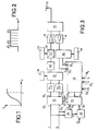
- Figure 1 is a diagram of operation of an amplifier 10 (figure 3) wherein it appears that, when the input signal S i becomes greater than a given value L, the output signal S o remains practically constant. This well known feature of an amplifier is called "saturation".
- the gain (the ratio S o /S i ) becomes non constant in amplitude and phase and this non constant behavior generates in band distortions of the output signal as well as out of band interferences which may be detrimental not only to the transmitted signal, but also to signals which may be transmitted simultaneously, at the same frequency or at different frequencies.
- the frequency band ⁇ F of the power amplifier is subdivided into domains or subbands ⁇ F 1 , ⁇ F 2 , ... ⁇ F n (figure 2) and the corresponding predistortion is provided for each subband.
- Figure 3 represents a base station comprising the above mentioned power amplifier 10 and also a coherent receiver chain 16.
- the output of amplifier 10 is connected to a transmitting/receiving antenna 18 through a coupler 20.
- the coupler is used also to connect the antenna 18 to the input of the receiver chain 16.
- the receiver chain is a dedicated chain used for the measurement of output signals of the amplifier in order to update tables or sets of coefficients as will be explained herein below.
- the signals to be amplified by power amplifier 10 are samples at a sample frequency of 32,768 megahertz. These samples are, classically, represented by their complex coordinates I and Q.
- the coordinates I and Q are applied to the respective inputs 22 1 and 22 2 of a complex multiplier accumulator (CMAC) 22, the function of which will be described later.
- CMAC complex multiplier accumulator
- These two coordinates I and Q, which represent the real time signal in rectangular coordinates are converted into polar coordinates by a Cordic converter 24.
- This converter 24 has two outputs 24 1 and 24 2 .
- the output 24 1 provides the amplitude R of the instantaneous input signal and the output 24 2 provides the phase ⁇ of the input sample.
- the R output 24 1 is connected to the amplitude input of a RAM memory containing look-up tables (LUT) and the output 24 2 of converter 24 is connected to the input of a differentiator 28 which operates at the sample frequency.
- the output 28 1 of this differentiator is connected to a frequency input 26 2 of the memory 26.
- the differentiator is a substractor which makes the difference between the phase of the present sample and the phase of the previous sample.
- the RAM memory 26 has also one input 26 3 connected to the output of a digital signal processor 30 which provides signals for updating the values in the tables memorized in RAM 26 as explained hereinafter.
- the RAM 26 has two outputs 26 4 , 26 5 which provide signals ⁇ l', ⁇ Q' applied to corresponding respective inputs of CMAC 22.
- These signals ⁇ l' and ⁇ Q' are predistortions of, respectively, I and Q which are applied to said coordinates in order to compensate for distortions due to non linearities.
- the complex multiplier/accumulator 22 has two digital outputs 22 3 and 22 4 on which appear the predistorted components I i and Q 1 of the input sampled signal. These digital components are connected to the respective inputs of a quadrature mixer 32 through, respectively, digital to analog (D/A) converters 34 3 and 34 4 .
- the role of this mixer 32 is, in connection with an intermediate frequency local oscillator 36, to convert the input signal, which is in base band frequency, into intermediate frequency.
- the output of mixer 32 is connected to the input of another mixer 38 through an intermediate frequency (IF) interface 40 including and IF filter having a band pass of at least 3 (for instance) times the useful channel, this band pass being preferably flat. In fact, if the band pass would correspond exactly to the useful channel, it would not be possible to linearize correctly outside of this channel.
- IF intermediate frequency
- the mixer 38 converts, with a second local oscillator 42, the IF into a signal modulated at the transmission frequency.
- the output of mixer 38 is connected to the input of power amplifier 10.
- receiver chain 16 is also connected to the input of a quadrature mixer 44 which, with a local oscillator 46, converts the received signal into analog I D and Q D components of the received signal. These components are in the base band frequency. These signals are applied to respective inputs 30 1 , 30 2 of processor 30 where they are converted into digital format.
- local oscillators 42 and 46 are synchronized.
- memory 26 are stored n tables, one for each frequency subband ⁇ F 1 ... ⁇ F n . The selection of the table is made according to the instantaneous frequency measured by differentiator 28.
- the memory 26 delivers signals ⁇ l' and ⁇ Q' which are combined to components I and Q to predistort the signals which will be provided on mixer 32 and, through mixer 38, on the input of power amplifier 10.
- a look-up table is a table of correspondence between the amplitude R of the input signal provided by output 24 1 of converter 24, and predistortion components ⁇ l' and ⁇ Q'. In other words, for each increment of amplitude R, ⁇ l' and ⁇ Q' may vary.
- a precalculated mathematical model of predistortions is established.
- processor 30 The role of processor 30 is to apply on input 26 3 of memory 26 updated values of each item of the tables (or of each coefficient in case of a polynomial model). In fact, it is necessary to update these values and coefficients at least from time to time, because of aging, temperature variations, variations of power voltages, etc.
- This updating is performed by a learning algorithm which is implemented in processor 30.
- Such learning algorithm being conventional, it is not necessary to describe it in details.
- test signals are injected at the input. These test signals are detected by the receiver chain 16,44 through the coupler 20 which provides on inputs 30 1 and 30 2 analog signals which are used to calculate the predistortion values of the tables, or the coefficients of the polynoms.
- the test signal comprises, for each frequency subband ⁇ F 1 , ⁇ F 2 , etc., two isolated frequencies and the extra spectral values which may appear on inputs 30 1 and 30 2 are used to calculate the predistortion values or coefficients.
- the learning or updating algorithm uses the normal signals applied to the amplifier. Therefore, it is not necessary to stop the operation of the base station for updating. Moreover, with such real time algorithm, it is possible to update more frequently the values or coefficients.
- the processor 30 needs inputs 30 3 and 30 4 for the I and Q values applied on the inputs of multiplier 22 and also an input 30 5 for the sample frequency as a reference signal.
- the usual base station receiver (not shown) may be used in order to check or measure the effect of test signals, or of normal signals, on the output of amplifier for calculating the predistortion values or coefficients, provided that, during this time, the receiver is tuned to the transmission band.
- the base station When the base station is provided with two receivers, which are normally used simultaneously (this is generally called uplink diversity), one of these receivers may be used also for the detection of test signals or normal signals and it provides signals at the input 30 1 , 30 2 of processor 30.
- This embodiment is particularly useful when the updating is performed during normal operation because, with the use of the second receiver, it is possible to minimize the effect of the updating on normal performances of the amplifier 10.
- the method and the device which have been described may be used for the linearisation of power amplifiers, the digital input signals being either in intermediate frequency or in base band frequency.
Landscapes
- Physics & Mathematics (AREA)
- Nonlinear Science (AREA)
- Engineering & Computer Science (AREA)
- Power Engineering (AREA)
- Amplifiers (AREA)
Priority Applications (4)
| Application Number | Priority Date | Filing Date | Title |
|---|---|---|---|
| DE69940998T DE69940998D1 (de) | 1999-06-30 | 1999-06-30 | Verfahren zur breitbandigen Linearisierung von Leistungsverstärkern |
| EP99401627A EP1067676B1 (fr) | 1999-06-30 | 1999-06-30 | Procédé de linéarisation en bande large d'amplificateurs de puissance |
| US09/429,026 US6885709B1 (en) | 1999-06-30 | 1999-10-29 | Method for linearising a power amplifier over a wide frequency band |
| CN00119924.2A CN1288835C (zh) | 1999-06-30 | 2000-06-30 | 用于在宽频带上线性化功率放大器的方法 |
Applications Claiming Priority (1)
| Application Number | Priority Date | Filing Date | Title |
|---|---|---|---|
| EP99401627A EP1067676B1 (fr) | 1999-06-30 | 1999-06-30 | Procédé de linéarisation en bande large d'amplificateurs de puissance |
Publications (2)
| Publication Number | Publication Date |
|---|---|
| EP1067676A1 true EP1067676A1 (fr) | 2001-01-10 |
| EP1067676B1 EP1067676B1 (fr) | 2009-06-17 |
Family
ID=8242035
Family Applications (1)
| Application Number | Title | Priority Date | Filing Date |
|---|---|---|---|
| EP99401627A Expired - Lifetime EP1067676B1 (fr) | 1999-06-30 | 1999-06-30 | Procédé de linéarisation en bande large d'amplificateurs de puissance |
Country Status (4)
| Country | Link |
|---|---|
| US (1) | US6885709B1 (fr) |
| EP (1) | EP1067676B1 (fr) |
| CN (1) | CN1288835C (fr) |
| DE (1) | DE69940998D1 (fr) |
Cited By (9)
| Publication number | Priority date | Publication date | Assignee | Title |
|---|---|---|---|---|
| WO2001061841A1 (fr) * | 2000-02-17 | 2001-08-23 | Wireless Systems International Limited | Detection de distorsion dans un amplificateur de puissance |
| WO2001099298A1 (fr) * | 2000-06-21 | 2001-12-27 | Central Research Laboratories Limited | Emetteur-recepteur a frequences radio (rf) |
| WO2001099439A3 (fr) * | 2000-06-22 | 2002-07-04 | Fujant Inc | Recuperation d'un signal de circuit de retour |
| WO2002103897A1 (fr) * | 2001-06-14 | 2002-12-27 | Telefonaktiebolaget Lm Ericsson | Predistortion au moyen d'un signal de derivation |
| GB2394374A (en) * | 2002-10-17 | 2004-04-21 | Roke Manor Research | An IQ feedback predistortion loop comprising a power amplifier (PA) and a PA model |
| WO2004070942A1 (fr) * | 2003-01-16 | 2004-08-19 | Siemens Aktiengesellschaft | Ensemble circuit pour retroaction de l'emetteur vers le recepteur dans un telephone mobile multimode a predistorsion |
| EP1465353A3 (fr) * | 2003-04-02 | 2005-03-02 | Samsung Electronics Co., Ltd. | Dispositif et procédé d'auto étalonnage dans un émetteur-récepteur mobile |
| EP1614224A4 (fr) * | 2003-04-16 | 2009-05-06 | Powerwave Technologies Inc | Systeme de predistorsion numerique additive faisant appel a la conversion de coordonnees de parcours paralleles |
| CN105305980A (zh) * | 2015-11-12 | 2016-02-03 | 电子科技大学 | 反馈式预失真线性化方法 |
Families Citing this family (17)
| Publication number | Priority date | Publication date | Assignee | Title |
|---|---|---|---|---|
| CN1124756C (zh) * | 2000-11-14 | 2003-10-15 | 华为技术有限公司 | 一种基于宽带多载波基站的增益均衡方法和装置 |
| US7248642B1 (en) | 2002-02-05 | 2007-07-24 | Andrew Corporation | Frequency-dependent phase pre-distortion for reducing spurious emissions in communication networks |
| US7266159B2 (en) | 2002-03-08 | 2007-09-04 | Andrew Corporation | Frequency-dependent magnitude pre-distortion on non-baseband input signals for reducing spurious emissions in communication networks |
| US7197085B1 (en) | 2002-03-08 | 2007-03-27 | Andrew Corporation | Frequency-dependent magnitude pre-distortion for reducing spurious emissions in communication networks |
| CN1177449C (zh) | 2002-04-23 | 2004-11-24 | 华为技术有限公司 | 基于基带数字预失真技术的提高射频功率放大器效率的方法 |
| US7139327B2 (en) * | 2002-06-10 | 2006-11-21 | Andrew Corporation | Digital pre-distortion of input signals for reducing spurious emissions in communication networks |
| JP2006526916A (ja) * | 2003-05-09 | 2006-11-24 | コーニンクレッカ フィリップス エレクトロニクス エヌ ヴィ | 移動体通信装置の送信電力を設定するための方法および装置 |
| US7251293B2 (en) * | 2003-06-27 | 2007-07-31 | Andrew Corporation | Digital pre-distortion for the linearization of power amplifiers with asymmetrical characteristics |
| US7129778B2 (en) * | 2003-07-23 | 2006-10-31 | Northrop Grumman Corporation | Digital cross cancellation system |
| US7280612B2 (en) * | 2003-07-25 | 2007-10-09 | Zarbana Digital Fund Llc | Digital branch calibrator for an RF transmitter |
| EP1560327B1 (fr) * | 2004-01-28 | 2006-06-07 | NTT DoCoMo, Inc. | Dispositif de prédistortion à bandes multiples avec tables de correspondance |
| US8503952B2 (en) * | 2008-04-10 | 2013-08-06 | Broadcom Corporation | Compensation of an asymmetric frequency response of a radio |
| DE102009031017B4 (de) * | 2009-06-29 | 2018-06-21 | Wobben Properties Gmbh | Verfahren und Vorrichtung zur Beobachtung eines dreiphasigen Wechselspannungsnetzes sowie Windenergieanlage |
| US8358170B2 (en) * | 2010-03-23 | 2013-01-22 | Intersil Americas Inc. | Power amplifier linearization using cancellation-based feed forward methods and systems |
| US8711976B2 (en) | 2011-05-12 | 2014-04-29 | Andrew Llc | Pre-distortion architecture for compensating non-linear effects |
| FR2991527B1 (fr) * | 2012-05-30 | 2014-06-27 | Centre Nat Etd Spatiales | Procede de calibration de lineariseur et composant electronique linearise |
| US9722644B2 (en) * | 2015-08-18 | 2017-08-01 | Nokia Solutions And Networks Oy | Frequency switching within time domain digital pre-distortion |
Citations (7)
| Publication number | Priority date | Publication date | Assignee | Title |
|---|---|---|---|---|
| US4604589A (en) * | 1984-01-19 | 1986-08-05 | The Marconi Company Limited | High frequency circuit |
| GB2245115A (en) * | 1987-04-28 | 1991-12-18 | Racal Communications Equip | Measuring distortion |
| EP0580125A1 (fr) * | 1992-07-21 | 1994-01-26 | Ortel Corporation | Dispositif de prédistortion pour la linéarisation de signaux électroniques et optiques |
| US5424680A (en) * | 1993-11-30 | 1995-06-13 | Harmonic Lightwaves, Inc. | Predistorter for high frequency optical communications devices |
| US5455538A (en) * | 1993-06-30 | 1995-10-03 | Fujitsu Limited | Linear amplifier for amplifying a composite signal of plural frequency components |
| US5535246A (en) * | 1991-06-04 | 1996-07-09 | National Transcommunications Limited | Method of video noise reduction using non-linear pre/de-emphasis |
| EP0774833A1 (fr) * | 1995-11-16 | 1997-05-21 | Ntt Mobile Communications Network Inc. | Dispositif amplificateur |
Family Cites Families (15)
| Publication number | Priority date | Publication date | Assignee | Title |
|---|---|---|---|---|
| US5334946A (en) * | 1990-04-25 | 1994-08-02 | British Technology Group Limited | Apparatus and method for reducing distortion in amplification |
| GB2257860B (en) * | 1991-07-06 | 1995-09-20 | Racal Communications Syst Ltd | Amplification systems |
| IT1265271B1 (it) * | 1993-12-14 | 1996-10-31 | Alcatel Italia | Sistema di predistorsione in banda base per la linearizzazione adattativa di amplificatori di potenza |
| US6157811A (en) * | 1994-01-11 | 2000-12-05 | Ericsson Inc. | Cellular/satellite communications system with improved frequency re-use |
| US5489879A (en) * | 1995-02-16 | 1996-02-06 | Seiko Communication Systems, Inc. | Amplitude and phase error normalization of subcarrier generator |
| US5991308A (en) * | 1995-08-25 | 1999-11-23 | Terayon Communication Systems, Inc. | Lower overhead method for data transmission using ATM and SCDMA over hybrid fiber coax cable plant |
| US5900778A (en) * | 1997-05-08 | 1999-05-04 | Stonick; John T. | Adaptive parametric signal predistorter for compensation of time varying linear and nonlinear amplifier distortion |
| US6075411A (en) * | 1997-12-22 | 2000-06-13 | Telefonaktiebolaget Lm Ericsson | Method and apparatus for wideband predistortion linearization |
| US5886573A (en) * | 1998-03-06 | 1999-03-23 | Fujant, Inc. | Amplification using amplitude reconstruction of amplitude and/or angle modulated carrier |
| US6600792B2 (en) * | 1998-06-26 | 2003-07-29 | Qualcomm Incorporated | Predistortion technique for high power amplifiers |
| US6240278B1 (en) * | 1998-07-30 | 2001-05-29 | Motorola, Inc. | Scalar cost function based predistortion linearizing device, method, phone and basestation |
| US6493543B1 (en) * | 1998-10-19 | 2002-12-10 | Powerwave Technologies, Inc. | Multichannel amplification system using mask detection |
| US6542562B1 (en) * | 1999-02-09 | 2003-04-01 | Telefonaktiebolaget Lm Ericsson (Publ) | Approximated MMSE-based channel estimator in a mobile communication system |
| US6590940B1 (en) * | 1999-05-17 | 2003-07-08 | Ericsson Inc. | Power modulation systems and methods that separately amplify low and high frequency portions of an amplitude waveform |
| US6609008B1 (en) * | 2000-11-09 | 2003-08-19 | Qualcomm Incoporated | Method and apparatus for controlling signal power level in a communication system |
-
1999
- 1999-06-30 EP EP99401627A patent/EP1067676B1/fr not_active Expired - Lifetime
- 1999-06-30 DE DE69940998T patent/DE69940998D1/de not_active Expired - Fee Related
- 1999-10-29 US US09/429,026 patent/US6885709B1/en not_active Expired - Fee Related
-
2000
- 2000-06-30 CN CN00119924.2A patent/CN1288835C/zh not_active Expired - Fee Related
Patent Citations (7)
| Publication number | Priority date | Publication date | Assignee | Title |
|---|---|---|---|---|
| US4604589A (en) * | 1984-01-19 | 1986-08-05 | The Marconi Company Limited | High frequency circuit |
| GB2245115A (en) * | 1987-04-28 | 1991-12-18 | Racal Communications Equip | Measuring distortion |
| US5535246A (en) * | 1991-06-04 | 1996-07-09 | National Transcommunications Limited | Method of video noise reduction using non-linear pre/de-emphasis |
| EP0580125A1 (fr) * | 1992-07-21 | 1994-01-26 | Ortel Corporation | Dispositif de prédistortion pour la linéarisation de signaux électroniques et optiques |
| US5455538A (en) * | 1993-06-30 | 1995-10-03 | Fujitsu Limited | Linear amplifier for amplifying a composite signal of plural frequency components |
| US5424680A (en) * | 1993-11-30 | 1995-06-13 | Harmonic Lightwaves, Inc. | Predistorter for high frequency optical communications devices |
| EP0774833A1 (fr) * | 1995-11-16 | 1997-05-21 | Ntt Mobile Communications Network Inc. | Dispositif amplificateur |
Cited By (14)
| Publication number | Priority date | Publication date | Assignee | Title |
|---|---|---|---|---|
| WO2001061841A1 (fr) * | 2000-02-17 | 2001-08-23 | Wireless Systems International Limited | Detection de distorsion dans un amplificateur de puissance |
| US6949975B2 (en) | 2000-02-17 | 2005-09-27 | Andrew Corporation | Distortion detection for a power amplifier |
| WO2001099298A1 (fr) * | 2000-06-21 | 2001-12-27 | Central Research Laboratories Limited | Emetteur-recepteur a frequences radio (rf) |
| WO2001099439A3 (fr) * | 2000-06-22 | 2002-07-04 | Fujant Inc | Recuperation d'un signal de circuit de retour |
| WO2002103897A1 (fr) * | 2001-06-14 | 2002-12-27 | Telefonaktiebolaget Lm Ericsson | Predistortion au moyen d'un signal de derivation |
| US7505530B2 (en) | 2001-06-14 | 2009-03-17 | Telefonaktiebolaget Lm Ericsson (Publ) | Pre-distortion using a by-pass signal |
| GB2394374A (en) * | 2002-10-17 | 2004-04-21 | Roke Manor Research | An IQ feedback predistortion loop comprising a power amplifier (PA) and a PA model |
| GB2394374B (en) * | 2002-10-17 | 2006-06-14 | Roke Manor Research | Improvements in or relating to RF transmitters |
| US7190932B2 (en) | 2003-01-16 | 2007-03-13 | Siemens Aktiengesellschaft | Circuit arrangement for a predistorted feedback coupling from a transmitter to a receiver in a multi-mode mobile telephone |
| WO2004070942A1 (fr) * | 2003-01-16 | 2004-08-19 | Siemens Aktiengesellschaft | Ensemble circuit pour retroaction de l'emetteur vers le recepteur dans un telephone mobile multimode a predistorsion |
| EP1465353A3 (fr) * | 2003-04-02 | 2005-03-02 | Samsung Electronics Co., Ltd. | Dispositif et procédé d'auto étalonnage dans un émetteur-récepteur mobile |
| US7130589B2 (en) | 2003-04-02 | 2006-10-31 | Sansung Electronics Co., Ltd. | Self-calibrating apparatus and method in a mobile transceiver |
| EP1614224A4 (fr) * | 2003-04-16 | 2009-05-06 | Powerwave Technologies Inc | Systeme de predistorsion numerique additive faisant appel a la conversion de coordonnees de parcours paralleles |
| CN105305980A (zh) * | 2015-11-12 | 2016-02-03 | 电子科技大学 | 反馈式预失真线性化方法 |
Also Published As
| Publication number | Publication date |
|---|---|
| CN1291000A (zh) | 2001-04-11 |
| CN1288835C (zh) | 2006-12-06 |
| US6885709B1 (en) | 2005-04-26 |
| EP1067676B1 (fr) | 2009-06-17 |
| DE69940998D1 (de) | 2009-07-30 |
Similar Documents
| Publication | Publication Date | Title |
|---|---|---|
| EP1067676B1 (fr) | Procédé de linéarisation en bande large d'amplificateurs de puissance | |
| KR101107866B1 (ko) | 무상관 적응 전치 보상기 | |
| US8594232B2 (en) | System for predistortion and post-distortion correction of both a receiver and transmitter during calibration | |
| US8126036B2 (en) | Predistortion and post-distortion correction of both a receiver and transmitter during calibration | |
| JP3381689B2 (ja) | 非線形歪み補償回路及びそれを用いた送信装置並びに移動通信機 | |
| US6614854B1 (en) | System and method for adaptive predistortion | |
| US5937011A (en) | Multi-carrier high power amplifier using digital pre-distortion | |
| KR100739356B1 (ko) | 무선 통신 시스템에서 인접 채널 파워를 감소시키는 방법및 장치 | |
| US6307435B1 (en) | High power amplifier linearization method using modified linear-log model predistortion | |
| US7415250B2 (en) | Distortion compensating amplifier | |
| US20140286360A1 (en) | Method and system for transmitting signals with reduced spurious emissions | |
| EP1313278A1 (fr) | Procede et appareil de predistorsion numerique auto-adaptatif d'un emetteur sans fil | |
| US20020027473A1 (en) | Distortion compensating device and distortion compensating method | |
| US6429740B1 (en) | High power amplifier linearization method using extended saleh model predistortion | |
| JP2001274646A (ja) | 自動利得制御装置 | |
| US7529524B1 (en) | Adaptive power amplifier linearization in time division duplex communication systems | |
| US6392482B1 (en) | Method for linearizing, over a wide frequency band a transmission chain comprising a power amplifier | |
| CA2069476C (fr) | Dispositif et methode pour faire varier un signal dans un emetteur ou un emetteur-recepteur | |
| US6954621B2 (en) | Method of and apparatus for predistorting a transmit signal | |
| US7209715B2 (en) | Power amplifying method, power amplifier, and communication apparatus | |
| JP6470397B2 (ja) | 包絡線追跡のためのタイミングアライメント感度 | |
| US6959174B2 (en) | Amplifying device | |
| KR100700102B1 (ko) | 디지털 트랜시버의 일정한 par 유지방법 | |
| US20240429883A1 (en) | Interpolated power tracking and input power adjustment based on peak-to-average power ratio | |
| Safari et al. | Block based predistortion for amplifier linearization in burst type mobile satellite communications |
Legal Events
| Date | Code | Title | Description |
|---|---|---|---|
| PUAI | Public reference made under article 153(3) epc to a published international application that has entered the european phase |
Free format text: ORIGINAL CODE: 0009012 |
|
| 17P | Request for examination filed |
Effective date: 19990713 |
|
| AK | Designated contracting states |
Kind code of ref document: A1 Designated state(s): DE ES FR GB IT |
|
| AX | Request for extension of the european patent |
Free format text: AL;LT;LV;MK;RO;SI |
|
| 17Q | First examination report despatched |
Effective date: 20010420 |
|
| AKX | Designation fees paid |
Free format text: DE ES FR GB IT |
|
| APAB | Appeal dossier modified |
Free format text: ORIGINAL CODE: EPIDOS NOAPE |
|
| APAB | Appeal dossier modified |
Free format text: ORIGINAL CODE: EPIDOS NOAPE |
|
| APAD | Appeal reference recorded |
Free format text: ORIGINAL CODE: EPIDOS REFNE |
|
| APBT | Appeal procedure closed |
Free format text: ORIGINAL CODE: EPIDOSNNOA9E |
|
| APAF | Appeal reference modified |
Free format text: ORIGINAL CODE: EPIDOSCREFNE |
|
| RAP1 | Party data changed (applicant data changed or rights of an application transferred) |
Owner name: ALCATEL LUCENT |
|
| GRAJ | Information related to disapproval of communication of intention to grant by the applicant or resumption of examination proceedings by the epo deleted |
Free format text: ORIGINAL CODE: EPIDOSDIGR1 |
|
| GRAP | Despatch of communication of intention to grant a patent |
Free format text: ORIGINAL CODE: EPIDOSNIGR1 |
|
| GRAS | Grant fee paid |
Free format text: ORIGINAL CODE: EPIDOSNIGR3 |
|
| GRAA | (expected) grant |
Free format text: ORIGINAL CODE: 0009210 |
|
| AK | Designated contracting states |
Kind code of ref document: B1 Designated state(s): DE ES FR GB IT |
|
| REG | Reference to a national code |
Ref country code: GB Ref legal event code: FG4D |
|
| REF | Corresponds to: |
Ref document number: 69940998 Country of ref document: DE Date of ref document: 20090730 Kind code of ref document: P |
|
| PGFP | Annual fee paid to national office [announced via postgrant information from national office to epo] |
Ref country code: FR Payment date: 20090716 Year of fee payment: 11 |
|
| PGFP | Annual fee paid to national office [announced via postgrant information from national office to epo] |
Ref country code: GB Payment date: 20090720 Year of fee payment: 11 |
|
| PG25 | Lapsed in a contracting state [announced via postgrant information from national office to epo] |
Ref country code: ES Free format text: LAPSE BECAUSE OF FAILURE TO SUBMIT A TRANSLATION OF THE DESCRIPTION OR TO PAY THE FEE WITHIN THE PRESCRIBED TIME-LIMIT Effective date: 20090928 |
|
| PLBE | No opposition filed within time limit |
Free format text: ORIGINAL CODE: 0009261 |
|
| STAA | Information on the status of an ep patent application or granted ep patent |
Free format text: STATUS: NO OPPOSITION FILED WITHIN TIME LIMIT |
|
| 26N | No opposition filed |
Effective date: 20100318 |
|
| PGFP | Annual fee paid to national office [announced via postgrant information from national office to epo] |
Ref country code: DE Payment date: 20091231 Year of fee payment: 11 |
|
| GBPC | Gb: european patent ceased through non-payment of renewal fee |
Effective date: 20100630 |
|
| REG | Reference to a national code |
Ref country code: FR Ref legal event code: ST Effective date: 20110228 |
|
| PG25 | Lapsed in a contracting state [announced via postgrant information from national office to epo] |
Ref country code: IT Free format text: LAPSE BECAUSE OF FAILURE TO SUBMIT A TRANSLATION OF THE DESCRIPTION OR TO PAY THE FEE WITHIN THE PRESCRIBED TIME-LIMIT Effective date: 20090617 |
|
| PG25 | Lapsed in a contracting state [announced via postgrant information from national office to epo] |
Ref country code: DE Free format text: LAPSE BECAUSE OF NON-PAYMENT OF DUE FEES Effective date: 20110101 |
|
| PG25 | Lapsed in a contracting state [announced via postgrant information from national office to epo] |
Ref country code: FR Free format text: LAPSE BECAUSE OF NON-PAYMENT OF DUE FEES Effective date: 20100630 |
|
| PG25 | Lapsed in a contracting state [announced via postgrant information from national office to epo] |
Ref country code: GB Free format text: LAPSE BECAUSE OF NON-PAYMENT OF DUE FEES Effective date: 20100630 |
|
| REG | Reference to a national code |
Ref country code: FR Ref legal event code: CA Effective date: 20150521 |
|
| REG | Reference to a national code |
Ref country code: FR Ref legal event code: CA Effective date: 20150521 |