EP1067821A2 - Prothèse auditive - Google Patents
Prothèse auditive Download PDFInfo
- Publication number
- EP1067821A2 EP1067821A2 EP00810584A EP00810584A EP1067821A2 EP 1067821 A2 EP1067821 A2 EP 1067821A2 EP 00810584 A EP00810584 A EP 00810584A EP 00810584 A EP00810584 A EP 00810584A EP 1067821 A2 EP1067821 A2 EP 1067821A2
- Authority
- EP
- European Patent Office
- Prior art keywords
- signal
- frequency
- path
- input signal
- attenuation
- Prior art date
- Legal status (The legal status is an assumption and is not a legal conclusion. Google has not performed a legal analysis and makes no representation as to the accuracy of the status listed.)
- Ceased
Links
Images
Classifications
-
- H—ELECTRICITY
- H04—ELECTRIC COMMUNICATION TECHNIQUE
- H04R—LOUDSPEAKERS, MICROPHONES, GRAMOPHONE PICK-UPS OR LIKE ACOUSTIC ELECTROMECHANICAL TRANSDUCERS; ELECTRIC HEARING AIDS; PUBLIC ADDRESS SYSTEMS
- H04R25/00—Electric hearing aids
- H04R25/50—Customised settings for obtaining desired overall acoustical characteristics
- H04R25/502—Customised settings for obtaining desired overall acoustical characteristics using analog signal processing
-
- H—ELECTRICITY
- H04—ELECTRIC COMMUNICATION TECHNIQUE
- H04R—LOUDSPEAKERS, MICROPHONES, GRAMOPHONE PICK-UPS OR LIKE ACOUSTIC ELECTROMECHANICAL TRANSDUCERS; ELECTRIC HEARING AIDS; PUBLIC ADDRESS SYSTEMS
- H04R2225/00—Details of deaf aids covered by H04R25/00, not provided for in any of its subgroups
- H04R2225/43—Signal processing in hearing aids to enhance the speech intelligibility
Definitions
- the invention relates to a device, in particular an electronic circuit, and a method for suppressing interference signals in an input signal according to the preambles of the independent claims.
- the invention is suitable in particular to improve speech intelligibility through suppression of noise from hearing aids or hearing aids.
- an apparatus and a method for Interference noise suppression specify which speech intelligibility is objective improve and also only a slight delay (e.g. less than 2 ms) have between input and output signal.
- the task is solved by the circuit according to the invention and the method according to the invention as described in the independent claims are defined.
- the starting point for the invention is the American National Standard Document ANSI S3.5-1997, "Methods for the Calculation of the Speech Intelligibility Index ". According to this standard, it can be used for sufficiently defined Listening situations, calculate a numerical index value S, the real values between assumes zero and one. It provides information about the proportion of the in Spoken language features included overall for speech intelligibility in the given situation to a listener for the understanding process in the brain are accessible. For the concrete results of a language test are still the Degree of difficulty of the language material as well as the language competence of the listener significant. The key point, however, is that the test result is in in any case proves to be a monotonically increasing function of the index value S.
- the standard font presents different variants for calculating the index value S, which differ mainly in the number of frequency bands in which speech and noise signals are analyzed.
- the minimum is six bands and the maximum is 21.
- a variable A i for the audibility is determined for each frequency band i, and the index results as a weighted sum where I i denote constant, relative importance weights (importance) for the individual subbands, ie the sum of all these weights is one.
- the variables D i result as a level of a fictitious noise, which is generally determined by the hearing threshold values of normal hearing or in a special case by those of the individual hearing impaired.
- the variables D i are determined by the external noise, in addition to any masking effects, which are also caused by the noise, but by its proportions in bands of lower frequency.
- the speech levels in formula (4) can be raised above the hearing threshold values D i of a hearing impaired person by means of amplification in a hearing aid and thus the temporary variables K i can be maximized, the situation in noise is far less favorable.
- the amplification increases the levels of the speech signal and the noise to the same extent, and as soon as the latter exceed the hearing threshold values of the hearing impaired, they are decisive for the variables D i , and any further increase in the temporary variables K i is consequently impossible.
- the level values E i are generally significantly above those of normal language U i under these circumstances. This means that the prerequisites for increasing the index value S are also given in noise, by reducing the amplification, as long as the distortion quantities L i approach the ideal value 1 and at the same time the temporary variables K i remain constant. Another desirable effect also results from the reduction of masking effects if the noise has significant proportions at low frequencies, which is often the case in practice.
- the device in particular an electronic circuit for Suppression of interference signals in an input signal includes means for frequency-dependent attenuation of signal components. It shows one Main signal path with means for frequency-dependent attenuation of Signal components in the input signal, an output signal of these means is the output signal of the circuit for frequency-dependent attenuation. It also has a signal analysis path parallel to the main signal path Means for the periodic calculation of frequency-dependent Attenuation factors from the input signal. So in the main signal path neither a transformation into the frequency range nor a division into Subband signals made; the main signal path preferably only points a suppression filter.
- the signal analysis path is like that with Main signal path connected that the attenuation factors provide the means for frequency-dependent attenuation are available.
- the hearing aid according to the invention contains the device according to the invention.
- the inventive method for suppressing interference signals in one Input signal signal components are attenuated depending on the frequency.
- the Input signal is in a main signal path and in a parallel to the Main signal path divided signal analysis path.
- the main signal path is the output signal of the circuit is generated by signal components are weakened depending on frequency; so there will be neither Transformation into the frequency domain still a division into subband signals Frequency-dependent are made in the signal analysis path
- Attenuation factors are calculated periodically from the input signal. The Attenuation factors are used for frequency-dependent attenuation used.
- the invention allows an analysis of the input signal in a sufficient number and enough sharply separated frequency bands without doing an undue To cause signal delay. At the same time, it enables efficient Implementation with moderate computing power.
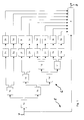
- the method according to the invention divides the input signal into an input 7 a main signal path 5 with a suppression transversal filter 4 and one parallel signal analysis path 6 with a block 1a-1g, 2a-2h, 3a-3h for the Signal analysis on.
- the signal analysis takes place in Embodiment in eight different frequency bands.
- the outputs of the units 3a to 3h are periodically provided by the signal analysis Embodiment every 32 ms - that for the different frequency bands calculated values of the required gain reduction are available.
- the transversal filter 4 subsequently sets the current one for suppression the noise function required together.
- this filter 4 is a linear-phase filter Transversal filter with 48 coefficients, which at a sampling rate of 16 kHz Delay of 1.5 ms causes.
- this fact is intended for the In general, however, suppression of continuous noise insignificant. The only exception is the beginning of a speech signal a longer pause in the noise. In this case, during the Speech break took place gain reductions in the frequency bands in which the Dominate language levels, be withdrawn quickly. For that very purpose In units 3a to 3h special precautions are built in, which are later Place in this description will be explained in more detail.
- a half-band transversal filter thus comprises a low pass filter and a high pass filter at the same time.
- sample values at the input of a half-band transversal filter are designated with x [n]
- sample values y TP [n] result at the output of the low-pass filter in accordance with
- each of the two output signals of a half-band transversal filter 1a to 1g only has half the bandwidth of the input signal. Consequently, the sampling rate of the output signals can be reduced to half without loss of information, ie only every second output value is required for further processing. Of course, samples of output signals that are no longer required subsequently need not be calculated at all.
- the calculation formulas (8) and (9) only have to be carried out in every second sampling interval. For the arrangement of the half-band transversal filters 1a to 1g in the exemplary embodiment, this results in processing in sixteen different, successive phases. Table II below shows the filters for which the calculation formulas must be carried out in each phase.
- Another advantage is the selectivity between neighboring ones Frequency bands. With the successive reduction of the sampling rate, the filters show narrower bandwidth also increasingly steeper flanks.
- units 2a to 2h in FIG. 1 are used to calculate power values of short signal segments which are required for further processing in the logarithmic range, i.e. in decibels.
- the duration of these time segments is 32 ms.
- units 3a to 3h are used to calculate how much gain reduction is to be applied in the different frequency bands.
- new logarithmic estimated values p arrive at the input of these computing units 3a to 3h every 32 ms.
- the range of variation r of the signal powers in the individual partial signals is to be determined over the immediately past period of time.
- the variation range in a partial signal is below 15 dB, the gain in the corresponding frequency band is reduced by the difference of 15 dB. If the signal level remains constant for a long time, the value for the variation range is 0 dB and consequently a maximum gain reduction of 15 dB.
- the time course of the variable r is determined by the quantities ⁇ and ⁇ determined, and by applying the third power to the expression in parentheses in formula (13), which records the difference from the previous value of r.
- the Processing steps of formulas (11) to (14) bring about in a simple manner asymmetrical temporal behavior that ideally meets the practical requirements Way corresponds.
- random little differences in successive values of the signal power have practically no effect on the Estimate r.
- a decrease in the range of variation r can occur according to the associated gain reduction AG only over a period of time of a few seconds.
- an abrupt increase in Signal power to a significant extent, e.g. B. by 40 dB that a Gain reduction of up to 12 dB from one time segment to the next is completely canceled.
- the coefficients of a transversal filter also represent at the same time represents his impulse response. This also applies to the suppression transversal filter 4 as well as for the transverse bandpass filters according to formula (18). Under this From the point of view, the formula (16) means that the impulse response of the Suppression transversal filter 4 periodically as a weighted sum of Transverse bandpass filter impulse responses are recalculated.
Landscapes
- Health & Medical Sciences (AREA)
- General Health & Medical Sciences (AREA)
- Neurosurgery (AREA)
- Otolaryngology (AREA)
- Physics & Mathematics (AREA)
- Engineering & Computer Science (AREA)
- Acoustics & Sound (AREA)
- Signal Processing (AREA)
- Noise Elimination (AREA)
- Filters That Use Time-Delay Elements (AREA)
- Cable Transmission Systems, Equalization Of Radio And Reduction Of Echo (AREA)
Applications Claiming Priority (2)
| Application Number | Priority Date | Filing Date | Title |
|---|---|---|---|
| CH125699 | 1999-07-08 | ||
| CH125699 | 1999-07-08 |
Publications (2)
| Publication Number | Publication Date |
|---|---|
| EP1067821A2 true EP1067821A2 (fr) | 2001-01-10 |
| EP1067821A3 EP1067821A3 (fr) | 2008-04-30 |
Family
ID=4206139
Family Applications (1)
| Application Number | Title | Priority Date | Filing Date |
|---|---|---|---|
| EP00810584A Ceased EP1067821A3 (fr) | 1999-07-08 | 2000-07-05 | Prothèse auditive |
Country Status (3)
| Country | Link |
|---|---|
| US (1) | US6580798B1 (fr) |
| EP (1) | EP1067821A3 (fr) |
| AU (1) | AU771005B2 (fr) |
Cited By (1)
| Publication number | Priority date | Publication date | Assignee | Title |
|---|---|---|---|---|
| EP1453355A1 (fr) * | 2003-02-26 | 2004-09-01 | Bernafon AG | Traitement de signal dans un appareil auditif |
Families Citing this family (4)
| Publication number | Priority date | Publication date | Assignee | Title |
|---|---|---|---|---|
| CN100565672C (zh) * | 2005-12-30 | 2009-12-02 | 财团法人工业技术研究院 | 去除语音信号中背景噪声的方法 |
| WO2011137933A1 (fr) * | 2010-05-06 | 2011-11-10 | Phonak Ag | Procédé d'utilisation d'un dispositif d'écoute et dispositif d'écoute |
| US9854358B2 (en) * | 2014-07-25 | 2017-12-26 | 2236008 Ontario Inc. | System and method for mitigating audio feedback |
| DE102015204253B4 (de) | 2015-03-10 | 2016-11-10 | Sivantos Pte. Ltd. | Verfahren zur frequenzabhängigen Rauschunterdrückung eines Eingangssignals sowie Hörgerät |
Family Cites Families (4)
| Publication number | Priority date | Publication date | Assignee | Title |
|---|---|---|---|---|
| US4630304A (en) * | 1985-07-01 | 1986-12-16 | Motorola, Inc. | Automatic background noise estimator for a noise suppression system |
| US5029217A (en) * | 1986-01-21 | 1991-07-02 | Harold Antin | Digital hearing enhancement apparatus |
| US5027410A (en) * | 1988-11-10 | 1991-06-25 | Wisconsin Alumni Research Foundation | Adaptive, programmable signal processing and filtering for hearing aids |
| JP2970498B2 (ja) * | 1995-10-26 | 1999-11-02 | 日本電気株式会社 | ディジタル補聴器 |
-
2000
- 2000-07-05 AU AU45083/00A patent/AU771005B2/en not_active Ceased
- 2000-07-05 EP EP00810584A patent/EP1067821A3/fr not_active Ceased
- 2000-07-10 US US09/612,849 patent/US6580798B1/en not_active Expired - Lifetime
Non-Patent Citations (1)
| Title |
|---|
| None * |
Cited By (2)
| Publication number | Priority date | Publication date | Assignee | Title |
|---|---|---|---|---|
| EP1453355A1 (fr) * | 2003-02-26 | 2004-09-01 | Bernafon AG | Traitement de signal dans un appareil auditif |
| AU2004200726B2 (en) * | 2003-02-26 | 2008-12-11 | Bernafon Ag | Signal processing in a hearing aid |
Also Published As
| Publication number | Publication date |
|---|---|
| AU4508300A (en) | 2001-01-11 |
| EP1067821A3 (fr) | 2008-04-30 |
| AU771005B2 (en) | 2004-03-11 |
| US6580798B1 (en) | 2003-06-17 |
Similar Documents
| Publication | Publication Date | Title |
|---|---|---|
| EP1005695B1 (fr) | Procede et dispositif permettant de detecter un transitoire dans un signal audio discontinu, et dispositif et procede de codage d'un signal audio | |
| DE69313480T2 (de) | Rauschverminderungseinrichtung | |
| DE69428119T2 (de) | Verringerung des hintergrundrauschens zur sprachverbesserung | |
| EP0624866B1 (fr) | Procédé d'analyse de fréquence | |
| DE69319494T2 (de) | Kodierungsvorrichtung für Audiosignalen und Verfahren dazu | |
| DE602005006331T2 (de) | Schallquellensignal-Trennvorrichtung und-Trennverfahren | |
| EP1853089B1 (fr) | Méthode pour la suppression de la rétroaction et pour l'éxpansion spéctrale pour des appareils de correction auditive | |
| DE2207141C3 (de) | Schaltungsanordnung zur Unterdrückung unerwünschter Sprachsignale mittels eines vorhersagenden Filters | |
| DE102006047197B3 (de) | Vorrichtung und Verfahren zum Verarbeiten eines reellen Subband-Signals zur Reduktion von Aliasing-Effekten | |
| EP3197181B1 (fr) | Procédé de réduction du temps de latence d'un banc de filtrage destiné au filtrage d'un signal audio et procédé de fonctionnement sans latence d'un système auditif | |
| DE19647399C1 (de) | Gehörangepaßte Qualitätsbeurteilung von Audiotestsignalen | |
| EP0641143A2 (fr) | Procédé pour simuler un effet spatial et/ou sonore | |
| EP3089481B1 (fr) | Procédé de suppression du bruit d'un signal d'entrée en fonction de la fréquence | |
| EP1155561B1 (fr) | Dispositif et procede de suppression de bruit dans des installations telephoniques | |
| EP1239455A2 (fr) | Méthode et dispositif pour la réalisation d'une transformation de Fourier adaptée à la fonction de transfert des organes sensoriels humains, et dispositifs pour la réduction de bruit et la reconnaissance de parole basés sur ces principes | |
| EP0777326B1 (fr) | Procédé et appareil pour le filtrage d'un signal audio | |
| DE60304147T2 (de) | Virtuelle Mikrophonanordnung | |
| EP1453355B1 (fr) | Traitement de signal dans un appareil auditif | |
| EP1067821A2 (fr) | Prothèse auditive | |
| EP1458216B1 (fr) | Appareil et procédé à l'adaption de microphones dans une prothèse auditive | |
| DE10250361A1 (de) | Vorrichtung und Verfahren zur Aufbereitung von Pilotsymbolen für eine Kanalschätzung mittels adaptiver Tiefpassfilterung | |
| DE102024108243B4 (de) | Verfahren zur Verarbeitung von Audiosignalen | |
| EP1755110A2 (fr) | Procédé et dispositif destinés à la réduction adaptative de signaux de bruit et de fond dans un système de traitement vocal | |
| DE3806416C2 (fr) | ||
| EP1433295B1 (fr) | Procede permettant de verifier la presence d'une composante de signal et dispositif servant a mettre en oeuvre ce procede |
Legal Events
| Date | Code | Title | Description |
|---|---|---|---|
| PUAI | Public reference made under article 153(3) epc to a published international application that has entered the european phase |
Free format text: ORIGINAL CODE: 0009012 |
|
| AK | Designated contracting states |
Kind code of ref document: A2 Designated state(s): AT BE CH CY DE DK ES FI FR GB GR IE IT LI LU MC NL PT SE |
|
| AX | Request for extension of the european patent |
Free format text: AL;LT;LV;MK;RO;SI |
|
| PUAL | Search report despatched |
Free format text: ORIGINAL CODE: 0009013 |
|
| AK | Designated contracting states |
Kind code of ref document: A3 Designated state(s): AT BE CH CY DE DK ES FI FR GB GR IE IT LI LU MC NL PT SE |
|
| AX | Request for extension of the european patent |
Extension state: AL LT LV MK RO SI |
|
| 17P | Request for examination filed |
Effective date: 20081021 |
|
| AKX | Designation fees paid |
Designated state(s): CH DE DK FR GB LI |
|
| 17Q | First examination report despatched |
Effective date: 20090731 |
|
| STAA | Information on the status of an ep patent application or granted ep patent |
Free format text: STATUS: THE APPLICATION HAS BEEN REFUSED |
|
| 18R | Application refused |
Effective date: 20180926 |