EP1068484B1 - Systeme de securite pour amorce de projectile - Google Patents
Systeme de securite pour amorce de projectile Download PDFInfo
- Publication number
- EP1068484B1 EP1068484B1 EP99914666A EP99914666A EP1068484B1 EP 1068484 B1 EP1068484 B1 EP 1068484B1 EP 99914666 A EP99914666 A EP 99914666A EP 99914666 A EP99914666 A EP 99914666A EP 1068484 B1 EP1068484 B1 EP 1068484B1
- Authority
- EP
- European Patent Office
- Prior art keywords
- initiator
- projectile
- firing pin
- safety
- firing
- Prior art date
- Legal status (The legal status is an assumption and is not a legal conclusion. Google has not performed a legal analysis and makes no representation as to the accuracy of the status listed.)
- Expired - Lifetime
Links
- 238000010304 firing Methods 0.000 claims abstract description 142
- 239000003999 initiator Substances 0.000 claims abstract description 96
- 239000002360 explosive Substances 0.000 claims abstract description 28
- 230000000977 initiatory effect Effects 0.000 claims abstract description 12
- 230000006835 compression Effects 0.000 claims description 17
- 238000007906 compression Methods 0.000 claims description 17
- 230000001133 acceleration Effects 0.000 claims description 16
- 230000003019 stabilising effect Effects 0.000 claims description 15
- 230000000452 restraining effect Effects 0.000 claims description 11
- 230000004044 response Effects 0.000 claims description 5
- 230000000717 retained effect Effects 0.000 abstract description 11
- 230000007246 mechanism Effects 0.000 abstract description 4
- 239000000463 material Substances 0.000 description 9
- 239000000853 adhesive Substances 0.000 description 8
- 230000001070 adhesive effect Effects 0.000 description 8
- 239000003380 propellant Substances 0.000 description 5
- 239000004411 aluminium Substances 0.000 description 4
- 229910052782 aluminium Inorganic materials 0.000 description 4
- XAGFODPZIPBFFR-UHFFFAOYSA-N aluminium Chemical compound [Al] XAGFODPZIPBFFR-UHFFFAOYSA-N 0.000 description 4
- 238000005266 casting Methods 0.000 description 4
- RTAQQCXQSZGOHL-UHFFFAOYSA-N Titanium Chemical compound [Ti] RTAQQCXQSZGOHL-UHFFFAOYSA-N 0.000 description 2
- 230000008901 benefit Effects 0.000 description 2
- 238000010276 construction Methods 0.000 description 2
- 238000005474 detonation Methods 0.000 description 2
- 230000000694 effects Effects 0.000 description 2
- 238000004519 manufacturing process Methods 0.000 description 2
- 238000007493 shaping process Methods 0.000 description 2
- 239000000126 substance Substances 0.000 description 2
- 230000001960 triggered effect Effects 0.000 description 2
- RYGMFSIKBFXOCR-UHFFFAOYSA-N Copper Chemical compound [Cu] RYGMFSIKBFXOCR-UHFFFAOYSA-N 0.000 description 1
- 230000004308 accommodation Effects 0.000 description 1
- 230000009471 action Effects 0.000 description 1
- 238000002144 chemical decomposition reaction Methods 0.000 description 1
- 238000004891 communication Methods 0.000 description 1
- 230000009514 concussion Effects 0.000 description 1
- 239000010949 copper Substances 0.000 description 1
- 229910052802 copper Inorganic materials 0.000 description 1
- 230000002950 deficient Effects 0.000 description 1
- 239000003822 epoxy resin Substances 0.000 description 1
- 238000004880 explosion Methods 0.000 description 1
- 238000013467 fragmentation Methods 0.000 description 1
- 238000006062 fragmentation reaction Methods 0.000 description 1
- 239000007789 gas Substances 0.000 description 1
- 230000005484 gravity Effects 0.000 description 1
- 230000006872 improvement Effects 0.000 description 1
- 229910052751 metal Inorganic materials 0.000 description 1
- 239000002184 metal Substances 0.000 description 1
- 238000000034 method Methods 0.000 description 1
- 239000004033 plastic Substances 0.000 description 1
- 229920003023 plastic Polymers 0.000 description 1
- 229920000647 polyepoxide Polymers 0.000 description 1
- 230000008569 process Effects 0.000 description 1
- 230000002035 prolonged effect Effects 0.000 description 1
- 239000012858 resilient material Substances 0.000 description 1
- 230000035945 sensitivity Effects 0.000 description 1
- 230000035939 shock Effects 0.000 description 1
- 239000010936 titanium Substances 0.000 description 1
- 229910052719 titanium Inorganic materials 0.000 description 1
Images



Classifications
-
- F—MECHANICAL ENGINEERING; LIGHTING; HEATING; WEAPONS; BLASTING
- F42—AMMUNITION; BLASTING
- F42C—AMMUNITION FUZES; ARMING OR SAFETY MEANS THEREFOR
- F42C15/00—Arming-means in fuzes; Safety means for preventing premature detonation of fuzes or charges
- F42C15/18—Arming-means in fuzes; Safety means for preventing premature detonation of fuzes or charges wherein a carrier for an element of the pyrotechnic or explosive train is moved
- F42C15/188—Arming-means in fuzes; Safety means for preventing premature detonation of fuzes or charges wherein a carrier for an element of the pyrotechnic or explosive train is moved using a rotatable carrier
- F42C15/192—Arming-means in fuzes; Safety means for preventing premature detonation of fuzes or charges wherein a carrier for an element of the pyrotechnic or explosive train is moved using a rotatable carrier rotatable in a plane which is parallel to the longitudinal axis of the projectile
-
- F—MECHANICAL ENGINEERING; LIGHTING; HEATING; WEAPONS; BLASTING
- F42—AMMUNITION; BLASTING
- F42C—AMMUNITION FUZES; ARMING OR SAFETY MEANS THEREFOR
- F42C15/00—Arming-means in fuzes; Safety means for preventing premature detonation of fuzes or charges
- F42C15/24—Arming-means in fuzes; Safety means for preventing premature detonation of fuzes or charges wherein the safety or arming action is effected by inertia means
-
- F—MECHANICAL ENGINEERING; LIGHTING; HEATING; WEAPONS; BLASTING
- F42—AMMUNITION; BLASTING
- F42C—AMMUNITION FUZES; ARMING OR SAFETY MEANS THEREFOR
- F42C15/00—Arming-means in fuzes; Safety means for preventing premature detonation of fuzes or charges
- F42C15/24—Arming-means in fuzes; Safety means for preventing premature detonation of fuzes or charges wherein the safety or arming action is effected by inertia means
- F42C15/26—Arming-means in fuzes; Safety means for preventing premature detonation of fuzes or charges wherein the safety or arming action is effected by inertia means using centrifugal force
Definitions
- the present invention relates to a safety system particularly for a small arms projectile for a small arms weapon.
- a small arms projectile for a smooth bore weapon preferably fired from a cartridge with a propellant charge therein
- the projectile comprises a generally cylindrical casing, a warhead assembly, said warhead being hollow to accommodate an explosive charge and an initiator therefor, the casing being formed with a firing pin spring biased to a safety position and locked in the safety position by at least one spring biased safety pin, wherein the spring biased safety pin is adapted to release on exit of the projectile from the muzzle of the small arm weapon.
- EP-B-0363079 thus describes a projectile having a mechanical safety means for retaining the firing pin in the safety position.
- the mechanical safety means comprises at least one spring biased safety pin extending normal to the axis of the firing pin and located in a radial bore in the firing pin to prevent axial movement of the firing pin.
- the safety pin is radially retained by the cartridge.
- the effect of this is to delay the arming of the projectile by at least 0.1 seconds (or about 10 metres), or more reliably 0.2 to 0.3 seconds, which equates generally to about 20 or 30 metres down range. This means that targets at short range cannot be engaged and even targets of 25 to 30 metres cannot always be engaged reliably.
- a further drawback with this arrangement is that there is only one safety means for retaining the firing pin in the safety position. There is a possibility therefore that the explosive charge could be initiated accidentally if the safety pin became dislodged from the firing pin due to the cartridge being damaged, for example.
- EP-B-0363079 suggests the use of a chemical safety means in addition to the mechanical safety means.
- the chemical safety means includes a layer of combustible adhesive material interposed between the firing pin and an adjacent hollow portion of the casing.
- the combustible adhesive material is connected to a bore at the rear of the casing adjacent a propellant charge so that it is activated by the explosion of the propellant charge when the projectile is fired.
- the combustible adhesive material retains the firing pin in its safe position for a predetermined period once the projectile has been fired. This prevents any shear forces being generated between the firing pin and the safety pin as the projectile decelerates on hitting still air. In this way ejection of the safety pin occurs immediately the projectile leaves the muzzle of the small arm.
- the time taken for the combustible adhesive material to release the firing pin and thus arm the projectile is determined by the characteristics of the combustible adhesive material.
- a problem with this arrangement is that the combustible adhesive material may deteriorate and become unstable if stored for a prolonged period, particularly if the adhesive is in any way defective. This is a major drawback if a long shelf life is required as is usual for ammunition.
- a further problem associated with this arrangement is that manufacturing constraints can result in the combustible adhesive material being insufficiently reliable to ensure that any delay in arming equates to about 3 metres from the user when the projectile is fired.
- FR-A-0 424 890 which is considered to be the closest prior art, has a generally tubular casing with an axially movable firing pin and safety release means for releasably restraining the firing pin in a safety position, the safety release means having first and second mechanical means.
- the projectile fuze in this document has first and second mechanical safety means.
- the first means is a frangible component.
- the second means is a component which is moved radially outwards by centrifugal forces.
- An object of the present invention is to provide a small arms projectile which has a safety means for retaining a firing pin in a safety position prior to firing and releasing the firing pin on application of acceleration forces consequent upon firing.
- Another object of the present invention is to provide a small arms projectile which has at least two mechanically independent safety means for retaining a firing pin in a safety position prior to firing.
- Another object of the present invention is to provide a small arms projectile which has a safety means for retaining a firing pin in a safety position prior to firing which operates to delay the arming of the projectile on firing in a more reliable manner than hitherto known safety means.
- a small arms projectile for a small arms weapon comprising:-
- g represents the acceleration due to gravity.
- a small arm projectile will experience an acceleration of between 10,000g and 15,000g when fired in the chamber of a small arms weapon.
- the safety release means retains the firing pin in the safety position on application of acceleration forces less than 500g to prevent accidental arming of the projectile prior to firing. In this way the releasable safety means will protect the user if the projectile is accidentally dropped during handling since the acceleration forces applied to the projectile will generally be less than 500g.
- the firing pin is caused to be released from said safety position only when the projectile has been fired and only when both the first and second mechanical means have been caused, in a predetermined sequence, to no longer be effective. In this way if one of the mechanical means fails the other will prevent movement of the firing pin from the safety position. Since the safety release means has releasable means which are mechanical, restraint of the firing pin is improved and problems associated with chemical degradation are avoided. Furthermore, this can prevent the firing pin moving towards the initiator when the projectile has been fired and is still in the chamber or bore of the small arm.
- said firing pin includes a separate axially movable base portion.
- said frangible component comprises a shear pin positioned to support said base portion prior to firing of the projectile.
- the first mechanical means is released from the firing pin by initial axial movement of the base portion in a direction away from the initiator.
- the acceleration forces applied to the base portion on firing can therefore be used to release the firing pin from the first mechanical means.
- said frangible component comprises a disc element disposed between said base portion and the casing to support said base portion prior to firing of the projectile.
- the first mechanical means is released from the firing pin by initial axial movement of the base portion in a direction away from the initiator.
- the acceleration forces applied to the base portion on firing can therefore be used to release the firing pin from the first mechanical means.
- the frangible component prevents release of the firing pin from the initiator until significant acceleration forces are applied to the base portion when the projectile is fired.
- the acceleration forces applied to the firing pin, and the base portion, on firing are considerable and in this way the frangible component can be made sufficiently strong to withstand shock loads due to mishandling prior to firing.
- the frangible component can be readily fabricated and its breaking strength reliably controlled during manufacture.
- the initiator is urged to move from its safe condition to its armed condition by rotating about an axis perpendicular to the axis of said casing.
- the initiator can only rotate to the biased armed position once the firing pin has disengaged.
- the resilient force applied to the firing pin is provided by said compression spring which has sufficient stiffness to prevent the firing pin moving into the initiator due to deceleration experienced by the projectile as it leaves the muzzle of a small arm.
- the firing pin Since the firing pin is biased in an axial direction away from the initiator, this can prevent movement of the firing pin towards the initiator immediately the projectile exits the muzzle of the small arm. In this case, the firing pin strikes the initiator only when the projectile impacts the target.
- the ejectable component of said second mechanical means includes at least one spring biased safety pin.
- the safety pin can be radially restrained in a cartridge from which the projectile is fired.
- the safety pin can be radially restrained by fins which are in turn radially restrained by the internal surface of the bore of the weapon from which it is fired and is released on exit from the muzzle. The projectile is thus armed either immediately on exit or within a short distance after exiting the muzzle of the shotgun.
- two spring biased safety pins are provided for release in opposite radial directions.
- said casing supports a plurality of stabilising fins constrained to lie against the casing prior to firing of the projectile, but capable of deployment when the projectile leaves the weapon; and wherein at least one of said fins prevents ejection of the ejectable component of said second mechanical means until said deployment occurs; the deployment being assisted by motion of said firing pin under said resilient force.
- said firing pin is provided with a stabilising disc having a frusto-conical side portion disposed in contact with the ejectable component of said second mechanical means.
- said initiator is constructed to generate, when in its armed condition, an initiating explosive charge in response to impact thereon of said firing pin and comprises means for causing said initiating explosive charge to conform to a predetermined shape about an initiator axis and wherein said initiator axis is misaligned with the axis of motion of said firing pin when held in its safe condition.
- shielding means is interposed between the initiating charge and that of said warhead.
- said initiating explosive charge is contained in a cup-like structure and said shield comprises a portion of said structure.
- the projectile (1) is formed with a hollow warhead (2) and a hollow casing (3).
- the projectile has a generally cylindrical configuration about a central axis and is formed in this instance of aluminium castings.
- the warhead (2) and the casing (3) are separately formed castings provided with interlocking means in the form of an externally threaded portion (4) on the casing and an internally threaded portion (5) on the warhead.
- the warhead and casing are joined together immediately prior to assembly with a 12-bore cartridge.
- the casing (3) is provided with an axial bore (6) which accommodates an axially movable cylindrical firing pin (7).
- the firing pin (7) is provided at its operative end nearest the warhead (2) with a conical needle portion (8) for contacting an explosive charge initiator (23) which is located in the warhead.
- the firing pin (7) also includes a stabilising disc portion (9) adjacent the needle portion, a reduced diameter shaft portion (10) adjacent the stabilising disc and a base portion (11).
- the stabilising disc (9) and base portion (11) have an external diameter which is substantially the same as the internal diameter of the axial bore (6).
- the base portion (11) includes an annular recess (12) on its side adjacent the reduced shaft portion (10).
- a safety release means which includes a primary mechanical releasable restraining means in the form of two diametrically opposite spring biased safety pins (13), and a secondary releasable mechanical restraining means in the form of a hollow frangible disc element (15).
- the safety pins (13) are each located in a stepped throughbore (16) in the casing (3).
- the throughbores (16) have an axis which is perpendicular to the axis of the casing (3).
- the safety pins (13) include a pin cap portion (17) and a shaft portion (18) which locates in the reduced diameter portion of the stepped throughbore (16).
- the shaft portion (18) of the safety pin has an external diameter which is substantially the same as the internal diameter of the reduced diameter portion of the throughbore.
- a compression spring (19) is provided in the larger diameter portion of the stepped throughbore (16) and bears upon the pin cap portion (17) to bias the safety pin (13) radially outwards.
- the safety pins (13) are held in the throughbore by engagement with the firing pin (7).
- the safety pins each include a reduced diameter portion (20) adjacent the shaft portion (18) and a outwardly splayed conical portion (21) which defines a detent.
- the reduced diameter portion (20) extends from the stepped throughbore and engages the forward axial face (22) of the base portion (11).
- the outwardly splayed conical portion (21) is partly located in the annular recess (12) and prevents axial movement of the firing pin (7) in the direction of the initiator (23).
- the hollow frangible disc element (15) is positioned between the base portion (11) of the firing pin (7) and an annular back plate (24) which is attached to the casing (3).
- the strength of the frangible element is such that it prevents axial movement of the firing pin in a direction away from the initiator prior to firing and is crushed by axial movement of the firing pin in said axial direction on firing. In this respect the frangible element can withstand acceleration forces applied to the firing pin up to 5000g.
- a compression spring (25) is disposed around the conical portion (8) of the firing pin (7).
- the compression spring is retained by engagement with the stabilising disc portion (9) and an annular retaining plate (26) which is secured to the interior surface of the casing (3).
- the annular retaining plate (26) includes a central aperture (30) for receiving the conical portion (8). In the safety position shown the compression spring does not apply a significant load to the safety pin.
- the fins (27) are Located at the remote end of the casing (3) and about the external periphery thereof are four fins (27) which in use extend radially outwardly from the body of the casing (3).
- the fins (27) are of an accurate configuration such that in their folded-down position within the cartridge or barrel for example they will lie over the external periphery of the casing.
- the fins (27) are hinged at (28), the axis of the hinge being slightly angled to the longitudinal axis of the projectile such that air pressure will cause the fins (27) to open and to spin the projectile when it has exited from the muzzle of the weapon.
- the fins (27) may be formed of a resilient material such as copper, or may be moulded into their final form of plastics or a mouldable metal such as aluminium.
- the warhead assembly (2) is formed of an aluminium casting of a generally cylindrical configuration and includes a domed forward end. The domed forward end conjoins the cylindrical portion which extends downwardly towards the casing (3).
- the hollow portion of the warhead (2) is provided with an explosive (29), for example A5.
- the block of explosive (29) is, in this particular arrangement,provided with a central bore (31) for the accommodation of an initiator (23) which in this particular instance defines part of a shutter mechanism.
- the initiator (23) is rotatably mounted on an axis perpendicular to the axis of the warhead (2) for movement between the angular position shown and a spring biased position 90 degrees apart.
- the initiator (23) is provided with a wedge shape slot (41) which engages the tip of the conical portion (8) when the firing pin is in the safety position. In this way the firing pin (7) retains the initiator (23) in the unarmed angular position shown.
- Spring biassing means (not shown) are provided for rotating the initiator (23) by 90 degrees to an armed position when the firing pin is moved relatively rearwardly.
- the initiator (23) is further provided with apertures (32) for receiving the tip of the conical portion (8) when rotated to the armed position.
- Pre-moulded fragmentation portions may also be formed on the internal or external faces of the warhead (2).
- the warhead (2) may be formed of a hard epoxy resin into which a plurality of ball bearings have been exposed. The advantage of this latter construction is that the weight of the warhead (2) can be carefully adjusted by means of the utilisation of the correct weight and number of ball bearings. Further of course the point of balance of the projectile assembly can be altered by placing the ball bearings at various positions in varying numbers within the body of the material forming the warhead (2).
- the explosive charge which is moulded to a predetermined shape is interfitted in the warhead (2) and the initiator (23) positioned therein.
- the casing (3) is assembled by positioning the frangible disc element (15) at the base of the bore (6) of the casing (3) once the firing pin (4) is introduced into the bore (6).
- the safety pins (13) are then introduced to the bore (6) and pressed home. With the cap portion (17) of the safety pins (13) retained in its pressed-in condition the firing pin (7) is then in retained in its safety position and the casing (3) and the warhead (2) may be then screwed together.
- the concussion will not release the firing pin (7) because the safety pins (13) are inter-engaged therewith and the frangible disc element (15) is sufficiently strong not to break.
- the fins (27) are positioned in their radially inward positions and the device is slipped into a standard 12-bore cartridge so as to fit on top of the wadding immediately over the propellant charge.
- the cartridge may then be positioned in a standard shotgun with a cylindrical barrel and fired in a normal way.
- the acceleration force applied to projectile in the barrel is typically in the range 10000g to 15000g.
- the acceleration force of the firing pin (7) causes the firing pin (7) to crush the frangible disc element (15). This allows the firing pin to move in an axial direction away from the initiator (23).
- the initiator (23) is thereby released from its unarmed position and rotates about its axis through 90 degrees to its armed position.
- the safety pins (13) become dis-engaged from the annular recess (12).
- the restraint from the internal wall of the bore is removed and the safety pins (13) are immediately ejected radially outwards.
- the projectile On exiting the barrel the projectile decelerates since the pressure of the propellant gases in the barrel no longer act upon it.
- the deceleration of the projectile urges the firing pin (7) towards the initiator (23).
- Contact between the firing pin (7) and the initiator (23) is avoided at this stage by the forward motion of the firing pin being countered by the restraining force applied by the compression spring (25).
- the deceleration forces upon it are very much greater and the associated force acting on the firing pin (7) overcomes the restraining force of the compression spring (25) and the tip of the firing pin (7) enters the aperture (32) of the initiator, thereby causing the charge to explode.
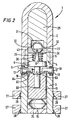
- the projectile (1) is substantially the same as the projectile of Figure 1.
- the projectile of Figure 2 differs from that of Figure 1 in the sense that the firing pin (7) includes two separate components.
- the conical tip portion (8), the stabilising disc (9) and the reduced diameter shaft portion (10) are formed as one component, and the base portion (11) is formed as a separate component.
- the base portion (11) is provided with a central blind bore (60) and an annular flange (61) at its outer radial periphery on its forward axial face (22).
- the reduced diameter shaft portion (10) is located in the blind bore (60) at its end furthest from the tip portion (8).
- the reduced diameter portion has an external diameter substantially the same as the internal diameter of the blind bore (60) and includes a shoulder (62) positioned part way along its length which is urged into engagement with a stepped annular recess (63) at the opening of the blind bore (61) by the compression spring (25).
- the safety pins (13) have a constant diameter shaft portion (18) which includes a slot (64).
- the slot (64) provides a detent which engages the annular flange (61) to prevent axial movement of the firing pin (7) in the direction of the initiator (23).
- slot (64) and annular flange (61) replace the reduced diameter portion (20) and outwardly splayed conical portion (21) of the safety pins (13) and the annular recess (12) of the projectile of Figure 1.
- the projectile of Figure 2 is fired in an identical manner to the projectile of Figure 1.
- On firing the acceleration force applied to the base portion (11) causes the base portion (11) to crush the frangible disc element (15). This allows the base portion (11) to move in the axial direction away from the initiator (23) relative to the shaft portion (10).
- the safety pins (13) become disengaged from the annular flange (61). Axial movement of the shaft portion (10) in the direction away from the initiator is prevented by engagement of the safety pins (13) with the disc portion (9).
- the initiator (23) is thereby held in its unarmed position by engagement of the tip portion (8) and the V-groove (41).
- the safety pins On exit from the barrel the safety pins eject radially outwards and the biassing force of the compression spring (25) urges the shaft portion (10) towards the base portion (11) in the axial direction away from the initiator (23). This causes the initiator (23) to be released from its unarmed position. The initiator (23) then rotates through 90 degrees to its armed position to arm the projectile.
- the projectile (1) is substantially the same as the projectile of Figure 1.
- the projectile of Figure 3 is different from that of Figure 1 in the sense that the safety pins (13) have a constant diameter shaft portion (42) which extends from the cap portion (17).
- the safety pins (13) are radially restrained in the throughbores (16) by the interfitting cartridge.
- the safety pins (13) can engage the forward facing axial side (22) of the of the base portion (11) to prevent axial movement of the firing pin (7) in the direction of the initiator (23), and can also engage the opposing axial side of the stabilising disc (9) to prevent axial movement of the firing pin (7) in the direction away from the initiator.
- the secondary mechanical releasable restraining means is provided by a plurality of circumferentially spaced radially movable elements (43).
- the elements (43) have a generally L-shaped cross-section and are interfitted in an annular groove (44) formed in a reduced diameter portion (45) of the firing pin (7) adjacent the base portion (11).
- the elements (43) are biased radially inwards into the annular groove (44) by spring biassing means (46) between the elements (43) and the casing (3).
- the elements (43) are accommodated in an annular recess (47) formed in the bore (6) at the end of the casing remote from the warhead (2).
- the annular recess (47) defines a stepped axial surface (49) in the bore (6).
- the radial dimension of the elements (43) is such that in the biased position shown the elements (43) extend radially outwards of the annular recess (44) and part way along the axial surface (48) into the annular recess (47). In this position the elements (43) define a radial gap (50) between the casing and their radially outer ends. Also in this position the elements (43) prevent axial movement of the firing pin (7) in the direction towards the initiator (23) by engagement with the stepped axial surface (49). The radial dimension of the gap (50) is marginally greater than that of the annular recess (45).
- the firing pin (7) is axially aligned in the bore (6) by location of its end furthest from the conical portion (8) in an aperture (51) provided in the end plate (24).
- the initiator (23) is non-movably retained in the explosive (29) by the annular plate (26).
- the projectile (1) On firing the projectile (1) leaves the cartridge (not shown) and travels along the smooth bore barrel. On exit from the barrel the restraint of the internal walls of the bore is removed and the safety pins (13) are immediately ejected. Movement of the firing pin (7) towards the initiator (23) is then prevented by engagement of the elements (43) and the axial surface (49) only. As the projectile exits from the barrel the fins (27) deploy and cause the projectile to rotate about its axis. At a predetermined point the rotation of the projectile generates sufficient centrifugal force on the elements (43) to force them radially outwards against the biassing force of the spring biassing means (46).
- FIG 4 shows a projectile (1) according to a first embodiment of the present invention.
- the projectile (1) of Figure 4 is formed in a similar way to the projectile arrangments of Figures 1 to 3 in that it has a hollow warhead (2) and a hollow casing (3).
- the warhead (2) and casing (3) are separately formed castings with interlocking means in the form of an externally threaded portion (70) on the warhead (2) and an internally threaded portion (71) on the casing (3).
- the projectile of Figure 4 is provided with a two piece firing pin (7).
- the firing pin (7) of the projectile of Figure 4 is similar to the firing pin (7) of the projectile of Figure 2 in the sense that the conical tip portion (8), the stabilising disc (9) and the shaft (10) are formed as one component, and the base portion (11) as a separate component.
- the shaft portion (10) is located in a central throughbore (72) in the base portion (11).
- the stabilising disc comprises a flat base (73) and a frusto conical side potion (74) which together provide a recess (75) on the initiator side of the stabilising disc.
- a cylindrical sleeve (76) is located in the bore (6) of the casing (3) adjacent the firing pin (7).
- An annular shoulder (77) is provided at the end of the sleeve (76) nearest the firing pin tip (8) to receive one end of a compression spring (25).
- the other end of the compression spring is located in the recess (75) to urge the flat base (73) of the stabilising disc into engagement with the base (11).
- the firing pin (7) is retained in the safety position shown by a primary mechanical releasable restraining means comprising at least one spring biased safety pin (78), and secondary releasable mechanical restraining means in the form of a frangible disc element (79).
- the safety release means additionally comprises a tertiary mechanical releasable restraining means in the form of at least one shear pin (80) disposed in a recess (83) in the base (11).
- the safety pin (78) is located in an inclined throughbore (81) in the side of the casing (3). At one end the safety pin (78) engages the frusto-conical side portion (74) of the stabilising disc (9).
- the safety pin (78) is spring loaded in a radially outwards direction by the compression spring (25) acting on the disc (9) and are restrained within its throughbore (81) by a fin (27) when in its folded-down condition as shown.
- the shear pin (80) is located in a throughbore (82) in the side of the casing (3) and extends within a recess (83) provided in the base (11).
- the shear pin (80) is provided with a reduced diameter frangible portion (84) which is positioned to correspond to the position between the recess (83) and the throughbore (82).
- the spring biased initiator (23) is located within the bore (6) of the casing.
- the initiator (23) is provided with a stepped outer surface (85) which is engaged by the tip of the conical portion (8) when the firing pin is in the safety position.
- the initiator (23) is spring loaded to its armed position which corresponds to the aperture (32) being aligned with the axis of the firing pin.
- the projectile of Figure 4 is fired in an identical manner to the projectiles of Figure 1 to 3.
- the acceleration force applied to the base portion (11) causes the base portion (11) to crush the frangible disc element (79) and the shear pin (80) to shear.
- This allows the base portion (11) to move in the axial direction away from the initiator (23) relative to the shaft portion (10).
- Axial movement of the shaft portion (10) in the direction away from the initiator is prevented by engagement of the safety pin (78) with the frusto-conical portion (74).
- the initiator (23) is thereby held in its unarmed position by engagement of the tip portion (8) with the stepped outer surface (85) when in the barrel of the smooth bore weapon.
- the fins (27) deploy and the safety pin (78) ejects radially outwards and the biassing force of the compression spring (25) urges the shaft portion (10) towards the base portion (11) in the axial direction away from the initiator (23). This causes the initiator (23) to be released from its unarmed position. The initiator (23) then rotates through approximately 30 degrees to its armed position to arm the projectile.
- Figure 4 has been described as comprising a single safety pin (78) and a single shear pin (80). In another embodiment these are supplemented by a second safety pin (78) and shear pin (80) positioned diametrically opposite each other respectively.
- the embodiment of the invention shown in Figure 4 provides a highly significant improvement in the safety of projectiles of this kind, based upon the important fact that, until the initiator (23) is permitted to move into its armed position, there is neither a direct line of impingement of the firing pin (7) into the initiator nor a direct line of communication between the initiator and the explosive (29). This is used to further advantage in the second and third embodiments of the invention illustrated in part in Figures 5(a), 5(b) and 6.
- the initiator (23) is contained within a cup-like construction (90), made of aluminium, and preferably surrounded with titanium foil (91), or otherwise coated with or bearing a layer of titanium, of thickness in the order of 0.001 inch.
- the warhead's explosive charge (29) is contained behind a shield (92) which adopts a top-hat like shape towards the initiator (23) with a thinned central portion (93).
- the cup-like structure (90, 91) is formed with a lid part (94), which faces towards the shield (92) so that, in general, when the projectile is safe, the lid part (94) lies in front of and parallel to the thinned portion (93) of the shield (92) when the initiator (23) is not in line with the main charge.
- Figure 5(b) is identical to Figure 5(a), except that it shows the armed condition, wherein the cup-like structure (90, 91) has been allowed to rotate so as to align the charge (23) with the thinned region (93) of the shield (92).
- the opened-out portions of the lid part (94) no longer overlie the thinned region (93) of the shield (92) and indeed assist in concentrating the initiator's charge into the main explosive charge (29) of the warhead; i.e. they provide a "fire channel” directing the initator's energy to the main charge.
- the principal difference from that of Figure 5 is that there is provided a shielding shutter (95) that is integral with, and thus rotates with, the initiator (23), thereby obviating the need for the lid part (94) to the cup-like structure (90, 91) which is otherwise as described in relation to Figure 5.
- the shutter (95) is shaped, dimensioned and crafted of suitable material to resist or at least lessen the impact on the main explosive charge (29) of an accidental discharge of the initiator charge. In this respect, it can be made relatively bulky since, of course, it is automatically moved out of the line of action between the initiator (23) and the main explosive charge (29) of the projectile when the initiator rotates to its armed position.
Landscapes
- Engineering & Computer Science (AREA)
- General Engineering & Computer Science (AREA)
- Portable Nailing Machines And Staplers (AREA)
- Aiming, Guidance, Guns With A Light Source, Armor, Camouflage, And Targets (AREA)
- Fuses (AREA)
- Toys (AREA)
- Chair Legs, Seat Parts, And Backrests (AREA)
- Ignition Installations For Internal Combustion Engines (AREA)
- Control Of Combustion (AREA)
- Feeding, Discharge, Calcimining, Fusing, And Gas-Generation Devices (AREA)
Claims (13)
- Projectile (1) pour une arme légère, le projectile comprenant :dans lequel l'étui (3) contient également un moyen de libération de sécurité pour restreindre de façon libérable le percuteur (7), à l'encontre de ladite force élastique qui tend à éloigner le percuteur (7) de l'amorceur (23), dans une position de sécurité, ce par quoi ledit amorceur (23) est maintenu, par engagement avec le percuteur (7), dans son état de sécurité, à l'encontre d'une force d'armement tendant à solliciter l'amorceur (23) vers l'état armé ;un étui (3) généralement tubulaire, ayant un percuteur (7) déplaçable axialement ;un ressort de compression (25) fournissant une force élastique ;un cône de charge (2) ayant une charge explosive ; etun amorceur (23) ayant des états de sécurité et armé et capable, lorsqu'il est dans son état armé et lorsqu'il est heurté par une force suffisante par ledit percuteur (7), de faire détoner la charge explosive dudit cône de charge (2) ;
dans lequel le moyen de libération de sécurité comprend un premier (11, 79, 80) et un second (27, 78) moyen mécanique ;
dans lequel ledit premier moyen mécanique comprend au moins un composant (79, 80) construit pour être cassant en réponse aux forces éprouvées lors de la mise à feu du projectile, la résistance de l'élément cassant étant suffisante pour résister aux forces d'accélération jusqu'à 500 g ; et
dans lequel ledit second moyen mécanique comprend au moins un composant (78) disposé et configuré de façon à être éjecté de l'étui (3) sous l'influence de ladite force élastique lorsque le projectile quitte l'arme, permettant à ladite force élastique d'éloigner ledit percuteur (7) dudit amorceur (23) dans une mesure permettant audit amorceur d'être sollicité dans son état armé. - Projectile pour une arme légère selon la revendication 1, caractérisé par le fait que ledit percuteur comprend une partie de base (11) déplaçable axialement, séparée.
- Projectile pour une arme légère selon la revendication 2, caractérisé par le fait que ledit composant cassant comprend une broche de cisaillement (80) positionnée pour supporter ladite partie de base (11) avant la mise à feu du projectile (1).
- Projectile pour une arme légère selon l'une des revendications 2 ou 3, caractérisé par le fait que ledit composant cassant comprend un élément de disque (79) disposé entre ladite partie de base (11) et l'étui (3) pour supporter ladite partie de base (11) avant la mise à feu du projectile (1).
- Projectile pour une arme légère selon l'une quelconque des revendications précédentes, caractérisé par le fait que l'amorceur (23) est sollicité pour se déplacer de son état de sécurité à son état armé par rotation autour d'un axe perpendiculaire à l'axe dudit étui.
- Projectile pour une arme légère selon l'une quelconque des revendications précédentes, caractérisé par le fait que la force élastique appliquée au percuteur (7) est fournie par ledit ressort de compression (25) qui a une raideur suffisante pour empêcher le percuteur de se déplacer dans l'amorceur (23) en raison de la décélération éprouvée par le projectile (1) alors qu'il quitte la bouche d'une arme légère.
- Projectile pour une arme légère selon l'une quelconque des revendications précédentes, caractérisé par le fait que le composant éjectable dudit second moyen mécanique comprend au moins une broche de sécurité (78) sollicitée par ladite force élastique dudit ressort de compression (25).
- Projectile pour une arme légère selon la revendication 7, caractérisé par le fait que deux broches de sécurité sollicitées par ressort sont prévues en vue d'une libération dans des directions radiales opposées.
- Projectile pour une arme légère selon l'une quelconque des revendications précédentes, caractérisé par le fait que ledit étui (3) supporte plusieurs ailettes de stabilisation (27) contraintes de s'étendre contre l'étui avant la mise à feu du projectile, mais capables de se déployer lorsque le projectile quitte l'arme ; et dans lequel au moins l'une desdites ailettes empêche l'éjection du composant éjectable (78) dudit second moyen mécanique jusqu'à ce que ledit déploiement ait lieu, le déploiement étant assisté par le mouvement dudit percuteur (7) sous ladite force élastique.
- Projectile pour une arme légère selon la revendication 9, caractérisé par le fait que ledit percuteur (7) est muni d'un disque de stabilisation (9) ayant une partie latérale tronconique (74) disposée en contact avec le composant éjectable (78) dudit second moyen mécanique.
- Projectile pour une arme légère selon l'une quelconque des revendications précédentes, caractérisé par le fait que ledit amorceur (23) est réalisé pour générer, lorsqu'il est dans son état armé, une charge explosive d'amorçage en réponse à un impact sur celui-ci dudit percuteur (7) et comprend un moyen pour amener ladite charge explosive d'amorçage à se conformer à une forme prédéterminée autour d'un axe d'amorceur et dans lequel ledit axe d'amorceur est hors d'alignement avec l'axe de mouvement dudit percuteur (7) lorsqu'il est maintenu dans son état de sécurité.
- Projectile pour une arme légère selon la revendication 11, caractérisé par le fait que, lorsque l'axe dudit amorceur (23) est hors d'alignement avec l'axe de mouvement dudit percuteur (7), un moyen d'écran de protection (95) est interposé entre la charge d'amorçage et celle dudit cône de charge.
- Projectile pour une arme légère selon la revendication 12, caractérisé par le fait que ladite charge explosive d'amorçage est contenue dans une structure (90) de type coupe et ledit écran de protection comprend une partie (94a) de ladite structure.
Applications Claiming Priority (5)
| Application Number | Priority Date | Filing Date | Title |
|---|---|---|---|
| GB9807290 | 1998-04-03 | ||
| GBGB9807290.3A GB9807290D0 (en) | 1998-04-03 | 1998-04-03 | Safety system |
| GB9817471 | 1998-08-11 | ||
| GBGB9817471.7A GB9817471D0 (en) | 1998-08-11 | 1998-08-11 | Safety system |
| PCT/GB1999/001042 WO1999051934A1 (fr) | 1998-04-03 | 1999-04-06 | Systeme de securite pour amorce de projectile |
Publications (2)
| Publication Number | Publication Date |
|---|---|
| EP1068484A1 EP1068484A1 (fr) | 2001-01-17 |
| EP1068484B1 true EP1068484B1 (fr) | 2004-05-26 |
Family
ID=26313433
Family Applications (1)
| Application Number | Title | Priority Date | Filing Date |
|---|---|---|---|
| EP99914666A Expired - Lifetime EP1068484B1 (fr) | 1998-04-03 | 1999-04-06 | Systeme de securite pour amorce de projectile |
Country Status (11)
| Country | Link |
|---|---|
| EP (1) | EP1068484B1 (fr) |
| KR (1) | KR100590279B1 (fr) |
| AT (1) | ATE268000T1 (fr) |
| AU (1) | AU3339599A (fr) |
| BR (1) | BR9909431A (fr) |
| CA (1) | CA2326432C (fr) |
| DE (1) | DE69917621D1 (fr) |
| ES (1) | ES2222698T3 (fr) |
| IL (2) | IL138823A0 (fr) |
| MX (1) | MXPA00009711A (fr) |
| WO (1) | WO1999051934A1 (fr) |
Cited By (1)
| Publication number | Priority date | Publication date | Assignee | Title |
|---|---|---|---|---|
| US7316122B1 (en) | 2004-01-06 | 2008-01-08 | Dippin' Dots, Inc. | Tray for producing particulate food products |
Families Citing this family (6)
| Publication number | Priority date | Publication date | Assignee | Title |
|---|---|---|---|---|
| GB0109277D0 (en) | 2001-04-12 | 2001-05-30 | Olympic Technologies Ltd | Small arms projectile |
| GB0111171D0 (en) * | 2001-05-08 | 2001-06-27 | Special Cartridge Company Ltd | Projictile |
| GB0301690D0 (en) | 2003-01-24 | 2003-02-26 | Olympic Technologies Ltd | Safety system |
| KR100616470B1 (ko) * | 2004-12-29 | 2006-08-29 | 국방과학연구소 | 슬라이더 차단식 소형 안전장전장치 |
| EP1902938B1 (fr) * | 2006-09-01 | 2015-08-05 | Whitehead Sistemi Subacquei S.p.A. | Flotteur pour dispositif lancé par avion dans la mer, en particulier pour contre-mesure |
| GB2466257B (en) * | 2008-12-17 | 2013-08-21 | Olympic Technologies Ltd | Safety system |
Citations (1)
| Publication number | Priority date | Publication date | Assignee | Title |
|---|---|---|---|---|
| GB606087A (en) * | 1942-09-07 | 1948-08-05 | C V Chemische Fabriek Rids | Improvements relating to insect-repellents or insecticides |
Family Cites Families (12)
| Publication number | Priority date | Publication date | Assignee | Title |
|---|---|---|---|---|
| DE308558C (fr) * | ||||
| FR424890A (fr) * | 1911-01-14 | 1911-05-26 | Louis Dervaux | Fusée percutante |
| CH79515A (de) * | 1917-07-06 | 1918-12-02 | Ehrhardt & Sehmer Aktiengesell | Geschoßzünder |
| FR627004A (fr) * | 1926-01-02 | 1927-09-24 | Dispositif de sûreté pour fusées ou amorces d'armes à feu | |
| CH207871A (de) * | 1939-02-11 | 1939-12-15 | Gazda Antoine | Aufschlagzünder. |
| US2458405A (en) * | 1943-04-14 | 1949-01-04 | Harry J Nichols | Fuse |
| US2554586A (en) * | 1943-09-11 | 1951-05-29 | Robert D Miller | Detent |
| US2537855A (en) * | 1944-06-09 | 1951-01-09 | Henry H Porter | Point contact fuse |
| US2564797A (en) * | 1945-05-05 | 1951-08-21 | Marion L J Lambert | Fuse |
| BE540826A (fr) * | 1949-12-23 | |||
| NL239855A (fr) * | 1953-12-24 | Brandt Soc Nouv Ets | ||
| GB8823264D0 (en) | 1988-10-05 | 1989-03-30 | Shaphyr Shalom | Projectile |
-
1999
- 1999-04-06 EP EP99914666A patent/EP1068484B1/fr not_active Expired - Lifetime
- 1999-04-06 ES ES99914666T patent/ES2222698T3/es not_active Expired - Lifetime
- 1999-04-06 BR BR9909431-2A patent/BR9909431A/pt not_active IP Right Cessation
- 1999-04-06 AU AU33395/99A patent/AU3339599A/en not_active Abandoned
- 1999-04-06 IL IL13882399A patent/IL138823A0/xx active IP Right Grant
- 1999-04-06 WO PCT/GB1999/001042 patent/WO1999051934A1/fr not_active Ceased
- 1999-04-06 DE DE69917621T patent/DE69917621D1/de not_active Expired - Lifetime
- 1999-04-06 AT AT99914666T patent/ATE268000T1/de not_active IP Right Cessation
- 1999-04-06 KR KR1020007011015A patent/KR100590279B1/ko not_active Expired - Fee Related
- 1999-04-06 MX MXPA00009711A patent/MXPA00009711A/es active IP Right Grant
- 1999-04-06 CA CA002326432A patent/CA2326432C/fr not_active Expired - Fee Related
-
2000
- 2000-10-03 IL IL138823A patent/IL138823A/en not_active IP Right Cessation
Patent Citations (1)
| Publication number | Priority date | Publication date | Assignee | Title |
|---|---|---|---|---|
| GB606087A (en) * | 1942-09-07 | 1948-08-05 | C V Chemische Fabriek Rids | Improvements relating to insect-repellents or insecticides |
Cited By (1)
| Publication number | Priority date | Publication date | Assignee | Title |
|---|---|---|---|---|
| US7316122B1 (en) | 2004-01-06 | 2008-01-08 | Dippin' Dots, Inc. | Tray for producing particulate food products |
Also Published As
| Publication number | Publication date |
|---|---|
| AU3339599A (en) | 1999-10-25 |
| BR9909431A (pt) | 2001-09-11 |
| KR100590279B1 (ko) | 2006-06-15 |
| EP1068484A1 (fr) | 2001-01-17 |
| ATE268000T1 (de) | 2004-06-15 |
| IL138823A0 (en) | 2001-11-25 |
| KR20010034736A (ko) | 2001-04-25 |
| MXPA00009711A (es) | 2002-04-24 |
| WO1999051934A1 (fr) | 1999-10-14 |
| IL138823A (en) | 2007-06-17 |
| ES2222698T3 (es) | 2005-02-01 |
| CA2326432C (fr) | 2007-12-11 |
| HK1030257A1 (en) | 2001-04-27 |
| DE69917621D1 (de) | 2004-07-01 |
| CA2326432A1 (fr) | 1999-10-14 |
Similar Documents
| Publication | Publication Date | Title |
|---|---|---|
| EP0284923B1 (fr) | Fusée pour une sous-munition | |
| US6604467B2 (en) | Safety system for a projectile fuse | |
| US9562755B2 (en) | Safe and arm mechanisms and methods for explosive devices | |
| CN113865449A (zh) | 线膛火炮榴弹弹底机械触发引信 | |
| EP1155279B1 (fr) | Fusee percutante a destruction automatique | |
| US5189250A (en) | Projectile for smooth bore weapon | |
| EP2102581B1 (fr) | Fusée percutante fonctionnant par autodestruction | |
| CA2326432C (fr) | Systeme de securite pour amorce de projectile | |
| KR20110018280A (ko) | 기계적 커맨드 투 아암 신관 | |
| US2692557A (en) | Fuse | |
| EP0363079B1 (fr) | Projectile pour arme à canon lisse | |
| US3961578A (en) | Point-detonating projectile fuze | |
| US4457232A (en) | Artillery fuze for practice and tactical munitions | |
| US2541603A (en) | Fuse | |
| HK1030257B (en) | Safety system for a projectile fuse | |
| KR101879944B1 (ko) | 지연장전부와 격침부 사이의 기폭정렬이 보장되는 충격신관 | |
| ZA200506220B (en) | Safety system for the ignition chain of a projectile fuze | |
| US6318269B1 (en) | Air current operated projectile fuze | |
| KR20180037341A (ko) | 격침의 오발을 방지하는 지연장전부를 구비한 충격신관 | |
| EP0102633A1 (fr) | Fusée pour projectiles giratoires |
Legal Events
| Date | Code | Title | Description |
|---|---|---|---|
| PUAI | Public reference made under article 153(3) epc to a published international application that has entered the european phase |
Free format text: ORIGINAL CODE: 0009012 |
|
| 17P | Request for examination filed |
Effective date: 20001102 |
|
| AK | Designated contracting states |
Kind code of ref document: A1 Designated state(s): AT BE CH CY DE DK ES FI FR GB GR IE IT LI LU MC NL PT SE |
|
| 17Q | First examination report despatched |
Effective date: 20010219 |
|
| GRAH | Despatch of communication of intention to grant a patent |
Free format text: ORIGINAL CODE: EPIDOS IGRA |
|
| GRAS | Grant fee paid |
Free format text: ORIGINAL CODE: EPIDOSNIGR3 |
|
| GRAS | Grant fee paid |
Free format text: ORIGINAL CODE: EPIDOSNIGR3 |
|
| GRAA | (expected) grant |
Free format text: ORIGINAL CODE: 0009210 |
|
| AK | Designated contracting states |
Kind code of ref document: B1 Designated state(s): AT BE CH CY DE DK ES FI FR GB GR IE IT LI LU MC NL PT SE |
|
| PG25 | Lapsed in a contracting state [announced via postgrant information from national office to epo] |
Ref country code: NL Free format text: LAPSE BECAUSE OF FAILURE TO SUBMIT A TRANSLATION OF THE DESCRIPTION OR TO PAY THE FEE WITHIN THE PRESCRIBED TIME-LIMIT Effective date: 20040526 Ref country code: FI Free format text: LAPSE BECAUSE OF FAILURE TO SUBMIT A TRANSLATION OF THE DESCRIPTION OR TO PAY THE FEE WITHIN THE PRESCRIBED TIME-LIMIT Effective date: 20040526 Ref country code: AT Free format text: LAPSE BECAUSE OF FAILURE TO SUBMIT A TRANSLATION OF THE DESCRIPTION OR TO PAY THE FEE WITHIN THE PRESCRIBED TIME-LIMIT Effective date: 20040526 |
|
| REG | Reference to a national code |
Ref country code: GB Ref legal event code: FG4D |
|
| REG | Reference to a national code |
Ref country code: CH Ref legal event code: EP |
|
| REG | Reference to a national code |
Ref country code: IE Ref legal event code: FG4D |
|
| REF | Corresponds to: |
Ref document number: 69917621 Country of ref document: DE Date of ref document: 20040701 Kind code of ref document: P |
|
| PG25 | Lapsed in a contracting state [announced via postgrant information from national office to epo] |
Ref country code: SE Free format text: LAPSE BECAUSE OF FAILURE TO SUBMIT A TRANSLATION OF THE DESCRIPTION OR TO PAY THE FEE WITHIN THE PRESCRIBED TIME-LIMIT Effective date: 20040826 Ref country code: GR Free format text: LAPSE BECAUSE OF FAILURE TO SUBMIT A TRANSLATION OF THE DESCRIPTION OR TO PAY THE FEE WITHIN THE PRESCRIBED TIME-LIMIT Effective date: 20040826 Ref country code: DK Free format text: LAPSE BECAUSE OF FAILURE TO SUBMIT A TRANSLATION OF THE DESCRIPTION OR TO PAY THE FEE WITHIN THE PRESCRIBED TIME-LIMIT Effective date: 20040826 |
|
| PG25 | Lapsed in a contracting state [announced via postgrant information from national office to epo] |
Ref country code: DE Free format text: LAPSE BECAUSE OF FAILURE TO SUBMIT A TRANSLATION OF THE DESCRIPTION OR TO PAY THE FEE WITHIN THE PRESCRIBED TIME-LIMIT Effective date: 20040827 |
|
| REG | Reference to a national code |
Ref country code: CH Ref legal event code: NV Representative=s name: R. A. EGLI & CO. PATENTANWAELTE |
|
| NLV1 | Nl: lapsed or annulled due to failure to fulfill the requirements of art. 29p and 29m of the patents act | ||
| REG | Reference to a national code |
Ref country code: ES Ref legal event code: FG2A Ref document number: 2222698 Country of ref document: ES Kind code of ref document: T3 |
|
| ET | Fr: translation filed | ||
| REG | Reference to a national code |
Ref country code: HK Ref legal event code: GR Ref document number: 1030257 Country of ref document: HK |
|
| PLBE | No opposition filed within time limit |
Free format text: ORIGINAL CODE: 0009261 |
|
| STAA | Information on the status of an ep patent application or granted ep patent |
Free format text: STATUS: NO OPPOSITION FILED WITHIN TIME LIMIT |
|
| PG25 | Lapsed in a contracting state [announced via postgrant information from national office to epo] |
Ref country code: LU Free format text: LAPSE BECAUSE OF NON-PAYMENT OF DUE FEES Effective date: 20050406 Ref country code: IE Free format text: LAPSE BECAUSE OF NON-PAYMENT OF DUE FEES Effective date: 20050406 Ref country code: CY Free format text: LAPSE BECAUSE OF FAILURE TO SUBMIT A TRANSLATION OF THE DESCRIPTION OR TO PAY THE FEE WITHIN THE PRESCRIBED TIME-LIMIT Effective date: 20050406 |
|
| PG25 | Lapsed in a contracting state [announced via postgrant information from national office to epo] |
Ref country code: MC Free format text: LAPSE BECAUSE OF NON-PAYMENT OF DUE FEES Effective date: 20050430 |
|
| 26N | No opposition filed |
Effective date: 20050301 |
|
| PG25 | Lapsed in a contracting state [announced via postgrant information from national office to epo] |
Ref country code: PT Free format text: LAPSE BECAUSE OF NON-PAYMENT OF DUE FEES Effective date: 20041026 |
|
| PGFP | Annual fee paid to national office [announced via postgrant information from national office to epo] |
Ref country code: CH Payment date: 20080725 Year of fee payment: 10 |
|
| REG | Reference to a national code |
Ref country code: CH Ref legal event code: PL |
|
| PG25 | Lapsed in a contracting state [announced via postgrant information from national office to epo] |
Ref country code: LI Free format text: LAPSE BECAUSE OF NON-PAYMENT OF DUE FEES Effective date: 20090430 Ref country code: CH Free format text: LAPSE BECAUSE OF NON-PAYMENT OF DUE FEES Effective date: 20090430 |
|
| PGFP | Annual fee paid to national office [announced via postgrant information from national office to epo] |
Ref country code: FR Payment date: 20120608 Year of fee payment: 14 Ref country code: BE Payment date: 20120531 Year of fee payment: 14 Ref country code: GB Payment date: 20120430 Year of fee payment: 14 |
|
| PGFP | Annual fee paid to national office [announced via postgrant information from national office to epo] |
Ref country code: IT Payment date: 20120420 Year of fee payment: 14 |
|
| PGFP | Annual fee paid to national office [announced via postgrant information from national office to epo] |
Ref country code: ES Payment date: 20120530 Year of fee payment: 14 |
|
| BERE | Be: lapsed |
Owner name: *SPECIAL CARTRIDGE CY LTD Effective date: 20130430 |
|
| GBPC | Gb: european patent ceased through non-payment of renewal fee |
Effective date: 20130406 |
|
| PG25 | Lapsed in a contracting state [announced via postgrant information from national office to epo] |
Ref country code: BE Free format text: LAPSE BECAUSE OF NON-PAYMENT OF DUE FEES Effective date: 20130430 Ref country code: GB Free format text: LAPSE BECAUSE OF NON-PAYMENT OF DUE FEES Effective date: 20130406 |
|
| REG | Reference to a national code |
Ref country code: FR Ref legal event code: ST Effective date: 20131231 |
|
| PG25 | Lapsed in a contracting state [announced via postgrant information from national office to epo] |
Ref country code: FR Free format text: LAPSE BECAUSE OF NON-PAYMENT OF DUE FEES Effective date: 20130430 Ref country code: IT Free format text: LAPSE BECAUSE OF NON-PAYMENT OF DUE FEES Effective date: 20130406 |
|
| REG | Reference to a national code |
Ref country code: ES Ref legal event code: FD2A Effective date: 20150710 |
|
| PG25 | Lapsed in a contracting state [announced via postgrant information from national office to epo] |
Ref country code: ES Free format text: LAPSE BECAUSE OF NON-PAYMENT OF DUE FEES Effective date: 20130407 |