EP1068797A2 - Dispositif de mélange et de distribution d'alimentation - Google Patents
Dispositif de mélange et de distribution d'alimentation Download PDFInfo
- Publication number
- EP1068797A2 EP1068797A2 EP00109724A EP00109724A EP1068797A2 EP 1068797 A2 EP1068797 A2 EP 1068797A2 EP 00109724 A EP00109724 A EP 00109724A EP 00109724 A EP00109724 A EP 00109724A EP 1068797 A2 EP1068797 A2 EP 1068797A2
- Authority
- EP
- European Patent Office
- Prior art keywords
- flap
- closure flap
- opening
- metering slide
- lever
- Prior art date
- Legal status (The legal status is an assumption and is not a legal conclusion. Google has not performed a legal analysis and makes no representation as to the accuracy of the status listed.)
- Granted
Links
Images

Classifications
-
- A—HUMAN NECESSITIES
- A01—AGRICULTURE; FORESTRY; ANIMAL HUSBANDRY; HUNTING; TRAPPING; FISHING
- A01D—HARVESTING; MOWING
- A01D90/00—Vehicles for carrying harvested crops with means for selfloading or unloading
- A01D90/10—Unloading means
- A01D90/105—Automatic side-emptying forage wagons
-
- A—HUMAN NECESSITIES
- A01—AGRICULTURE; FORESTRY; ANIMAL HUSBANDRY; HUNTING; TRAPPING; FISHING
- A01K—ANIMAL HUSBANDRY; AVICULTURE; APICULTURE; PISCICULTURE; FISHING; REARING OR BREEDING ANIMALS, NOT OTHERWISE PROVIDED FOR; NEW BREEDS OF ANIMALS
- A01K5/00—Feeding devices for stock or game ; Feeding wagons; Feeding stacks
- A01K5/001—Fodder distributors with mixer or shredder
-
- A—HUMAN NECESSITIES
- A01—AGRICULTURE; FORESTRY; ANIMAL HUSBANDRY; HUNTING; TRAPPING; FISHING
- A01K—ANIMAL HUSBANDRY; AVICULTURE; APICULTURE; PISCICULTURE; FISHING; REARING OR BREEDING ANIMALS, NOT OTHERWISE PROVIDED FOR; NEW BREEDS OF ANIMALS
- A01K5/00—Feeding devices for stock or game ; Feeding wagons; Feeding stacks
- A01K5/001—Fodder distributors with mixer or shredder
- A01K5/004—Fodder distributors with mixer or shredder with mixing or shredding element rotating on vertical axis
-
- B—PERFORMING OPERATIONS; TRANSPORTING
- B01—PHYSICAL OR CHEMICAL PROCESSES OR APPARATUS IN GENERAL
- B01F—MIXING, e.g. DISSOLVING, EMULSIFYING OR DISPERSING
- B01F35/00—Accessories for mixers; Auxiliary operations or auxiliary devices; Parts or details of general application
- B01F35/75—Discharge mechanisms
- B01F35/751—Discharging by opening a gate, e.g. using discharge paddles
Definitions
- the invention relates to a device known in the preamble of claim 1 Art.
- each is used as a protective element serving shutter operated by a hydraulic or pneumatic cylinder.
- the top flap is hinged on both sides with bellows connected to the container side walls. Because the flap is in a continuous Movement is opened, possibly in synchronism with the opening movement the metering slide, the metering slide is almost in its full open position, when the flap reaches its full swing position. If the metering slide makes its initial opening stroke, the lower edge of the Closure flap still relatively close to the receptacle, so that then through the Opening below the metering slide by hand into the working area of the mixing and Conveyor element can be gripped. This means significant and not operating risk corresponding to the regulations. Furthermore, the rising slowly Closing flap hinder the discharge of the bulk material.
- the invention has for its object a device of the aforementioned To create a way that reduces the operational risk when the protective element is issued and a hindrance to the bulk material discharge by the protective element is avoided becomes.
- the positive actuation mechanism actuates the
- a protective element designed as a closure flap is active so that the Locking flap in a largely independent of the movement of the metering slide rapid and rapid movement immediately brought into the full open position and is held in it.
- the flap is already in its full Open position in which e.g. their lower margin such a large safety distance to the conveying and mixing element that that of the rotating mixing and conveying element outgoing operational risk is significantly reduced.
- the rapid forced movement of the closure flap to its full open position avoided that it disrupts bulk material discharge, so that no blockages occur.
- the closure flap leading to and faster than the opening movement of the metering slide forcibly fully open and lagging to and therefore faster than the metering slide closed.
- the protective element can be a closure flap that can be swung out at the bottom, or a plate or grid that can be pushed off parallel to itself, etc.
- the bottom edge of the flap is particularly useful in the full Opening position of the closure flap in at least one in accordance with the regulations Safety distance from the conveying and positioned behind the discharge opening Mixing element as soon as and as long as the metering slide opens an opening through which could be gripped by hand inside the receptacle. This distance should currently be at least 550 mm due to official regulations.
- the forced actuation mechanism could be initiated by initiating the Adjustment of the metering slide can be triggered.
- Forced operation mechanism through the adjustment device or the metering slide to operate to ensure the desired safety function.
- a structurally simple and reliable positive actuation mechanism works with an opening spring and an opening lever as well as a driver coupling, which transmits the opening or closing movement of the metering slide.
- the closure flap is actively opened by the opening spring, whereby the initial small opening stroke of the metering slide acts as a trigger.
- the opening spring then holds the flap in the full swing open position.
- the opening lever is approximately parallel with its inner end is guided to the container wall, and extends up to the closure flap, then not only the initial opening stroke of the metering slide but also the Opening movement of the opening spring translated into large, so that the closure flap goes to the full open position in a rapid stroke, even if the Metering slide moves slowly.
- closure flap Since the inner end of the opening lever is also in the full swing open position the closure flap is located near the lower edge of the discharge opening only one important for the safety function for the movements of the closure flap very small, permitted stroke of the metering slide, e.g. just a few centimeters.
- the opening lever consists of two bends interconnected, on the closure flap and on the receptacle each pivotally mounted lever parts, in the buckling area of the opening spring attacks.
- the lever parts are expediently approximately in the stretched relative position, corresponding to the full pivoting position supported with a slight kink to the direction of collapse so that it itself when the closing flap is swiveled over the pulling element is caused to fold into the correct starting position.
- the tension element should be relatively close engage on the swivel axis of the flap to get it in relatively late pull the swivel position.
- This deflection flap should be inside when the flap is closed Position and only when the flap is fully open protrude outward beyond the outer contour to the driving width in the device not increase inappropriately. Is the deflection valve effective with the Closure flap or its positive actuation mechanism connected, then it takes the automatically when or after opening the flap outer position. However, it is also possible to separate the deflector and only can be adjusted to the outside if necessary.
- An inclined or convexly curved deflection surface on the deflection flap guides this Bulk goods with no significant discharge resistance evenly and distributing outside below.
- the lever can be in an elongated hole in the bottom of the container be led and then takes over the leadership of the lower end of the Opening lever.
- the lower edge of the flap is also lower than the inner one in the full swing-open position Bottom of the receptacle.
- Forced operation mechanisms are expedient on both sides of the discharge opening provided for the flap.
- the width of the closure flap is chosen so large that there is a safety distance on both sides of the discharge opening defines how it complies with official regulations, e.g. at least 230 mm up to the dangerous extreme circumference of the conveying mixing element.
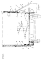
- Fig. 1 is on a chassis provided with a so-called feed mixing wagon a device V for mixing and discharging bulk material, in particular short- and long-fiber silage, shown that a receptacle 1 and in the embodiment shown in the receptacle 1 one by one vertical axis rotatable screw with a frustoconical surface as Mixing and conveying element 2 on the container bottom 15,
- opposite Container walls 3 are shaped through window-like discharge openings 4 which can either be discharged to one or the other side of bulk goods.
- Each discharge opening 4 is a metering slide D and in this case a closure flap K assigned protective element T assigned.
- the metering slide will by means of an adjusting device 6 between the open position shown on the right in FIG.
- the closure flap K for example, on an outside above the discharge opening 4 Pivot axis 13 is pivotally held by means of a positive actuation mechanism Z between the full protective or pivoted position shown on the right in FIG. 1 A and the full swivel position B shown in Fig. 1 on the left and back moved (e.g. swiveled).
- the adjustment device 6 engages with a console 7 on the metering slide, which also projects into the discharge opening 4 Has stop 8 near its lower edge.
- the bottom edge of the flap K is denoted by 5. It lies in the full pivoted-up position shown on the right in FIG. 1 deeper than the inner bottom 15 of the receptacle 1 (Fig. 2, reference numerals S).
- An opening spring F is provided in the positive actuation mechanism Z, which actuates an opening lever H of the closure flap K.
- the closure flap K from the full swivel position B is set to the full swing-open position A as soon as the metering slide an initial, small opening stroke x (just a few centimeters) from his Has executed the closed position.
- the lower edge 5 of the closure flap K is located then at a safety distance Y equal to or greater than 550 mm from the Discharge opening 4 or the outermost part of the mixing or conveying element 2 in the receptacle 1.
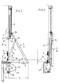
- Fig. 2 is an option arranged below the discharge opening 4 adjustable Deflection flap K1 is provided which moves back and forth between the positions of FIGS. 2 and 3 can be manufactured, and serves to emerge from the discharge opening 4 Guide the bulk material downwards to the outside.
- the deflector flap K1 is not absolutely necessary, If present, for example, it can be heavily soiled prevent the wheels.
- the positive actuation mechanism Z in Fig. 2 has a one-piece as the opening lever A. long lever 12, with its lower inner end in a guide 9 can be guided approximately vertically. In the embodiment shown, a takes over with the lever 12 coupled lever 20 this guide. To do this, enforces Lever 20 an elongated hole 9 in the container bottom 15.
- the opening spring F is at 10 am Receiving container 1 or the guide 9 anchored and extends to the lower End of the lever 12 or to a cam 11 arranged there.
- the cam 11 is aligned with the path of movement of the stop 8 on the metering slide D and lies in the fully swiveled-up position of the closure flap K with the distance x above the level of the inner bottom 15 of the receptacle.
- the distance x is only a few centimeters and corresponds to the initial opening stroke of the metering slide from his shooting position, e.g. approx. 50 mm.
- the lever 12 is with its upper one End connected in a pivot bearing 14 to the closure flap K, whereby the pivot bearing 14 is relatively close to the upper pivot axis 13, i.e. in about the first quarter of the length of the flap K, starting from the Swivel axis 13.
- a bar 16 be provided, optionally with the metering slide D for cutting off a Bulk goods strand works together, for which the metering slide D on his lower edge 23 is formed with a cutting-like or bevelled punched edge 24 is.
- the deflector flap K1 is in a box-like base 17 on a deep one Pivot 18 is pivotally mounted and has an oblique or convexly curved Deflection surface 19, which is in the pivoted-out position of the deflection flap K1 (FIG. 2) approximately continues the bar 16, in the pivoted-in position according to FIG. 3 however, has withdrawn behind the contour of the adjusting device 6.
- the deflection flap K1 is coupled to the cam 11 via the actuating lever 20.
- the deflection flap K1 could alternatively have its own adjustment mechanism.
- the relative positions of the stop 8 and the cam 11 in the vertical direction are so selected that the closure flap K in the closed position of the metering slide D in the full swivel position B of Fig. 3 is pulled.
- the opening spring F pulls the cam 11 and thus the opening lever H upwards, this movement being caused by the articulation of the lever 12 translated relatively high up on the closure flap K.
- the opening spring F has the closing flap via the opening lever H. K already brought into the full pivot position A of FIG. 2.
- the full swivel position can be defined by limit stops, not shown his. The further opening movement of the metering slide D no longer has any influence on the closure flap K.
- the deflection flap K1 If the deflection flap K1 is provided, it will be within the initial opening stroke x of the metering slide K, also via the opening spring F, into the swung out Position brought the Fig. 2.
- the positive actuation mechanism Z has one of the parts 12a and 12b existing opening lever H.
- the lever parts 12a, 12b are with their one Ends at 11 'and 14' on the receptacle and on the closure flap K pivoted and connected to each other at 21 bendable.
- the snap connection 21 is advantageously provided a kink restriction, so that the lever parts 12a, 12b can only be brought into the weak kink position shown in FIG. 4.
- the opening spring F which is arranged higher than in Fig. 2, is at 10 ' Receptacle anchored and engages in the area of the kink connection 21 Opening lever H on.
- the opening spring F has the task of closing the flap K in to bring the full pivoting position A shown in Fig.
- a tension member 22 is provided which is flexible but essentially inextensible should be (cable, cable, chain or generally anchored to the metering slide D and with the other end on the closure flap K, and expediently there close to the pivot axis 13.
- At least one closing damper P is effective, e.g. designed as a buffer, spring or rubber damper and on the flap K or can be attached to the receptacle 1. If applicable, are on the closure flap K is provided with two dampers P.
- the elongated length of the tension element 22 (FIG. 5) is dimensioned such that the closure flap K first towards the end of the closing movement of the metering slide D in 5 is pulled, however, as in FIG. 2 already is adjusted to its full swiveling position as soon as the metering slide is in its position initial small opening stroke x executes.
- the opening spring F pulls the lever parts 12a, 12b from the one in FIG. 5 shown folded position in the position shown in Fig. 4.
- FIGS. 4, 5 there is no deflection flap K1 as in FIGS. 2 and 3 intended.
- a deflection flap in this embodiment to provide.
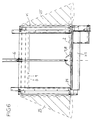
- the closure flap K is over on both long sides Bellows 25 or metal plates or the like. Connected to the receptacle 1 is, the metal plates collapsible through joints or rubber parts or can be pushed into one another. This is to prevent bulk goods from being uncontrolled from the side falls out and that from the outside around the closure flap K in the Interior of the mixing and conveying element 2 can be accessed.
- closure flap K is considerably wider than the discharge opening 4, so that a required safety distance to the dangerous side Mixing and conveying element 2 is observed, e.g. at least 230 mm.
- the Bellows 25 cover on the long sides of the closure flap K.
- the metering slide D for example the shape of a rectangular or square plate is smaller than the closure flap K.
- the lower edge 23 of the metering slide D is as a knife-like or bevelled punched edge 24 is formed, which cooperate with the bar 16 can.
- the punched edge 24 is expediently from the outside downward beveled inside.
- the metering slide at least the Force actuation mechanism for the closure flap K triggers or even actuates.
- the forced actuation mechanism Z through the Actuating device 6 to actuate or trigger. That is, the closure flap K could already be adjusted to its full swivel position A when the Metering slide only a few millimeters from its fully closed position towards Open position is moved. It would also be possible to make the closure flap trapezoidal form, the lower edge 5 of the flap the longer trapezoidal base represents. The lower edge 5 of the closure flap K could also be roof-shaped or run rounded so that the outer corners are as deep as possible.
- closure flap K swing flaps hinged in full Rest the swivel position almost flat on the outside of the container wall.
- the closure flap could also serve as a protective element essentially parallel to the container wall be pushed away.
- a metering slide D another element could also be used can be used to vary the outlet size of the discharge opening 4.
- the positive actuation mechanism already adjusts the flap after one very small opening stroke or even before the metering slide opens in the full swivel-up position to the required safety distance from the Ensure mixing and conveying element.
- the positive actuation mechanism can also pivot the deflector or push out the flow of silage further from the longitudinal axis of the device shifted to the outside.
- the discharge opening is blocked by a delayed opening flap are avoided.
- the safety function of the flap is improved by also in the full swivel position extends below the bottom of the receptacle.
- the width of the closure flap is so large that it is also on both sides of the closure flap Safety distances, e.g. 230 mm, are guaranteed.
- the metering slide can punch and pinch jammed silage when closing comes reliably into the full closed position, so that the full closing of the Locking flap is guaranteed.
- the positive actuation mechanism works actively, so that the device when closed Flap has the normal passage width.
- an opening spring could also be a gas spring or a hydraulic or pneumatic cylinder used or a cable.
- Shock absorbers can help reduce wear and prevent noise be provided.
- the positive actuation mechanism is expediently by the metering slide activated.
Landscapes
- Life Sciences & Earth Sciences (AREA)
- Environmental Sciences (AREA)
- Birds (AREA)
- Animal Husbandry (AREA)
- Biodiversity & Conservation Biology (AREA)
- Chemical & Material Sciences (AREA)
- Chemical Kinetics & Catalysis (AREA)
- Filling Or Emptying Of Bunkers, Hoppers, And Tanks (AREA)
- Apparatuses For Bulk Treatment Of Fruits And Vegetables And Apparatuses For Preparing Feeds (AREA)
- Threshing Machine Elements (AREA)
Applications Claiming Priority (2)
| Application Number | Priority Date | Filing Date | Title |
|---|---|---|---|
| DE29912227U DE29912227U1 (de) | 1999-07-13 | 1999-07-13 | Vorrichtung zum Mischen und Austragen von Schüttgut |
| DE29912227U | 1999-07-13 |
Publications (3)
| Publication Number | Publication Date |
|---|---|
| EP1068797A2 true EP1068797A2 (fr) | 2001-01-17 |
| EP1068797A3 EP1068797A3 (fr) | 2001-01-31 |
| EP1068797B1 EP1068797B1 (fr) | 2006-04-12 |
Family
ID=8076087
Family Applications (1)
| Application Number | Title | Priority Date | Filing Date |
|---|---|---|---|
| EP00109724A Expired - Lifetime EP1068797B1 (fr) | 1999-07-13 | 2000-05-08 | Dispositif de mélange et de distribution d'alimentation |
Country Status (2)
| Country | Link |
|---|---|
| EP (1) | EP1068797B1 (fr) |
| DE (2) | DE29912227U1 (fr) |
Cited By (6)
| Publication number | Priority date | Publication date | Assignee | Title |
|---|---|---|---|---|
| EP2151159A2 (fr) | 2008-08-08 | 2010-02-10 | JF-Fabriken - J. Freudendahl A/S | Appareil pour le mélange et la distribution de matériau, en particulier des aliments pour animaux |
| EP2263451A2 (fr) | 2009-06-18 | 2010-12-22 | JF-Fabriken - J. Freudendahl A/S | Appareil pour le mélange et la distribution de matériau, en particulier des aliments pour animaux |
| EP2505055A1 (fr) * | 2011-03-30 | 2012-10-03 | Mayer Verwaltungs GmbH & Co. KG | Récipient de mélange pour chariots de mélange de fourrage |
| CN104258776A (zh) * | 2014-09-28 | 2015-01-07 | 洛阳四达农机有限公司 | 一种搅拌机卸料机构 |
| CN110124571A (zh) * | 2019-05-20 | 2019-08-16 | 重庆三峡学院 | 一种化学剂均匀混合装置 |
| KR20230059062A (ko) * | 2021-10-25 | 2023-05-03 | 엘지전자 주식회사 | 반려동물용 음식물 공급장치 |
Families Citing this family (1)
| Publication number | Priority date | Publication date | Assignee | Title |
|---|---|---|---|---|
| CN112045852A (zh) * | 2018-08-22 | 2020-12-08 | 潘敏娟 | 一种建筑施工用混凝土搅拌装置 |
Citations (1)
| Publication number | Priority date | Publication date | Assignee | Title |
|---|---|---|---|---|
| DE29900199U1 (de) | 1999-01-08 | 1999-04-22 | Bernard van Lengerich Maschinenfabrik GmbH & Co, 48488 Emsbüren | Vorrichtung zum Mischen und Verteilen von Schüttgütern |
Family Cites Families (3)
| Publication number | Priority date | Publication date | Assignee | Title |
|---|---|---|---|---|
| IE64445B1 (en) * | 1989-11-08 | 1995-08-09 | Salford Eng | Apparatus for breaking up blocks of fibrous material |
| DE19605591A1 (de) * | 1996-02-15 | 1997-08-21 | Strautmann & Soehne | Entleerungsklappe an Futtermisch- und Verteilgeräten |
| DE29820836U1 (de) * | 1998-11-21 | 2000-04-06 | Strautmann, Heinrich Bernhard, 49196 Bad Laer | Vorrichtung zum Ausbringen von Futter aus einem Futtermischwagen |
-
1999
- 1999-07-13 DE DE29912227U patent/DE29912227U1/de not_active Expired - Lifetime
-
2000
- 2000-05-08 EP EP00109724A patent/EP1068797B1/fr not_active Expired - Lifetime
- 2000-05-08 DE DE50012555T patent/DE50012555D1/de not_active Expired - Lifetime
Patent Citations (1)
| Publication number | Priority date | Publication date | Assignee | Title |
|---|---|---|---|---|
| DE29900199U1 (de) | 1999-01-08 | 1999-04-22 | Bernard van Lengerich Maschinenfabrik GmbH & Co, 48488 Emsbüren | Vorrichtung zum Mischen und Verteilen von Schüttgütern |
Cited By (8)
| Publication number | Priority date | Publication date | Assignee | Title |
|---|---|---|---|---|
| EP2151159A2 (fr) | 2008-08-08 | 2010-02-10 | JF-Fabriken - J. Freudendahl A/S | Appareil pour le mélange et la distribution de matériau, en particulier des aliments pour animaux |
| EP2151159A3 (fr) * | 2008-08-08 | 2014-03-26 | Kongskilde Industries A/S | Appareil pour le mélange et la distribution de matériau, en particulier des aliments pour animaux |
| EP2263451A2 (fr) | 2009-06-18 | 2010-12-22 | JF-Fabriken - J. Freudendahl A/S | Appareil pour le mélange et la distribution de matériau, en particulier des aliments pour animaux |
| EP2263451A3 (fr) * | 2009-06-18 | 2014-03-26 | Kongskilde Industries A/S | Appareil pour le mélange et la distribution de matériau, en particulier des aliments pour animaux |
| EP2505055A1 (fr) * | 2011-03-30 | 2012-10-03 | Mayer Verwaltungs GmbH & Co. KG | Récipient de mélange pour chariots de mélange de fourrage |
| CN104258776A (zh) * | 2014-09-28 | 2015-01-07 | 洛阳四达农机有限公司 | 一种搅拌机卸料机构 |
| CN110124571A (zh) * | 2019-05-20 | 2019-08-16 | 重庆三峡学院 | 一种化学剂均匀混合装置 |
| KR20230059062A (ko) * | 2021-10-25 | 2023-05-03 | 엘지전자 주식회사 | 반려동물용 음식물 공급장치 |
Also Published As
| Publication number | Publication date |
|---|---|
| EP1068797B1 (fr) | 2006-04-12 |
| DE50012555D1 (de) | 2006-05-24 |
| EP1068797A3 (fr) | 2001-01-31 |
| DE29912227U1 (de) | 1999-09-16 |
Similar Documents
| Publication | Publication Date | Title |
|---|---|---|
| DE3882287T2 (de) | Oberfirst-Schiebedach für Kraftfahrzeuge. | |
| WO2012159641A1 (fr) | Ferrure de placard d'angle et dispositif d'escamotage destiné à une telle ferrure | |
| WO2017036795A1 (fr) | Dispositif de positionnement de deux portes coulissantes et meuble | |
| EP3315047B1 (fr) | Dispositif de guidage permettant de guider le mouvement d'une porte d'armoire d'angle d'une armoire d'angle | |
| EP1068797B1 (fr) | Dispositif de mélange et de distribution d'alimentation | |
| EP2186753B1 (fr) | Dispositif de recouvrement automatique | |
| AT506436A1 (de) | Vorrichtung zur regelung der íffnungsfolge von zweiflügeligen schwenktüren | |
| DE4441551C1 (de) | Vorrichtung zum hängenden Anheben und Entleeren von Behältern, Containern od. dgl. | |
| EP1103690B1 (fr) | Exutoire de désenfumage | |
| EP2959800B1 (fr) | Meuble avec un dispositif destiné à l'accouplement amovible d'un chargeur intérieur sur un chargeur extérieur d'un meuble | |
| EP1835107B1 (fr) | Support de volet pour un volet de meuble | |
| DE4239599C2 (de) | Handbetätigte Verschließvorrichtung für Wagenkästen und Container | |
| DE10119430C1 (de) | Müllbehälter mit Sekundärdeckel | |
| EP0011297B1 (fr) | Récipient, en particulier récipient à ordures, avec un couvercle abattant-coulissant pour la partie avant et avec un second couvercle pour la partie arrière de l'ouverture du récipient | |
| DE2110738C3 (de) | Steuervorrichtung für eine vorzugsweise um ihre untere Kante schwenkbare Bordwand an einer gegenüber einem Rahmen kippbaren Ladepritsche | |
| EP4010123A1 (fr) | Dispositif d'alimentation en produit à comprimer pour une presse à balles verticale et presse à balles dotée d'un dispositif d'alimentation en produit à comprimer | |
| EP2845822A1 (fr) | Conteneur et système comprenant un tel conteneur | |
| AT410655B (de) | Lagerungs-, öffnungs- und schliessmechanismus für eine frontklappe an einem lkw-fahrerhaus | |
| EP2319778B1 (fr) | Récipient à déchets doté d'une sécurité anti-capotage à couvercle | |
| DE20112933U1 (de) | Müllgroßbehälter mit verschwenkbarem gewölbtem Schwingdeckel | |
| DE19952483C1 (de) | Verriegelungsvorrichtung für nebeneinander angeordnete Hubwagen | |
| EP3239072B1 (fr) | Dispositif de retenue de récipient | |
| EP2810898A1 (fr) | Récipient de transport, en particulier structure de véhicule ou conteneur | |
| DE202017103057U1 (de) | Abdeckvorrichtung für einen Mischbehälter eines Futtermischwagens | |
| DE10029979C2 (de) | Ballenpresse |
Legal Events
| Date | Code | Title | Description |
|---|---|---|---|
| PUAI | Public reference made under article 153(3) epc to a published international application that has entered the european phase |
Free format text: ORIGINAL CODE: 0009012 |
|
| PUAL | Search report despatched |
Free format text: ORIGINAL CODE: 0009013 |
|
| AK | Designated contracting states |
Kind code of ref document: A2 Designated state(s): DE ES FR GB IT NL |
|
| AX | Request for extension of the european patent |
Free format text: AL;LT;LV;MK;RO;SI |
|
| AK | Designated contracting states |
Kind code of ref document: A3 Designated state(s): AT BE CH CY DE DK ES FI FR GB GR IE IT LI LU MC NL PT SE |
|
| AX | Request for extension of the european patent |
Free format text: AL;LT;LV;MK;RO;SI |
|
| 17P | Request for examination filed |
Effective date: 20010105 |
|
| GBC | Gb: translation of claims filed (gb section 78(7)/1977) | ||
| EL | Fr: translation of claims filed | ||
| AKX | Designation fees paid |
Free format text: DE ES FR GB IT NL |
|
| GRAP | Despatch of communication of intention to grant a patent |
Free format text: ORIGINAL CODE: EPIDOSNIGR1 |
|
| RIC1 | Information provided on ipc code assigned before grant |
Ipc: 7A 01D 90/10 A Ipc: 7A 01K 5/00 B Ipc: 7B 01F 15/02 B |
|
| GRAS | Grant fee paid |
Free format text: ORIGINAL CODE: EPIDOSNIGR3 |
|
| GRAA | (expected) grant |
Free format text: ORIGINAL CODE: 0009210 |
|
| AK | Designated contracting states |
Kind code of ref document: B1 Designated state(s): DE ES FR GB IT NL |
|
| REG | Reference to a national code |
Ref country code: GB Ref legal event code: FG4D Free format text: NOT ENGLISH |
|
| REF | Corresponds to: |
Ref document number: 50012555 Country of ref document: DE Date of ref document: 20060524 Kind code of ref document: P |
|
| PG25 | Lapsed in a contracting state [announced via postgrant information from national office to epo] |
Ref country code: ES Free format text: LAPSE BECAUSE OF FAILURE TO SUBMIT A TRANSLATION OF THE DESCRIPTION OR TO PAY THE FEE WITHIN THE PRESCRIBED TIME-LIMIT Effective date: 20060723 |
|
| GBT | Gb: translation of ep patent filed (gb section 77(6)(a)/1977) |
Effective date: 20060713 |
|
| ET | Fr: translation filed | ||
| PLBE | No opposition filed within time limit |
Free format text: ORIGINAL CODE: 0009261 |
|
| STAA | Information on the status of an ep patent application or granted ep patent |
Free format text: STATUS: NO OPPOSITION FILED WITHIN TIME LIMIT |
|
| 26N | No opposition filed |
Effective date: 20070115 |
|
| PGFP | Annual fee paid to national office [announced via postgrant information from national office to epo] |
Ref country code: NL Payment date: 20120531 Year of fee payment: 13 |
|
| PGFP | Annual fee paid to national office [announced via postgrant information from national office to epo] |
Ref country code: GB Payment date: 20120523 Year of fee payment: 13 |
|
| PGFP | Annual fee paid to national office [announced via postgrant information from national office to epo] |
Ref country code: IT Payment date: 20120518 Year of fee payment: 13 |
|
| REG | Reference to a national code |
Ref country code: NL Ref legal event code: V1 Effective date: 20131201 |
|
| GBPC | Gb: european patent ceased through non-payment of renewal fee |
Effective date: 20130508 |
|
| PG25 | Lapsed in a contracting state [announced via postgrant information from national office to epo] |
Ref country code: IT Free format text: LAPSE BECAUSE OF NON-PAYMENT OF DUE FEES Effective date: 20130508 Ref country code: NL Free format text: LAPSE BECAUSE OF NON-PAYMENT OF DUE FEES Effective date: 20131201 |
|
| PG25 | Lapsed in a contracting state [announced via postgrant information from national office to epo] |
Ref country code: GB Free format text: LAPSE BECAUSE OF NON-PAYMENT OF DUE FEES Effective date: 20130508 |
|
| PGFP | Annual fee paid to national office [announced via postgrant information from national office to epo] |
Ref country code: FR Payment date: 20140522 Year of fee payment: 15 Ref country code: DE Payment date: 20140527 Year of fee payment: 15 |
|
| REG | Reference to a national code |
Ref country code: DE Ref legal event code: R119 Ref document number: 50012555 Country of ref document: DE |
|
| REG | Reference to a national code |
Ref country code: FR Ref legal event code: ST Effective date: 20160129 |
|
| PG25 | Lapsed in a contracting state [announced via postgrant information from national office to epo] |
Ref country code: DE Free format text: LAPSE BECAUSE OF NON-PAYMENT OF DUE FEES Effective date: 20151201 |
|
| PG25 | Lapsed in a contracting state [announced via postgrant information from national office to epo] |
Ref country code: FR Free format text: LAPSE BECAUSE OF NON-PAYMENT OF DUE FEES Effective date: 20150601 |