EP1069813B1 - Frontplatte für eine elektronische Baugruppe, elektronische Baugruppe, und deren Einschub- oder Ausziehverfahren aus einem Baugruppenträger - Google Patents
Frontplatte für eine elektronische Baugruppe, elektronische Baugruppe, und deren Einschub- oder Ausziehverfahren aus einem Baugruppenträger Download PDFInfo
- Publication number
- EP1069813B1 EP1069813B1 EP00401861A EP00401861A EP1069813B1 EP 1069813 B1 EP1069813 B1 EP 1069813B1 EP 00401861 A EP00401861 A EP 00401861A EP 00401861 A EP00401861 A EP 00401861A EP 1069813 B1 EP1069813 B1 EP 1069813B1
- Authority
- EP
- European Patent Office
- Prior art keywords
- card
- front panel
- edge
- profile
- front face
- Prior art date
- Legal status (The legal status is an assumption and is not a legal conclusion. Google has not performed a legal analysis and makes no representation as to the accuracy of the status listed.)
- Expired - Lifetime
Links
Images


Classifications
-
- H—ELECTRICITY
- H05—ELECTRIC TECHNIQUES NOT OTHERWISE PROVIDED FOR
- H05K—PRINTED CIRCUITS; CASINGS OR CONSTRUCTIONAL DETAILS OF ELECTRIC APPARATUS; MANUFACTURE OF ASSEMBLAGES OF ELECTRICAL COMPONENTS
- H05K7/00—Constructional details common to different types of electric apparatus
- H05K7/14—Mounting supporting structure in casing or on frame or rack
- H05K7/1401—Mounting supporting structure in casing or on frame or rack comprising clamping or extracting means
- H05K7/1415—Mounting supporting structure in casing or on frame or rack comprising clamping or extracting means manual gripping tools
-
- H—ELECTRICITY
- H05—ELECTRIC TECHNIQUES NOT OTHERWISE PROVIDED FOR
- H05K—PRINTED CIRCUITS; CASINGS OR CONSTRUCTIONAL DETAILS OF ELECTRIC APPARATUS; MANUFACTURE OF ASSEMBLAGES OF ELECTRICAL COMPONENTS
- H05K5/00—Casings, cabinets or drawers for electric apparatus
-
- Y—GENERAL TAGGING OF NEW TECHNOLOGICAL DEVELOPMENTS; GENERAL TAGGING OF CROSS-SECTIONAL TECHNOLOGIES SPANNING OVER SEVERAL SECTIONS OF THE IPC; TECHNICAL SUBJECTS COVERED BY FORMER USPC CROSS-REFERENCE ART COLLECTIONS [XRACs] AND DIGESTS
- Y10—TECHNICAL SUBJECTS COVERED BY FORMER USPC
- Y10S—TECHNICAL SUBJECTS COVERED BY FORMER USPC CROSS-REFERENCE ART COLLECTIONS [XRACs] AND DIGESTS
- Y10S439/00—Electrical connectors
- Y10S439/923—Separation or disconnection aid
-
- Y—GENERAL TAGGING OF NEW TECHNOLOGICAL DEVELOPMENTS; GENERAL TAGGING OF CROSS-SECTIONAL TECHNOLOGIES SPANNING OVER SEVERAL SECTIONS OF THE IPC; TECHNICAL SUBJECTS COVERED BY FORMER USPC CROSS-REFERENCE ART COLLECTIONS [XRACs] AND DIGESTS
- Y10—TECHNICAL SUBJECTS COVERED BY FORMER USPC
- Y10T—TECHNICAL SUBJECTS COVERED BY FORMER US CLASSIFICATION
- Y10T29/00—Metal working
- Y10T29/53—Means to assemble or disassemble
- Y10T29/5313—Means to assemble electrical device
- Y10T29/53257—Means comprising hand-manipulatable implement
-
- Y—GENERAL TAGGING OF NEW TECHNOLOGICAL DEVELOPMENTS; GENERAL TAGGING OF CROSS-SECTIONAL TECHNOLOGIES SPANNING OVER SEVERAL SECTIONS OF THE IPC; TECHNICAL SUBJECTS COVERED BY FORMER USPC CROSS-REFERENCE ART COLLECTIONS [XRACs] AND DIGESTS
- Y10—TECHNICAL SUBJECTS COVERED BY FORMER USPC
- Y10T—TECHNICAL SUBJECTS COVERED BY FORMER US CLASSIFICATION
- Y10T29/00—Metal working
- Y10T29/53—Means to assemble or disassemble
- Y10T29/53796—Puller or pusher means, contained force multiplying operator
- Y10T29/53896—Puller or pusher means, contained force multiplying operator having lever operator
-
- Y—GENERAL TAGGING OF NEW TECHNOLOGICAL DEVELOPMENTS; GENERAL TAGGING OF CROSS-SECTIONAL TECHNOLOGIES SPANNING OVER SEVERAL SECTIONS OF THE IPC; TECHNICAL SUBJECTS COVERED BY FORMER USPC CROSS-REFERENCE ART COLLECTIONS [XRACs] AND DIGESTS
- Y10—TECHNICAL SUBJECTS COVERED BY FORMER USPC
- Y10T—TECHNICAL SUBJECTS COVERED BY FORMER US CLASSIFICATION
- Y10T29/00—Metal working
- Y10T29/53—Means to assemble or disassemble
- Y10T29/53909—Means comprising hand manipulatable tool
Definitions
- the invention relates to an electronic card front face, to an electronic card intended to be inserted in a housing and to a method of insertion or extraction of such a card in such a housing.
- housings in which are arranged side by side electronic cards, such boxes being intended to constitute control units or control of various electrical equipment.
- a housing which can be fixed or constitute a drawer, comprises an opening on the front face through which the cards are introduced, while its rear face is provided with connection means for cooperating with each of the cards.
- such a device reduces the accessible surface on the front face of the card, which prohibits the use of standardized connectors according to a DIN standard and low cost and the establishment of a centering device for making a drawer called “withdrawable", as described in FR-A-2,743,977 .
- such a device must be adapted according to the type of connector used between the card and the rear face of the housing, so that it happens that the same housing is equipped with different types of front faces and such devices, which induces a relatively complex management, especially for the maintenance of an electronic unit.
- the invention intends to remedy more particularly by proposing a new front-panel structure for an electronic card that allows easy insertion and extraction without resorting to a specific complex device as known from the state. of the technique.
- the invention relates to an electronic card front face as defined in claim 1.
- the invention it is possible to complete the insertion movement or to start the extraction movement of the card by resting on the surface provided for this purpose, so as to exert on it an intense effort directed towards the bottom of the case or opposite it.
- the operating member can be dimensioned in such a way that it makes it possible to move the card without excessive effort, in particular thanks to a leverage effect.
- No maneuvering device residing on the front face is provided, hence a sharp decrease in the cost price of such a front face.
- the front of the invention can be monobloc, which gives it a good rigidity.
- the invention also relates to an electronic card as defined in claim 7.
- Such an electronic card is easier to handle than those of the state of the art, whereas it is more reliable and its cost price is lower than those equipped with a device as known from US Patent 5,504,656 .
- the invention also relates to an insertion or extraction method as defined in claim 8.
- the method of the invention is particularly simple to implement, since it suffices to use a single actuator to successively put several cards in a box or successively extract several cards from a box.
- This actuator is advantageously a screwdriver which must, in any case, be used for tightening or loosening a screw for fixing the card in the housing.
- a lever effect is used by the pivoting or tilting of the screwdriver with respect to its support zone in the notch of the profile, an intense force can be transmitted to the front face, which makes it possible to overcome the resistant forces generated. at the connection devices between the card and the rear face of the housing.
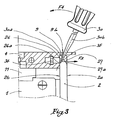
- the electronic card 1 shown in the figures is equipped with a front face 2 and connection means 3. It is intended to be placed in a housing 4 whose rear face 5 is equipped with connection means 6 adapted to cooperate with the means 3.
- the housing 4 is provided on its front face 7 with an opening 8 through which the card 1 is provided to be introduced until the means 3 and 6 cooperate efficiently, the card 1 then having be immobilized in this position.
- the movement of insertion of the card is, essentially, done by pushing the front face 2 towards the rear face 5 of the housing 4, as represented by the arrow F 1 . This movement takes place by sliding the card 1 in two slides 11 and 12, snapped into the upper and lower parts of the housing and provided to receive and guide the top and bottom edges of the card 1.
- the upper and lower edges of the opening 8 are each equipped with a profile 9 or 10 with notches, for example of the type provided by the standard IEEE NE P 1101.10.
- the front face 2 is made of zamack by molding. It is attached to the card 1 by screws, one of which is visible at figure 1 with the reference 22, so that it forms a unitary unit with this map.
- the edge 23 and 24 are respectively noted the upper and lower edges 24 of the front face 2.
- the edge 23 does not extend over the entire width of the front face 2 but is provided with a recess 25 in which are formed two surfaces 26 and 27, inclined with respect to a longitudinal plane P of the portion of the front face 2 containing the edges 23 and 24.
- the surfaces 26 and 27 are formed in the thickness e of the edge 23 recessed by a height h relative to at the edge 23.
- the surfaces 26 and 27 are respectively bordered by a flat strip 26a or 27a, generally perpendicular to surfaces 2 a and 2 b .
- inclined surfaces 28 and 29 are formed near the lower edge 24 of the front face 2, in its thickness, and 28a and 29a are noted flat strips which border.
- the surfaces 26 and 27 are each inclined relative to the plane P by an angle ⁇ of between 30 ° and 45 °, and preferably equal to 35 °.
- the angle ⁇ of inclination of the surfaces 26 and 27 relative to each other is between 61 ° and 90 ° and preferably of the order of 70 °. It is the same for surfaces 28 and 29.
- connection means 3 When the card 1 has been presented in the casing 4 so that its connection means 3 are close to or in contact with the connection means 6, it is necessary to overcome a significant resisting force to engage cooperating means 3 and 6.
- a high degree of leverage is achieved by the screwdriver 30 to the extent that the edge 9b of the notch 9a is close to the face 27 while the shank 30b of the screw may have a relatively large length. Therefore, the force F 3 can be intense, and in particular sufficient to overcome the reaction forces opposing the connection of the means 3 and 6.
- the surfaces 26 to 29 are coplanar with the map 1, which is which implies that the transmission of the force between the screwdriver 30 and the card 1 takes place globally in the plane of the card, no torsion force being created at the front face 2.
- the effort F 3 is coplanar with the upper and lower edges of the card 1, which facilitates their sliding in the slides 11 and 12.
- the effort exerted by the user on the screwdriver 30 can be relatively modest.
- an orifice 31 is provided on the front face 2 for the passage of a fixing screw 32 on the edge 8a of the opening 8, the screw 32 being intended to penetrate into a tapping 33 provided for this purpose in a bar 34 maintained in position in the profile 9 by returns 9 c shaped by spinning on the profile.
- the orifice 31 of the front face 2 remains permanently visible to the operator who is not embarrassed to operate the screw 32, and to visually check its tightening.
- the screwdriver 30 When it is necessary to extract the card 1 from the casing 4, the screwdriver 30 is used as shown in FIG. figure 3 where its stem 30 b abuts against the edge 9b of the notch 9a of the side of the inner volume of the casing 4 so that its end 30 has is pressed against the surface 26.
- a tilting or pivoting of the screwdriver 30, represented by the arrow F 4 has the effect of generating on the surface 26 a force, represented by the arrow F 5 , sufficient to overcome the friction generated at the connection means 3 and 6 at the beginning of the extraction of the card 1 from the housing 4.
- the figure 3 2 shows the front in the mounted position of the card 1 and it is noted that the edge 35 which is common to the surfaces 26 and 27 is arranged substantially facing the internal edge 9 b of the notch 9a, the side of the internal volume of the housing 4, so that in this position, the screwdriver can be introduced to cooperate with the surface 26 or the surface 27 depending on the direction of the desired effort, for insertion or for the extraction of the map 1.
- the edge 35 is rounded to facilitate the establishment "blind" to the end 30 a, in the position of the figure 2 or in that of the figure 3 .
- the method described above can be implemented at the upper edges 23 and lower 24 in according to the environment of the card 1.
- the casing 4 comprises two rows of superposed cards, it is possible to intervene with a screwdriver on the upper edge of the front face of a card of the upper row and on the lower edge of the front of a card in the lower row.
- the surfaces 26 to 29 and the strips 26 a to 29 a are formed in the thickness of the edges 23 and 24 slightly set back relative thereto, so that they are protected during maneuvers of the map to the outside the case and that they will not be damaged. These inclined surfaces are obtained during the molding of the front face 2 and they do not change the unit cost of such a front face.
- two side faces 36 and 37 are created respectively in the vicinity of the surfaces 26 and 27 and in the vicinity of the surfaces 28 and 29, perpendicular to the edges 23 and 24. These faces 36 and 37 possible to guide the end 30 a of the screw 30 by preventing a positioning across said end.
- the invention has the particular advantage of being compatible with all housings equipped with slot profile, regardless of the type of connection means 3 or 6 and their number, which allows a high standardization.
- the invention makes it possible to integrate on the surface 2b devices that comply with the standards in force, such as a coding system, a final centering device and a static discharge means without significant extra cost since these devices can be created by adding or removing material, while the front face 2 is monobloc.
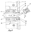
- a specific tool 40 is used to access the surfaces 26 and 27 of the front face 2 of a card installed in the lower case 4 'or the lower surfaces 28 and 29 of a front face 2 of a card installed in the upper casing 4.
- the tool 40 comprises an end 40 similar to that of the screwdriver 30 shown in figures 2 and 3 but its stem 40 b is bent at right angles.
- the angle of bending of the rod 40 b is adapted taking into account the height H of the gap between the casings 4 and 4 '.
- the handling of the cards associated with the front faces 2 takes place mainly by an action at the intervals between the different housings, which is advantageous when the upper and lower housings are in abutment against the upper or lower faces of a cabinet or chest, so that it is not possible to access the upper edge of a card placed in an upper case and the lower edge of a card placed in a lower case.
- bearing surfaces 26-29 planar, that is to say adapted to the shape of the end 30 a of the screw 30 which depends on the shape of the head of the screw 32. If another actuator is used, for example a Phillips screwdriver, the geometry of the bearing surfaces can be adapted accordingly, these surfaces can be concave.
- the invention is applicable to all types of electronic cards intended to be mounted in a housing, fixed or mobile, including a drawer, a cabinet or a chest.
Landscapes
- Engineering & Computer Science (AREA)
- Microelectronics & Electronic Packaging (AREA)
- Casings For Electric Apparatus (AREA)
- Coupling Device And Connection With Printed Circuit (AREA)
- Details Of Connecting Devices For Male And Female Coupling (AREA)
- Mounting Of Printed Circuit Boards And The Like (AREA)
- Burglar Alarm Systems (AREA)
- Brushes (AREA)
Claims (9)
- Frontseite (2) einer Elektronikkarte (1), die vorgesehen ist, um durch eine Öffnung (8) hindurch in ein Gehäuse (4) eingesetzt zu werden, von der mindestens ein Rand mit einem Profil mit Einschnitten (9, 10) ausgestattet ist, dadurch gekennzeichnet, dass sie zwei Auflageflächen (26, 27 - 28, 29) enthält, die in zwei verschiedene Richtungen bezüglich einer Längsebene (P) der Frontseite (2) geneigt sind (a), wobei die zwei Auflageflächen auf einem Teil (23, 24) der Frontseite vorgesehen sind, der in der Nähe des Profils angeordnet ist, wenn die Elektronikkarte in das Gehäuse (4) installiert ist, wobei die zwei Auflageflächen (26-29) mit einem Betätigungsorgan (30) zusammenwirken können, das durch einen der Einschnitte (9a) hindurch eingeführt wird, wobei eine (27, 29) der Auflageflächen mit dem Betätigungsorgan (30) zum Einsetzen (F2, F3) der Karte (1) in das Gehäuse zusammenwirken kann, während die andere Fläche (26, 28) mit dem Betätigungsorgan zum Herausziehen (F4, F5) der Karte zusammenwirken kann.
- Frontseite nach Anspruch 1, dadurch gekennzeichnet, dass die zwei Auflageflächen (26-29) zueinander um einen Winkel (β) geneigt sind, der zwischen 60° und 90°, vorzugsweise in der Größenordnung von 70° liegt.
- Frontseite nach Anspruch 2, dadurch gekennzeichnet, dass die Auflageflächen (26-29) bezüglich der Frontseite (2) so bemessen und positioniert sind, dass ein den Auflageflächen gemeinsamer Rand (34) in der in das Gehäuse (4) montierten Konfiguration der Karte (1) im Wesentlichen gegenüber dem Innenrand (9b) eines Einschnitts (9a) des Profils (9, 10) angeordnet ist.
- Frontseite nach einem der vorhergehenden Ansprüche, dadurch gekennzeichnet, dass sie mindestens eine Auflagefläche (26-29) an jedem ihrer Enden (23, 24) enthält.
- Frontseite nach einem der vorhergehenden Ansprüche, dadurch gekennzeichnet, dass die Auflagefläche (26-29) beim Formen der Frontseite (2) gebildet wird.
- Frontseite nach einem der vorhergehenden Ansprüche, dadurch gekennzeichnet, dass die Auflagefläche (26-29) leicht von einem oberen (23) oder unteren Rand (24) der Frontseite rückversetzt (h) in der Dicke (e) der Frontseite (2) angeordnet ist.
- Elektronikkarte (1), die dazu bestimmt ist, in ein Gehäuse (4) eingesetzt zu werden, dadurch gekennzeichnet, dass sie mit einer Frontseite (2) nach einem der vorhergehenden Ansprüche ausgestattet ist.
- Verfahren zum Einführen oder zur Entnahme einer Elektronikkarte (1) nach Anspruch 7 in ein oder aus einem Gehäuse (4) durch eine Öffnung (8) hindurch, von der mindestens ein Rand mit einem Profil mit Einschnitten (9, 10) ausgestattet ist, dadurch gekennzeichnet, dass es darin besteht, ein Betätigungsorgan (30) durch einen der Einschnitte (9a) des Profils hindurch einzuführen, das Organ gegen eine Auflagefläche (26-29) anzulegen, die in einem Teil (23, 24) der Frontseite (2) der Karte ausgebildet ist, der dazu bestimmt ist, in der Nähe des Profils angeordnet zu werden, und eine Schwenkkraft (F2, F4) des Betätigungsorgans bezüglich seiner Auflagezone (30b) auf einem Rand (9b) der Einkerbung auszuüben, so dass eine Kraft (F3, F5) auf die Frontseite in Höhe der Auflagefläche in einer Richtung ausgeübt wird, die dem Einführen oder Herausnehmen der Karte entspricht.
- Verfahren nach Anspruch 8, dadurch gekennzeichnet, dass es darin besteht, als Betätigungsorgan einen Schraubendreher (30) zur Betätigung einer Befestigungsschraube (32) der Karte (1) im Gehäuse (4) zu verwenden.
Applications Claiming Priority (2)
| Application Number | Priority Date | Filing Date | Title |
|---|---|---|---|
| FR9909201A FR2796520B1 (fr) | 1999-07-12 | 1999-07-12 | Face avant de carte electronique, carte electronique et procede d'insertion et d'extraction d'une telle carte dans un boitier |
| FR9909201 | 1999-07-12 |
Publications (2)
| Publication Number | Publication Date |
|---|---|
| EP1069813A1 EP1069813A1 (de) | 2001-01-17 |
| EP1069813B1 true EP1069813B1 (de) | 2011-01-05 |
Family
ID=9548148
Family Applications (1)
| Application Number | Title | Priority Date | Filing Date |
|---|---|---|---|
| EP00401861A Expired - Lifetime EP1069813B1 (de) | 1999-07-12 | 2000-06-29 | Frontplatte für eine elektronische Baugruppe, elektronische Baugruppe, und deren Einschub- oder Ausziehverfahren aus einem Baugruppenträger |
Country Status (14)
| Country | Link |
|---|---|
| US (1) | US6442034B1 (de) |
| EP (1) | EP1069813B1 (de) |
| JP (1) | JP2001044650A (de) |
| KR (1) | KR100725569B1 (de) |
| CN (1) | CN1195344C (de) |
| AT (1) | ATE494765T1 (de) |
| AU (1) | AU759799B2 (de) |
| BR (1) | BR0002712B1 (de) |
| CA (1) | CA2314768C (de) |
| DE (1) | DE60045462D1 (de) |
| FR (1) | FR2796520B1 (de) |
| MX (1) | MXPA00006786A (de) |
| RU (1) | RU2242099C2 (de) |
| TW (1) | TW488114B (de) |
Families Citing this family (2)
| Publication number | Priority date | Publication date | Assignee | Title |
|---|---|---|---|---|
| US20050193539A1 (en) * | 2004-03-02 | 2005-09-08 | Payne Robert D. | Molding remover system |
| CN108321569B (zh) * | 2018-01-24 | 2019-08-02 | Oppo广东移动通信有限公司 | 电子设备及其电路板组件 |
Family Cites Families (21)
| Publication number | Priority date | Publication date | Assignee | Title |
|---|---|---|---|---|
| US2976510A (en) * | 1957-05-02 | 1961-03-21 | Sperry Rand Corp | Wrench for printed circuit card library rack |
| UST876004I4 (en) * | 1969-12-29 | 1970-07-28 | Circuit board attachment | |
| IT1067178B (it) * | 1976-07-07 | 1985-03-12 | Sits Soc It Telecom Siemens | Estrattore inseritore per piastre a circuito stampato |
| JPS53128888U (de) * | 1977-03-23 | 1978-10-13 | ||
| US4313150A (en) * | 1979-09-24 | 1982-01-26 | Northern Telecom Limited | Latching lever for printed circuit boards |
| US4307510A (en) * | 1980-03-12 | 1981-12-29 | The United States Of America As Represented By The Administrator Of The National Aeronautics & Space Administration | Computer circuit card puller |
| SU1192174A1 (ru) * | 1984-05-30 | 1985-11-15 | Предприятие П/Я М-5339 | Радиоэлектронный блок |
| US4648009A (en) * | 1986-04-09 | 1987-03-03 | Northern Telecom Limited | Articulated latch for use with a printed circuit board |
| FR2599927A1 (fr) * | 1986-06-06 | 1987-12-11 | Alsthom Cgee | Facade modulaire demontable pour caisson d'equipement technique notamment electronique |
| SU1499537A1 (ru) * | 1988-01-28 | 1989-08-07 | И.А.Горбань | Корпус радиоэлектронной аппаратуры дл размещени и фиксации печатных плат |
| RU2047949C1 (ru) * | 1991-01-30 | 1995-11-10 | Штенников Валерий Юрьевич | Вставной радиоэлектронный блок |
| US5268821A (en) * | 1991-03-06 | 1993-12-07 | Tandem Computers Incorporated | Shared pc board ejector/injector tool |
| JP2557579B2 (ja) * | 1991-07-24 | 1996-11-27 | 東北日本電気株式会社 | 電子回路パッケージ用挿抜装置 |
| US5225962A (en) * | 1992-03-11 | 1993-07-06 | Square D Company | Distribution board with rear electrical access |
| JPH0779198B2 (ja) * | 1993-04-16 | 1995-08-23 | 日本電気株式会社 | スタッキング・コネクタの着脱構造 |
| DE4428529C1 (de) * | 1994-08-12 | 1995-08-24 | Schroff Gmbh | Vorrichtung zum Ausziehen einer Steckbaugruppe |
| FR2743977B1 (fr) * | 1996-01-19 | 1998-02-06 | Gec Alsthom Transport Sa | Tiroir pour cartes electroniques a embrochement et debrochage automatiques et tiroir et son coffre |
| DE29610693U1 (de) * | 1996-06-18 | 1997-07-17 | Siemens AG, 80333 München | Baugruppenträger mit zentrierbaren Frontplatten aufweisenden, einsteckbaren Baugruppen |
| US5793614A (en) * | 1996-09-03 | 1998-08-11 | Tektronix, Inc. | Injector/ejector for electronic module housing |
| US6003689A (en) * | 1998-03-18 | 1999-12-21 | 3Com Corporation | PCB ejector cage assembly |
| US6216339B1 (en) * | 1998-05-08 | 2001-04-17 | 3Com Corporation | Tool-actuated ejector mechanism for extracting electronic modular components |
-
1999
- 1999-07-12 FR FR9909201A patent/FR2796520B1/fr not_active Expired - Fee Related
-
2000
- 2000-06-29 DE DE60045462T patent/DE60045462D1/de not_active Expired - Lifetime
- 2000-06-29 AT AT00401861T patent/ATE494765T1/de not_active IP Right Cessation
- 2000-06-29 EP EP00401861A patent/EP1069813B1/de not_active Expired - Lifetime
- 2000-07-06 TW TW089113438A patent/TW488114B/zh not_active IP Right Cessation
- 2000-07-07 US US09/612,361 patent/US6442034B1/en not_active Expired - Lifetime
- 2000-07-10 JP JP2000207663A patent/JP2001044650A/ja not_active Ceased
- 2000-07-10 MX MXPA00006786A patent/MXPA00006786A/es unknown
- 2000-07-10 AU AU45149/00A patent/AU759799B2/en not_active Expired
- 2000-07-11 BR BRPI0002712-0B1A patent/BR0002712B1/pt not_active IP Right Cessation
- 2000-07-11 CA CA002314768A patent/CA2314768C/fr not_active Expired - Lifetime
- 2000-07-11 RU RU2000118674/09A patent/RU2242099C2/ru active
- 2000-07-11 KR KR1020000039479A patent/KR100725569B1/ko not_active Expired - Lifetime
- 2000-07-12 CN CNB001204947A patent/CN1195344C/zh not_active Expired - Lifetime
Also Published As
| Publication number | Publication date |
|---|---|
| ATE494765T1 (de) | 2011-01-15 |
| MXPA00006786A (es) | 2002-06-04 |
| CN1195344C (zh) | 2005-03-30 |
| FR2796520B1 (fr) | 2001-09-07 |
| HK1033390A1 (en) | 2001-08-24 |
| TW488114B (en) | 2002-05-21 |
| EP1069813A1 (de) | 2001-01-17 |
| CA2314768A1 (fr) | 2001-01-12 |
| BR0002712B1 (pt) | 2013-12-31 |
| KR100725569B1 (ko) | 2007-06-08 |
| RU2242099C2 (ru) | 2004-12-10 |
| CA2314768C (fr) | 2009-02-03 |
| BR0002712A (pt) | 2001-03-13 |
| FR2796520A1 (fr) | 2001-01-19 |
| JP2001044650A (ja) | 2001-02-16 |
| AU4514900A (en) | 2001-01-18 |
| KR20010015274A (ko) | 2001-02-26 |
| DE60045462D1 (de) | 2011-02-17 |
| AU759799B2 (en) | 2003-05-01 |
| US6442034B1 (en) | 2002-08-27 |
| CN1282992A (zh) | 2001-02-07 |
Similar Documents
| Publication | Publication Date | Title |
|---|---|---|
| CA2002181A1 (fr) | Recepteur de cartes a puce | |
| EP0123590A1 (de) | Verbinder | |
| EP0515897A1 (de) | Kontaktgeber für Karten mit Schaltkreis | |
| EP1026712B1 (de) | Anlage mit einem elektrischen Schalter und Verriegelung durch einen Kabel | |
| EP2654137A1 (de) | Sockel eines Multikontaktanschlusses zum Schnellbefestigen auf einer Platte und entsprechendes Montage-/Demontage-Verfahren | |
| FR2702887A1 (fr) | Appareil électrique, en particulier bloc de jonction, à borne de connexion à connexion rapide. | |
| EP1729376A2 (de) | Verriegelungshebelmechanismus für Verbinder | |
| EP0542594A1 (de) | Modulare elektronische Einheit | |
| EP0287417B1 (de) | Einrichtung zum Lesen/Schreiben elektronischer Speicherkarten, geschützt gegen Zerstörungswut | |
| EP0596776B1 (de) | Kontaktleiste mit anpassbarer Etikettierung | |
| EP1069813B1 (de) | Frontplatte für eine elektronische Baugruppe, elektronische Baugruppe, und deren Einschub- oder Ausziehverfahren aus einem Baugruppenträger | |
| EP0785606A1 (de) | Vorrichtung zum Befestigen eines elektrischen Gerätes | |
| EP1106774B1 (de) | Vorrichtung zum Fixieren eines Antriebs, und Betätigungsmechanismus einer Schliess- oder Sonnenschutzeinrichtung mit solcher Vorrichtung | |
| FR2782816A1 (fr) | Connecteur de lecteur de carte sim | |
| FR2544158A1 (fr) | Dispositif d'assemblage pour systeme d'ordinateur | |
| EP3840136B1 (de) | Mechanismus eines elektrischen geräts, entsprechende elektrische anordung und entsprechendes elektrisches gerät | |
| EP3081061B1 (de) | Gehäuse für mindestens eine elektronische karte | |
| EP2190275A1 (de) | Gehäuse für ein elektronisches Modul zur Steuerung einer Maschine | |
| EP0744088A1 (de) | Elektrische stecker in englischer ausführung | |
| EP4023830B1 (de) | Verriegelungssystem mit clip für bodenplatte | |
| EP2257145B1 (de) | Verbindungsvorrichtung | |
| FR2567689A1 (fr) | Pince a denuder | |
| FR2503771A1 (fr) | Appareil propre a la mise en place de crochets pour elements de couverture, en particulier ardoises | |
| FR2760774A1 (fr) | Cle non reproductible pour serrure a gorges | |
| WO2025078894A1 (fr) | Système d'alimentation et d'entraînement pour un tambour, dispositif d'enroulement de câble le comportant et ensemble drone filaire ou rendu filaire et base |
Legal Events
| Date | Code | Title | Description |
|---|---|---|---|
| PUAI | Public reference made under article 153(3) epc to a published international application that has entered the european phase |
Free format text: ORIGINAL CODE: 0009012 |
|
| AK | Designated contracting states |
Kind code of ref document: A1 Designated state(s): AT BE CH CY DE DK ES FI FR GB GR IE IT LI LU MC NL PT SE |
|
| AX | Request for extension of the european patent |
Free format text: AL;LT;LV;MK;RO;SI |
|
| 17P | Request for examination filed |
Effective date: 20010717 |
|
| AKX | Designation fees paid |
Free format text: AT BE CH CY DE DK ES FI FR GB GR IE IT LI LU MC NL PT SE |
|
| RAP1 | Party data changed (applicant data changed or rights of an application transferred) |
Owner name: ALSTOM |
|
| RTI1 | Title (correction) |
Free format text: ELECTRONIC CARD FRONT PLATE, ELECTRONIC PLATE AND ITS INSERTING AND EXTRACTING METHOD IN A RACK |
|
| 17Q | First examination report despatched |
Effective date: 20071213 |
|
| RAP1 | Party data changed (applicant data changed or rights of an application transferred) |
Owner name: ALSTOM TRANSPORT SA |
|
| RTI1 | Title (correction) |
Free format text: ELECTRONIC CARD FRONT PLATE, ELECTRONIC PLATE AND ITS INSERTING OR EXTRACTING METHOD IN A RACK |
|
| GRAP | Despatch of communication of intention to grant a patent |
Free format text: ORIGINAL CODE: EPIDOSNIGR1 |
|
| GRAS | Grant fee paid |
Free format text: ORIGINAL CODE: EPIDOSNIGR3 |
|
| GRAA | (expected) grant |
Free format text: ORIGINAL CODE: 0009210 |
|
| AK | Designated contracting states |
Kind code of ref document: B1 Designated state(s): AT BE CH CY DE DK ES FI FR GB GR IE IT LI LU MC NL PT SE |
|
| REG | Reference to a national code |
Ref country code: GB Ref legal event code: FG4D Free format text: NOT ENGLISH |
|
| REG | Reference to a national code |
Ref country code: CH Ref legal event code: EP |
|
| REG | Reference to a national code |
Ref country code: IE Ref legal event code: FG4D Free format text: LANGUAGE OF EP DOCUMENT: FRENCH |
|
| REF | Corresponds to: |
Ref document number: 60045462 Country of ref document: DE Date of ref document: 20110217 Kind code of ref document: P |
|
| REG | Reference to a national code |
Ref country code: DE Ref legal event code: R096 Ref document number: 60045462 Country of ref document: DE Effective date: 20110217 |
|
| REG | Reference to a national code |
Ref country code: NL Ref legal event code: T3 |
|
| PG25 | Lapsed in a contracting state [announced via postgrant information from national office to epo] |
Ref country code: ES Free format text: LAPSE BECAUSE OF FAILURE TO SUBMIT A TRANSLATION OF THE DESCRIPTION OR TO PAY THE FEE WITHIN THE PRESCRIBED TIME-LIMIT Effective date: 20110416 Ref country code: GR Free format text: LAPSE BECAUSE OF FAILURE TO SUBMIT A TRANSLATION OF THE DESCRIPTION OR TO PAY THE FEE WITHIN THE PRESCRIBED TIME-LIMIT Effective date: 20110406 Ref country code: PT Free format text: LAPSE BECAUSE OF FAILURE TO SUBMIT A TRANSLATION OF THE DESCRIPTION OR TO PAY THE FEE WITHIN THE PRESCRIBED TIME-LIMIT Effective date: 20110505 Ref country code: SE Free format text: LAPSE BECAUSE OF FAILURE TO SUBMIT A TRANSLATION OF THE DESCRIPTION OR TO PAY THE FEE WITHIN THE PRESCRIBED TIME-LIMIT Effective date: 20110105 |
|
| REG | Reference to a national code |
Ref country code: IE Ref legal event code: FD4D |
|
| PG25 | Lapsed in a contracting state [announced via postgrant information from national office to epo] |
Ref country code: AT Free format text: LAPSE BECAUSE OF FAILURE TO SUBMIT A TRANSLATION OF THE DESCRIPTION OR TO PAY THE FEE WITHIN THE PRESCRIBED TIME-LIMIT Effective date: 20110105 Ref country code: FI Free format text: LAPSE BECAUSE OF FAILURE TO SUBMIT A TRANSLATION OF THE DESCRIPTION OR TO PAY THE FEE WITHIN THE PRESCRIBED TIME-LIMIT Effective date: 20110105 Ref country code: CY Free format text: LAPSE BECAUSE OF FAILURE TO SUBMIT A TRANSLATION OF THE DESCRIPTION OR TO PAY THE FEE WITHIN THE PRESCRIBED TIME-LIMIT Effective date: 20110105 |
|
| PG25 | Lapsed in a contracting state [announced via postgrant information from national office to epo] |
Ref country code: IE Free format text: LAPSE BECAUSE OF FAILURE TO SUBMIT A TRANSLATION OF THE DESCRIPTION OR TO PAY THE FEE WITHIN THE PRESCRIBED TIME-LIMIT Effective date: 20110105 Ref country code: DK Free format text: LAPSE BECAUSE OF FAILURE TO SUBMIT A TRANSLATION OF THE DESCRIPTION OR TO PAY THE FEE WITHIN THE PRESCRIBED TIME-LIMIT Effective date: 20110105 |
|
| PLBE | No opposition filed within time limit |
Free format text: ORIGINAL CODE: 0009261 |
|
| STAA | Information on the status of an ep patent application or granted ep patent |
Free format text: STATUS: NO OPPOSITION FILED WITHIN TIME LIMIT |
|
| 26N | No opposition filed |
Effective date: 20111006 |
|
| BERE | Be: lapsed |
Owner name: ALSTOM TRANSPORT SA Effective date: 20110630 |
|
| REG | Reference to a national code |
Ref country code: CH Ref legal event code: PL |
|
| REG | Reference to a national code |
Ref country code: DE Ref legal event code: R097 Ref document number: 60045462 Country of ref document: DE Effective date: 20111006 |
|
| GBPC | Gb: european patent ceased through non-payment of renewal fee |
Effective date: 20110629 |
|
| PG25 | Lapsed in a contracting state [announced via postgrant information from national office to epo] |
Ref country code: BE Free format text: LAPSE BECAUSE OF NON-PAYMENT OF DUE FEES Effective date: 20110630 |
|
| PG25 | Lapsed in a contracting state [announced via postgrant information from national office to epo] |
Ref country code: LI Free format text: LAPSE BECAUSE OF NON-PAYMENT OF DUE FEES Effective date: 20110630 Ref country code: CH Free format text: LAPSE BECAUSE OF NON-PAYMENT OF DUE FEES Effective date: 20110630 |
|
| PG25 | Lapsed in a contracting state [announced via postgrant information from national office to epo] |
Ref country code: GB Free format text: LAPSE BECAUSE OF NON-PAYMENT OF DUE FEES Effective date: 20110629 |
|
| PG25 | Lapsed in a contracting state [announced via postgrant information from national office to epo] |
Ref country code: MC Free format text: LAPSE BECAUSE OF NON-PAYMENT OF DUE FEES Effective date: 20110630 |
|
| PG25 | Lapsed in a contracting state [announced via postgrant information from national office to epo] |
Ref country code: LU Free format text: LAPSE BECAUSE OF NON-PAYMENT OF DUE FEES Effective date: 20110629 |
|
| REG | Reference to a national code |
Ref country code: FR Ref legal event code: TP Owner name: ALSTOM TRANSPORT TECHNOLOGIES, FR Effective date: 20141209 |
|
| REG | Reference to a national code |
Ref country code: DE Ref legal event code: R081 Ref document number: 60045462 Country of ref document: DE Owner name: ALSTOM TRANSPORT TECHNOLOGIES, FR Free format text: FORMER OWNER: ALSTOM TRANSPORT SA, LEVALLOIS-PERRET, FR |
|
| REG | Reference to a national code |
Ref country code: NL Ref legal event code: PD Owner name: ALSTOM TRANSPORT TECHNOLOGIES; FR Free format text: DETAILS ASSIGNMENT: VERANDERING VAN EIGENAAR(S), OVERDRACHT; FORMER OWNER NAME: ALSTOM TRANSPORT SA Effective date: 20150904 |
|
| REG | Reference to a national code |
Ref country code: FR Ref legal event code: PLFP Year of fee payment: 17 |
|
| REG | Reference to a national code |
Ref country code: FR Ref legal event code: PLFP Year of fee payment: 18 |
|
| REG | Reference to a national code |
Ref country code: DE Ref legal event code: R081 Ref document number: 60045462 Country of ref document: DE Owner name: ALSTOM TRANSPORT TECHNOLOGIES, FR Free format text: FORMER OWNER: ALSTOM TRANSPORT TECHNOLOGIES, LEVALLOIS-PERRET, FR |
|
| REG | Reference to a national code |
Ref country code: FR Ref legal event code: CA Effective date: 20180103 |
|
| REG | Reference to a national code |
Ref country code: FR Ref legal event code: PLFP Year of fee payment: 19 |
|
| PGFP | Annual fee paid to national office [announced via postgrant information from national office to epo] |
Ref country code: DE Payment date: 20190619 Year of fee payment: 20 Ref country code: NL Payment date: 20190619 Year of fee payment: 20 Ref country code: IT Payment date: 20190624 Year of fee payment: 20 |
|
| PGFP | Annual fee paid to national office [announced via postgrant information from national office to epo] |
Ref country code: FR Payment date: 20190619 Year of fee payment: 20 |
|
| REG | Reference to a national code |
Ref country code: DE Ref legal event code: R071 Ref document number: 60045462 Country of ref document: DE |
|
| REG | Reference to a national code |
Ref country code: NL Ref legal event code: MK Effective date: 20200628 |