EP1070468A1 - Vorrichtung zum Auftragen eines Mittels auf Wimpern oder Augenbrauen - Google Patents
Vorrichtung zum Auftragen eines Mittels auf Wimpern oder Augenbrauen Download PDFInfo
- Publication number
- EP1070468A1 EP1070468A1 EP00402092A EP00402092A EP1070468A1 EP 1070468 A1 EP1070468 A1 EP 1070468A1 EP 00402092 A EP00402092 A EP 00402092A EP 00402092 A EP00402092 A EP 00402092A EP 1070468 A1 EP1070468 A1 EP 1070468A1
- Authority
- EP
- European Patent Office
- Prior art keywords
- base
- elements
- teeth
- individual elements
- row
- Prior art date
- Legal status (The legal status is an assumption and is not a legal conclusion. Google has not performed a legal analysis and makes no representation as to the accuracy of the status listed.)
- Granted
Links
Images






Classifications
-
- A—HUMAN NECESSITIES
- A46—BRUSHWARE
- A46B—BRUSHES
- A46B9/00—Arrangements of the bristles in the brush body
- A46B9/02—Position or arrangement of bristles in relation to surface of the brush body, e.g. inclined, in rows, in groups
- A46B9/023—Position or arrangement of bristles in relation to surface of the brush body, e.g. inclined, in rows, in groups arranged like in hair brushes, e.g. hair treatment, dyeing, streaking
-
- A—HUMAN NECESSITIES
- A45—HAND OR TRAVELLING ARTICLES
- A45D—HAIRDRESSING OR SHAVING EQUIPMENT; EQUIPMENT FOR COSMETICS OR COSMETIC TREATMENTS, e.g. FOR MANICURING OR PEDICURING
- A45D40/00—Casings or accessories specially adapted for storing or handling solid or pasty toiletry or cosmetic substances, e.g. shaving soaps or lipsticks
- A45D40/26—Appliances specially adapted for applying pasty paint, e.g. using roller, using a ball
- A45D40/262—Appliances specially adapted for applying pasty paint, e.g. using roller, using a ball using a brush or the like
- A45D40/265—Appliances specially adapted for applying pasty paint, e.g. using roller, using a ball using a brush or the like connected to the cap of the container
-
- A—HUMAN NECESSITIES
- A46—BRUSHWARE
- A46B—BRUSHES
- A46B2200/00—Brushes characterized by their functions, uses or applications
- A46B2200/10—For human or animal care
- A46B2200/1046—Brush used for applying cosmetics
- A46B2200/1053—Cosmetics applicator specifically for mascara
- A46B2200/106—Cosmetics applicator specifically for mascara including comb like element
Definitions
- the present invention relates to an applicator for applying a product, such as than a cosmetic product, for example, on keratin fibers such as the eyelashes or eyebrows.
- the invention also relates to an application assembly comprising a applicator and a container for containing the product to be applied.
- the product to be applied is a mascara containing fibers
- an applicator comprising an application element capable align the fibers in such a way that they have a substantially orientation parallel to the lashes when the product is applied.
- the new device comprises a rod and an element application at one end of the rod, this application element comprising a base and at least two protruding elements connecting to the base and is characterized by the fact that said projecting elements are each connected to the base along an axis extending substantially in the extension of a corresponding side of the base when the latter has a polygonal cross section or substantially tangential to the base when it has a non-polygonal cross section.
- the axis of the protruding element extends substantially in a perpendicular plane to the longitudinal direction of the base.
- the axis of the projecting element also extends from the portion of the element in projection which joins the base to a free end of the projecting element.
- the applicator comprises an element Application having a base of polygonal cross section, having a plurality of sides and a plurality of projecting elements arranged on the base. At least two elements projecting extend from the base substantially in the continuation of different sides from the base and in different directions.
- the arrangement of the projecting elements on the base facilitates the coming of the eyelashes to the contact of the latter, which may have a perfectly defined surface condition, this which is not always the case with a conventional brush of the twisted core type.
- the eyelashes can be loaded with product on contact with the base.
- the base can thus participate actively in the application of the product. on the eyelashes thanks to the particular arrangement of the projecting elements in the invention, which offers more freedom in the choice and arrangement of these.
- a protruding element within the meaning of the present invention may correspond to or include a row of individual elements or reliefs, which can be arranged multiple ways.
- the applicator advantageously makes it possible to produce such individual elements with a small spacing between two consecutive individual elements within each row.
- projecting elements or “elements individual” may correspond, for example, to bristles or teeth.
- the teeth or bristles can be initially separated from the base and fixed to this last to form the application element.
- the teeth or bristles can be made in one piece with the base, for example by molding.
- the applicator has at least two projecting elements oriented in the same gyratory direction around the longitudinal axis of the base.
- the projecting elements can be either substantially parallel or substantially non-parallel.
- the base may have a substantially constant cross section at less over a portion of its length, all of the individual elements in a row located on this portion, preferably of each row, extending substantially in the extension of the corresponding side of the base when it has a cross-section polygonal.
- the base may have a variable cross section, with substantially a regular or irregular polygon profile, preferably regular, for example triangular, square, pentagonal, hexagonal or octagonal, the faces corresponding to the sides of the base may be flat or slightly concave or convex.
- the base When the base has a non-polygonal cross-section, it can be circular or elliptical for example.
- the device can allow the combing of eyelashes or eyebrows and has at least one row of consecutive individual elements comprising a succession of consecutive individual elements at least partially shifted alternately on either side of a geometric separation surface.
- the individual elements can be teeth.
- Portions of at least two consecutive individual elements in the row consecutive individual elements may be substantially aligned.
- substantially aligned should be understood as meaning that part of each of the substantially aligned portions of the individual elements is arranged on a first side of a line passing through the portions of the consecutive individual elements in question and another part of each of the portions aligned consecutive elements is arranged on a second side of the line, opposite the first side, this line being substantially parallel to a longitudinal axis of the row consecutive individual elements.
- An example of such an embodiment with portions "substantially aligned” corresponds to consecutive individual elements arranged in such a way so that a straight line goes through the centers of each of the hases of the elements consecutive individual, especially when the elements are teeth.
- other realizations can be envisaged.
- At least two consecutive individual elements can have substantially contiguous parts.
- the expression “substantially contiguous” can be understood as meaning that an eyelash is prevented from moving freely through the portions of at least at least two consecutive individual elements in a plane substantially perpendicular to the longitudinal axis of the base, due to the proximity of said portions.
- an eyelash penetrating between two elements consecutive individuals having substantially contiguous portions is prevented from move freely through said portions due to the proximity of said portions and is gripped.
- the portions may be close enough to prevent the passage of an eyelash between them.
- substantially contiguous includes portions contacting or overlapping, these portions are not necessarily in contact, as long as the eyelash is prevented from moving freely between them.
- the choice of the spacing between the substantially contiguous parts may result various considerations, including the average diameter of an eyelash and the nature of the product applied.
- the substantially contiguous parts allow to grab an eyelash.
- This grip makes it possible to distribute the product in a substantially uniform over substantially the entire length of an eyelash.
- the gripping of the eyelashes by the substantially contiguous parts also allows to reorganize the eyelashes by moving the applicator. For example, when the eyelashes are gripped, the movement, in particular in rotation, of the applicator can make it possible to resort.
- overlapping should be understood to mean that the two overlapping portions overlap when the applicator element is observed from side or front or, at the limit, overlap only by an edge or a point of contact.
- the substantially contiguous portions may have overlapping faces, extending either perpendicular to the longitudinal axis of the base (or of the row elements) or substantially parallel to the longitudinal axis of the base (or of the row of elements).
- At least one gap preferably a V-shaped groove or notch, can be formed between consecutive individual elements having parts substantially contiguous.
- At least two consecutive individual elements may have parts either diverging away from each other, or converging towards the other, either which cross or extend substantially parallel to one another.
- At least two consecutive individual elements can have parts upper ones directed towards opposite ends of the base.
- the aforementioned geometric separation surface preferably passes through the centers of the bases of the substantially aligned individual elements.
- the basics are preferably parallel and their height can be for example greater than or equal to 0.2 mm about.
- the individual elements are teeth, these can be made with a small gap at their base so that the eyelashes can be gripped effectively between two consecutive teeth, while having more spacing important between their free ends, this spacing promoting the engagement of the eyelashes between the teeth and the creation of product reserves on the application element.
- the geometric separation surface can be a plane.
- the geometric separation surface is advantageously a joint plane for molding the application element.
- the geometric separation surface can also be a surface cylindrical whose directrix is a curve or a broken line.
- the geometric separation surface can also be a non-planar surface, for example twisted or helical.
- the geometric separation surface is a plane aligning the substantially aligned portions of at least two consecutive teeth.
- the application element comprises elements individual in the form of teeth having hases whose depth is greater than the width.
- a relatively high depth gives the individual elements a good mechanical resistance to the forces exerted by the eyelashes on the device.
- the ratio b / e is for example greater than or equal to 1.2, or even greater than or equal at 1.4, b being the depth of the base of a tooth and e its width.
- the b / c ratio is for example greater than or equal to 1.2, or even greater than or equal at 1.4, b being the depth of the base of a tooth and c the interval between two teeth successive offset on the same side of said geometric separation surface.
- the teeth can have a depth which varies according to the axial positioning along the axis of the base.
- the teeth can thus have an increasing, decreasing depth, increasing then decreasing or vice versa, from front to back.
- individual elements can be deeper that the gap between two adjacent individual elements arranged on the same side of the geometric separation surface, the depth being measured in one direction substantially perpendicular to the longitudinal axis of the base and the above-mentioned interval being measured in a direction substantially parallel to the longitudinal axis of the base.
- the device according to the invention comprises at at least one row of individual elements such as teeth whose bases have front and / or rear faces perpendicular to the axis of the base or forming an acute angle or obtuse with this one.
- the row of individual elements can have a first series of elements having faces directed towards one of the ends of the base and being inclined in a direction given with respect to the longitudinal axis of the row, and a second series of elements, alternating with those of the first series, having laces directed towards one of the ends of the base, inclined in a direction different from that of the elements of the first series, relative to the longitudinal axis of the row.
- the device comprises at least one row individual elements comprising a first series of elements whose front faces and / or rear are inclined relative to the axis of the base and a second series of elements the front and / or rear faces of which are inclined in a manner different from that of elements of the first series with respect to the axis of the base, the elements of the first series and those of the second series being arranged alternately at least partially of on either side of a geometric separation surface.
- the application element can comprise at least one individual element having a concave or convex face directed towards one end of the application element.
- At least two individual elements can have a convex face or concave directed towards one end of the application element, one of the two elements may have a concave or convex face directed towards one end of the element of application while the other of the two consecutive elements may have a flat face directed towards one end of the applicator element.
- three individual elements in a row define a volume arranged to contain the product to apply.
- the ratio of the interval separating two individual elements adjacent to the same side of the geometric separation surface at the width of the individual element arranged on the opposite side of the geometric separation surface and located between the adjacent individual elements is between 0.2 and 2 approximately.
- the above-mentioned interval and width are measured substantially halfway up the individual elements.
- each projecting element and the adjacent side of the base, other than the face which the projecting element substantially extends defines a open volume arranged to contain the product to be applied.
- the device comprises at least one succession of teeth offset at least partially alternately on both sides with a geometric separating surface, these teeth having upper parts oriented forward and back respectively.
- the device comprises at least one succession of teeth with upper parts moving away from each other, when the device is viewed from the front.
- the device comprises at least one succession of teeth with upper parts facing each other. when the device is viewed from the front.
- the device comprises at least one succession of teeth arranged so that two adjacent teeth overlap when the device is viewed from the front.
- the device can include at least one row of individual elements comprising a first series of teeth located on one side of the geometric surface of separation and a second set of teeth located on the other side of this surface geometric separation, alternating with the teeth of the first series, the teeth of the first series having their front face, respectively rear, convex or concave towards the front, respectively to the rear, and the teeth of the second series having their face front, respectively rear, concave or convex forward, respectively toward the back.
- the device may also include a row of teeth comprising a first set of teeth located on one side of a geometric separation surface and a second series of teeth located on the other side of this geometric separation surface.
- the teeth of the first series being arranged alternately with the teeth of the second series, the teeth of the first series having their front face, respectively rear, concave or convex forwards, respectively backwards, and the teeth of the second series having their rear face, respectively front, flat.
- two consecutive individual elements when the device is observed in its axis. two consecutive individual elements have free ends which diverge. Alternatively, when the device is observed in its axis, two consecutive individual elements have free ends that converge. In another variant, when the device is observed in its axis, two consecutive individual elements have free ends which intersect or are substantially parallel. So the free ends of the elements individuals in the same row can point in the same direction. When the device is observed in its axis, at least three consecutive individual elements can have free ends that are aligned.
- the projecting elements are advantageously made by molding of material plastic in one piece with the base.
- the device can comprise two parts made with a film hinge and assembled one against the other.
- the base is preferably of substantially elongated shape and the elements in protrusion preferably extend along the base.
- the row of consecutive individual elements preferably extends along the base.
- the base preferably has a uniform cross section on at minus part of its length.
- the base may have a cross section in the shape of a regular polygon or irregular, with one or more sides of the base plane or not planar, for example concave or convex.
- the projecting elements may have a free edge which is crenellated or serrated, the slots or teeth being arranged to grip the eyelashes together.
- the height of the projecting elements can be between 0.5 and 15 mm approximately and preferably between 7 and 13 mm.
- the height of the individual elements can be variable.
- the height of the individual elements can be between 0.5 and 15 mm.
- the device according to the invention when used as an element application, advantageously includes a tapered nose facilitating re-entry into the container.
- This nose may or may not have projecting elements.
- the invention also relates to a packaging device and application comprising a container for containing a reserve of product, an organ and an applicator comprising a rod provided at one end with a device such as above, used for the application.
- the application element may consist of an insert on the rod of the applicator.
- the application element may alternatively be produced by molding of material plastic in one piece with the applicator rod.
- the application element can be produced by molding plastic material from a integral with the applicator rod and with a sealing member intended to ensure a tight closure of the container when not in use, this sealing member being able to present a shaped surface to fit tightly in a neck of the container.
- the base is made of an elastomeric material and the rod in a rigid or semi-rigid plastic, the base being overmolded on the rod or reported on it.
- the fact of making the base and the elements projecting from a material elastomer can facilitate the crossing of the wiper member.
- the rod of the applicator can be made of a material plastic less hard than that used to make the application element.
- a material plastic less hard that used to make the application element.
- We can thus use for manufacturing reasons for example a relatively hard material for create the application element and compensate for the hardness of the application element application time by the flexibility of the rod.
- the applicator element can be removably attached to a part distal end of the stem.
- the longitudinal axis of the applicator element may extend substantially parallel to the longitudinal axis of the rod or may extend at an angle with the longitudinal axis of the rod, and in particular be perpendicular to the longitudinal axis of the rod.
- the wiper member is preferably deformable and may include, for example, a block of foam or an elastomer lip.
- the base may have firm faces and stable.
- the base is made in the form of a single piece made of a in one piece, advantageously by molding.
- Such a solid, unitary structure can prevent eyelashes from passing through the base and reach the longitudinal axis of the base.
- the application element can be devoid of twisted core.
- Projecting elements may extend from the base from locations away from the longitudinal axis of the base.
- the invention also relates to the use of such a device for the eyelash or eyebrow makeup.
- the invention therefore also relates to a method for applying a product to eyelashes, comprising the steps of providing an application element as defined above, to load at least part of the application element with product and to bring at least part of the applicator element into contact with the eyelashes, so that the product is deposited on the eyelashes.
- the application element can be loaded with product by insertion into a container containing the product, then extraction, the excess product being removed from the elements projecting.
- the application element can be loaded with product by dispensing the produced from a container or by bringing the application element into contact with a bread product.
- this product bread can be moistened or the element wet application then brought into contact with solid bread.
- the method further comprises the step consisting in orienting the fibers by means of the application element, so that the fibers are substantially parallel to the eyelashes when the product is applied.
- This alignment of the fibers preferably results from a funneling effect produced by the slots or teeth of the protruding elements or by the spacing between individual elements.
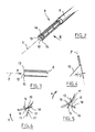
- the packaging and application device 1 shown in FIG. 1 includes a container 2 containing a reserve 3 of a cosmetic product and / or treatment for eyelashes or eyebrows, for example mascara.
- the container 2 is provided with a threaded neck 4 defining an opening.
- the opening of the container 2 is internally provided with a wiping member 5 consisting of a part inserted into the neck 4, having a lip in the lower part elastically deformable annular, defining a circular wiping orifice 6.
- the annular lip is preferably made of an elastomeric material. She can be flocked or not.
- the wiper member is preferably deformable, so that it can follow the shape of the application element.
- the wiper member could alternatively be of any known type, suitable for type of makeup desired, and be constituted for example by a block of foam 5A to open cells, as shown in Figure 1A.
- the device 1 comprises an applicator 7 comprising a rod 8 of axis X ( Figure 2), provided at one end with an applicator element 9 and at the other end with a gripping element 10 constituting a closure cap for the container 2, arranged to screw onto the neck 4.
- an applicator 7 comprising a rod 8 of axis X ( Figure 2), provided at one end with an applicator element 9 and at the other end with a gripping element 10 constituting a closure cap for the container 2, arranged to screw onto the neck 4.
- the rod 8 can be rigid or semi-rigid.
- the wiping orifice 6 has a diameter adapted to the wiping of the rod 8 of the applicator as well as that of the application element 9, when the applicator is removed from container 2.
- the element application 9 which comprises a base 12 of elongated shape and section triangular cross-section in the example described, defining three sides 17, 18 and 19.
- the longitudinal direction Z of the base coincides in the example described with the axis X of the rod 8.
- the base does not necessarily have a triangular cross section but could have a regular or non-regular polygon shape, or a non-regular shape polygonal, as will be detailed later.
- the base 12 is shown rectilinear in the example described.
- the base 12 comprises in the example described three rows of projecting elements 13, 14 and 15 shown very schematically, extending along the base 12.
- each row extends in the extension of one side of the base 12.
- the elements are parallel to the plane of the concerned side of the base but it is not beyond the scope of the present invention by slightly tilting the elements in relation to this plan.
- each side of the base can be non-planar. for example slightly concave or convex outward, as shown in Figures 46 and 47.
- the base may have grooves or a surface appearance adapted to constitute reserves of product.
- the elements of each row are inclined, at their base at least a non-zero angle relative to a radial plane starting from the center of the base and passing substantially through the base of the elements of the row concerned.
- each row of elements extends here substantially along a plane P which passes at a non-zero distance f from the center of the base 12.
- the elements of the three rows are oriented in the same gyratory direction around the axis of the base, for example anti-clockwise when the application element is viewed from the front, namely the opposite direction of arrow A on the figure 5.
- the elements of the three rows are oriented in the opposite gyratory direction, ie in the direction of arrow B in FIG. 6.
- a first blade is found substantially in the same place as the position occupied by a previous blade, the first dawn being directed substantially in the same direction as the second dawn at this location.
- Row 13 is located in the extension of the side 17 of the base 12, the row 15 extends in the extension of the side 18 and row 14 in the extension of the side 19.
- the applicator element 9 When the applicator is removed from the container 2, the applicator element 9 is loaded with product, the latter being present both on the sides of the base 12 and between the protruding elements.
- the user brings one face of the base, by example side 18 in the example of FIG. 5, in contact with the eyelashes.
- the eyelashes can be applied tangentially to the side 18 of the base and on the row of elements 15 located in its extension, when the applicator is moved and rotated through the eyelashes.
- the application can be easily restarted without having to dive again the applicator in the container 2, using the product present on the other sides 19 and 17 of the applicator element, after having rotated the applicator by a third of a turn or two-thirds of a turn in the direction of arrow A.
- the invention is not limited to a base having a cross section of triangular shape and in the examples illustrated in Figures 7 to 10 and 50 the base has respectively square, rectangular cross sections, pentagonal, hexagonal and octagonal.
- the sides of the base can be planar or not planar, for example concave or convex, the rows of individual elements being located substantially in the extension of the corresponding sides of the base.
- the base may also have a non-polygonal cross section, for example a cross section of an elliptical ton, as illustrated in FIG. 11.
- Figure 11 shows two rows of individual elements arranged on the base so that they extend outward from the base, an axis of a individual element extending in a direction substantially tangential to the base at level of connection of this element with the base.
- the rows of individual elements in Figure 11 are arranged on the base at substantially diametrically opposite locations.
- FIGS. 12 to 18 show various examples of individual elements can be formed on the application element.
- one or more rows of individual elements of the element application may include a series of teeth 20 having a triangular profile in teeth saw, as shown in figure 12.
- the applicator element can also compress teeth 21 which spare between them flat bottom grooves 22, as illustrated in FIG. 18, or with a scalloped bottom as illustrated in figure 13.
- the application element may also include teeth or bristles 24 in obelisk shape, as illustrated in FIG. 14, or teeth or bristles 25 having a slightly conical upper part with rounded tip and an enlarged frustoconical base 26, as shown in figure 15.
- the application element may include individual elements 28, the head 29 is curved, as illustrated in FIG. 16, or individual elements 30 of which the head 31 is enlarged, as illustrated in FIG. 17.
- Individual elements of a row can be offset at least partially alternately on either side of a geometric separation surface.
- FIGS. 19 and 20 there is shown in FIGS. 19 and 20 a row of elements 32 comprising two sets of teeth 32a and 32b respectively located on one side and on the other of a geometric separation surface S formed here by a plane, the teeth 32a being located midway between the teeth 32b and vice versa, when the base is observed next to.
- This alternating arrangement of the teeth makes it possible to constitute reserves of product between three consecutive teeth while allowing to smooth the product on the eyelashes thanks to the narrow interstices 34 formed between two adjacent teeth 32a and 32b.
- the bases of the teeth 32a and 32b are offset respectively on either side of the geometric separation surface S.
- the bases of the teeth may be substantially aligned and the teeth have upper parts extending from the bases, alternately offset by on either side of a geometric separation surface.
- FIG. 21 shows a row 40 of teeth 40a and 40b whose bases 41 are aligned and the upper ends 42 respectively curved left and right when the application element is observed from face.
- the row of elements may include a mixture of bristles and teeth or teeth or hairs of different shapes.
- FIG. 22 shows a row 50 of elements individual located substantially in the extension of one side of the base 52, this row 50 comprising alternating teeth 5 la and bristles 51b.
- FIG. 23 shows a row 60 of teeth 61a and 61b alternately offset on either side of a geometric separation surface which here is a plane parallel to the side 63 of the base 62, in the extension of which the row of teeth 60 extends.
- the depth b of the teeth is measured perpendicular to the Z axis of the base and their width e is measured parallel to the axis Z.
- the interval c between two successive teeth 61a or 61b located on the same side of the geometric separation surface is measured parallel to the Z axis.
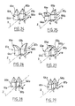
- the teeth 61a and 61b can have various configurations, illustrated very schematically by Figures 24 to 29, in which two teeth have been shown consecutive 61a and 61b having respective bases 64a and 64h and upper parts respective 65a and 65b extending from the bases.
- the upper parts 65a and 65b and in in particular the free ends are of the same axis as the bases 64a and 64b respectively.
- the free ends are substantially parallel.
- the upper parts 65a and 65b and in in particular the free ends are inclined forward and back respectively.
- the free ends of the teeth are inclined towards ends opposite of the base.
- the upper parts 65a and 65b are inclined respectively to the left and to the right, when the application element is viewed from the front.
- the upper parts 65a and 65b are tilted respectively to the right and to the left and can cross when the application element is viewed from the front.
- the upper parts can keep towards each other without cross.
- the upper parts of the teeth are, in more to be tilted respectively to the left and to the right, tilted forward and backward respectively, or vice versa.
- the bases of the teeth 64a and 64b are overlap along the Z axis when the application element is viewed from the side, in a direction perpendicular to the Z axis.
- the bases 64a and 64b of the teeth are overlap with faces extending substantially along an axis perpendicular to the Z axis, when the application element is viewed from the front.
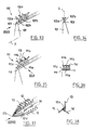
- FIGS. 30 to 32 show a row 70 of elements, this row 70 comprising a first series of teeth 70a and a second series of teeth 70b, these teeth being made in one piece with a base 72 and being respectively located alternately on either side of a geometric separation surface S, as we can see it in figure 32.
- the envelope (i.e. the peripheral outer surface) of row 70 of teeth is a substantially triangular director cylinder, as can be seen on the figure 32.
- the depth b of the teeth 70a and 70b at their connection to the base 72 is greater than their width e and also greater than the interval c between two consecutive teeth 70a or 70b.
- the ratio of the interval separating two adjacent teeth from the same side of the geometric separation surface at the width of the tooth arranged on the side opposite of the geometric separation surface, between the two adjacent teeth is included between 0.2 and 2 approximately, the above-mentioned interval and width being preferably measured substantially halfway up the teeth.
- teeth 70a and 70b are capable of resist a stress exerted transversely to the Z axis of the base, which allows separate the eyelashes and smooth the product deposited on their surface, even if the product used would have partially hardened.
- Each tooth 70a or 70b has a lower part 74 having faces front 75 and rear 76 substantially flat and parallel, perpendicular to the Z axis, and a upper part 77 having front 7X and rear 79 faces converging towards the top of the tooth, so that the upper part 77 of each tooth has a general shape tapered when the application element is viewed from the side as in Figure 31.
- the lower parts 74 of three consecutive teeth of row 70 form between them and with the base 72 a cavity 80 intended to contain product for the purpose of place on the eyelashes.
- the lower parts 74 of two consecutive teeth are substantially contiguous, as shown in Figure 31.
- the upper parts 77 of these same teeth form between them, when the application element is observed from the side as in FIG. 31, forks allowing to grip the eyelashes, to separate them, to comb them and to smooth the deposited product their surface.
- the upper parts 77 of the teeth form between them, when the application element is viewed from the side, notches in the form of notches 82, the bottom 83 of which is located at a certain distance d from the base 72, this distance d being preferably greater than or equal to 0.2 mm.
- the distance d is of the order of 2 mm.
- the total height of the teeth being of the order of 3 mm.
- the spacing between the teeth of the same series of teeth that is to say the teeth 70a or 70b, can be relatively large in favor of the quantity of product which loads the application element without the application element losing its ability to grip the eyelashes, thanks to the offset teeth and the fact that the notches 82 formed by the upper parts 77 of the teeth remain sufficiently narrow.
- FIG. 33 shows a row 100 of teeth produced from a single holding by plastic molding with a base 101, of axis Z.
- Row 100 has two sets of teeth 102a and 102b arranged in alternation, whose bases 103 are aligned parallel to the Z axis of the base 101 and whose the upper parts are offset respectively on either side of a surface separation geometry S, constituted here by a plane extending parallel to the hases 103 of the teeth.
- the height of the bases 103 of the teeth is of the order of one or a few millimeters in the example described, preferably being greater than or equal to 0.2 mm.
- Two successive teeth form notches between them allowing the application element to grip the eyelashes, while the offset upper parts of the teeth form cavities between them to build up product reserves on the application element.
- FIGS. 35 and 36 show a row of teeth 110 comprising a first series of teeth 111a and a second series of teeth 111b.
- the bases 112 of all the teeth are aligned, the bases of the teeth 111a alternating with the bases of the teeth 111b.
- the upper parts 113 of the teeth 111a are oriented to the right and towards the rear, while the upper parts of the teeth 111b are oriented to the left and forward, so that the upper parts 113 of teeth 111a and 111b intersect when the application element is viewed from the side, as in Figure 36.
- the upper ends 114 of the intersecting teeth define therebetween grooves for gripping the eyelashes, while the bases of the teeth define between they cavities for accommodating product reserves.
- the applicator element has a distal end having a generally tapered shape to facilitate its retraction in the container.
- FIGS. 37 and 38 show the front part of a application element which differs from that shown in FIGS. 1 to 5 by the fact that the base 12 is extended at the front by a part 12a of generally tapered shape. the rows 13, 14 and 15 of elements extending along the edges of this tapered portion 12a to the front point 12b, while having a height which decreases up to said point.
- the rows of elements 13, 14 and 15 are not not extend on the front tapered part.
- Figure 39 shows an application system in which the product is contained in a container 390 in the form of a tube.
- This tube is preferably made of a flexible material which allows compress the tube and distribute the product on the application element 391 of the applicator.
- distributors can also be used to distribute the product on the application element, for example distributors of the pump type and are considered to fall within the scope of the invention.
- the application system shown in Figure 40 includes a container 400 containing a solid loaf of product 410.
- the application element 401 is moved through product 410.
- This product bar can be moistened and the element 401 application moved through the humidified part of the product to load the element of application.
- the application element can be moistened and moved over product not humidified.
- the rod itself can serve as a handle.
- Figure 41 shows another embodiment.
- the applicator shown in this figure has a tip 415 extending to from the distal end of the applicator element 411.
- Tip 415 can load with product when the application element is loaded with product and can be used to draw the eye area or to be inserted between isolated lashes.
- Figures 42 and 43 show applicators having elements 421, 431 with bases 422, 433 of substantially cross section triangular.
- the base 423 shown in FIG. 42 has non-planar sides which are concave, while the base 433 shown in Figure 43 has planar sides.
- Each application element 421, 431 has three projecting elements having in the form of rows of consecutive individual elements 425a-425c, and 435a-435c.
- the consecutive individual elements of each row have parts substantially contiguous at their corners.
- each row also have parts free ends arranged alternately on either side of a geometric surface of separation.
- FIG. 44 represents an applicator having an application element 441 with a base 443 similar, in general, to the base 433 of the application element 431 of figure 43.
- the projecting elements connecting to the base 443 include each a row of consecutive individual elements which do not have parts arranged alternately on either side of a geometric separation surface.
- each row 445a-445c are substantially aligned along the length of the base 443.
- the applicator element 441 may also include a plurality of rows bristles 446a-446c, each row being arranged on one side of the base 443 between adjacent rows of individual elements, the rows of bristles extending substantially radially from the corresponding sides of the base.
- Figures 45-50 each show an application element having a base of polygonal cross section with a plurality of projecting elements extending substantially in the continuation of different sides of the base.
- Adjacent projecting elements extend to from the base in substantially different directions and are oriented substantially in the same roundabout direction around a longitudinal axis of the base.
- the projecting elements have a free serrated edge to provide an effect eyelash grip when they are brought into contact.
- the applicator element of FIG. 45 comprises a base 453 having a substantially constant cross section of square shape and four projecting elements 455a-455d extending from the base.
- a plurality of reliefs 457 is arranged so as to extend from one side of the base 453 along an individual element adjacent to this side but without be located in the extension of this side.
- the application element shown in Figure 46 has a base 463 of non-constant triangular section with three projecting elements 465a-465c extending to from the base.
- the projecting elements have a free edge which is substantially concave towards the outside, the curvature of which is preferably adapted to the curvature of the eyelid.
- FIG. 47 represents an application element with a base 473 of non-constant triangular section, with three projecting elements extending in the continuation of the respective sides of the base.
- the projecting elements 475a-475c have each a free edge substantially convex towards the outside.
- FIG. 48 represents an application element with a base 483 having a constant cross section of square shape.
- Four projecting elements 485a-485b are arranged substantially in continuation of each of the corresponding sides of base 483.
- the projecting elements of FIG. 48 each have a height varying along the base 483.
- FIG. 49 represents an application element with a base 493 having a non-constant square cross section.
- Base 493 has a cross section increasing from the end proximal of the applicator member toward its distal end.
- Four projecting elements 495a-495d are arranged on the base substantially in continuation of the corresponding sides of the base 493.
- FIG. 50 represents an application element having a base 503 of constant cross section, octagonal, with four projecting elements 505a-505d extending respectively from pairs of opposite sides of their base 503.
- Projecting elements extending from the base from pairs of opposite sides are oriented in opposite directions.
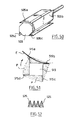
- Figure 51 illustrates how an applicator according to the invention can contain product P in substantially open volumes formed between each element projecting 515a-515d and the adjacent side of the base other than the side whose element projection extends substantially in the extension.
- the product height on the applicator is preferably substantially equal to the height of the protruding element which does not extend in the extension of the side on which the volume of product considered is deposited (i.e. the projecting element 515a in FIG. 51, for example).
- the height of the product preferably decreases from the protruding element where the quantity of product is greatest, along the side concerned, up to the element in projection extending in the extension of this side (i.e. element 515b on the figure 51 for example).
- This configuration allows the eyelashes E to come into contact with the contained product. in an open volume and load with the product when the side defining a part of this volume is moved substantially parallel to the eyelashes.
- the eyelash can come into contact with a corresponding projecting element, for example the projecting element 515a shown in FIG. 51, which can then smooth the product along the lash and also lengthen and curl it.
- the projecting element will have parts capable of gripping the eyelash, as described above.
- providing a plurality of elements projecting allows to constitute a plurality of corresponding volumes containing the product and the application steps described above can be repeated several time. This allows the product to be applied without having to reload the application element frequently.
- both the height of the projecting elements and depth of the teeth or slots of the free edge can be changed to achieve different effects.
- the quantity of product that is deposited between the element projection and the adjacent side of the base can be increased or decreased
- Figure 52 shows a protruding element in the form of a row of consecutive individual elements 525 covered with a flocking.
- Projecting elements or rows of individual elements can also have hollow parts with an opening on one side of the element, giving access to the hollow portion. These hollow portions can be filled with product thus allowing the applicator to contain an even greater quantity of product to be apply on the eyelashes.
- the application element may have a surface which makes it possible to increase the quantity of product with which the application element is loaded.
- a projecting element, or even a row of individual elements and / or the base may have capillary grooves or flocking, on all or part of their surface.
- FIG. 52 An example of flocking on teeth is shown in FIG. 52.
- the projecting elements or the individual elements may have a height which varies according to the axial positioning on the application element, by example an increasing, decreasing, decreasing then increasing or increasing height then decreasing, from front to back.
- Protruding elements can undergo a surface treatment by abrasion, for example to form forks at the end of the teeth or hair.
- Projecting elements or individual elements can be treated hot to round off their tip, for example, or even form a ball at their end free. Protruding elements or individual elements thus become less aggressive vis-à-vis the eyelashes.
- All or part of the application element can be covered with a coating such as a varnish for example, intended to impart better sliding on the eyelashes or otherwise more roughness.
- a slip-enhancing material may also alternatively be, or additionally, added to the material used to make the application element.
- the application element and in particular the projecting elements, can also include active ingredients such as preservatives, moisture absorbers, salts metallic, including copper, magnetic particles and other similar materials appropriate, intended to be released into the product when it is loaded on the element of application.
- active ingredients such as preservatives, moisture absorbers, salts metallic, including copper, magnetic particles and other similar materials appropriate, intended to be released into the product when it is loaded on the element of application.
- assets can either be included in the material used to make the application element, or be deposited in the form of a coating on the element application, or both.
- products can be used to modify the surface tension of the application element in contact with moisture.
- the device according to the invention is preferably produced by injecting material plastic, but as a variant it is possible to use processes for conformation of material by compression, stamping or bar turning.
- the base may include notches or reliefs arranged to contain product.
- the projecting elements can be made of a material different from that used to make the base or part of the application element on which they are willing.
- the length of a row of consecutive individual elements is between 10 and 45 mm approximately, preferably 15 and 28 mm approximately and preferably another 20 and 26 mm approximately.
- the height of the projecting elements is preferably between 0.5 and 15 mm approximately and more preferably between 7 and 13 mm approximately.
- the number of individual elements per row is preferably between 6 and approximately 50 mm, preferably between approximately 10 and 35 mm, and more preferably between 15 and 32 approximately.
Landscapes
- Brushes (AREA)
- Coating Apparatus (AREA)
- Closures For Containers (AREA)
- Cosmetics (AREA)
- Containers And Packaging Bodies Having A Special Means To Remove Contents (AREA)
Applications Claiming Priority (2)
| Application Number | Priority Date | Filing Date | Title |
|---|---|---|---|
| FR9909453 | 1999-07-21 | ||
| FR9909453A FR2796530B1 (fr) | 1999-07-21 | 1999-07-21 | Dispositif pour le peignage des cils ou des sourcils et dispositif de conditionnement et d'application ainsi equipe |
Publications (2)
| Publication Number | Publication Date |
|---|---|
| EP1070468A1 true EP1070468A1 (de) | 2001-01-24 |
| EP1070468B1 EP1070468B1 (de) | 2008-02-13 |
Family
ID=9548346
Family Applications (1)
| Application Number | Title | Priority Date | Filing Date |
|---|---|---|---|
| EP00402092A Expired - Lifetime EP1070468B1 (de) | 1999-07-21 | 2000-07-21 | Vorrichtung zum Auftragen eines Mittels auf Wimpern oder Augenbrauen |
Country Status (12)
| Country | Link |
|---|---|
| US (1) | US6343607B1 (de) |
| EP (1) | EP1070468B1 (de) |
| JP (1) | JP3583696B2 (de) |
| CN (1) | CN1310606C (de) |
| AR (1) | AR024894A1 (de) |
| AT (1) | ATE385717T1 (de) |
| BR (1) | BR0003071B1 (de) |
| CA (1) | CA2314318C (de) |
| DE (1) | DE60037987T2 (de) |
| ES (1) | ES2300248T3 (de) |
| FR (1) | FR2796530B1 (de) |
| MX (1) | MXPA00007118A (de) |
Cited By (15)
| Publication number | Priority date | Publication date | Assignee | Title |
|---|---|---|---|---|
| WO2002056726A3 (de) * | 2001-01-19 | 2002-09-19 | Beiersdorf Ag | Applikator für flüssige oder pastöse medien, insbesondere dekorative kosmetika wie mascara |
| FR2831033A1 (fr) | 2001-10-23 | 2003-04-25 | Oreal | Dispositif pour le conditionnement et/ou l'application d'un produit sur les cils et/ou les sourcils et procede de maquillage |
| EP1342428A1 (de) | 2002-03-05 | 2003-09-10 | L'oreal | Vorrichtung zum Kämmen und/oder Bürsten von Wimpern und/oder Augenbrauen und/oder zum Auftragen auf diese |
| FR2837077A1 (fr) | 2002-03-13 | 2003-09-19 | Oreal | Dispositif pour peigner les cils et/ou les sourcils et/ou appliquer un produit sur ceux-ci |
| EP1561394A3 (de) * | 2004-02-06 | 2005-10-12 | L'oreal | Vorrichtung zum Aufbewahren und Auftragen eines Produktes mit einem Abstreifelement |
| EP2016864A1 (de) | 2004-10-21 | 2009-01-21 | L'Oreal | Vorrichtung zum Verpacken und Auftragen eines Produkts auf die Wimpern oder die Augenbrauen, insbesondere für Wimperntusche |
| FR2930875A1 (fr) * | 2008-04-18 | 2009-11-13 | Ile M V R Soc Civ Soc Civ | Dispositif applicateur d'un produit cosmetique fluide ou pateux, typiquement du mascara |
| WO2010067314A1 (en) | 2008-12-11 | 2010-06-17 | L'oreal | An applicator for applying a cosmetic, makeup, or care product composition to keratinous materials |
| FR2955018A1 (fr) * | 2010-01-11 | 2011-07-15 | Oreal | Applicateur cosmetique. |
| USD749327S1 (en) | 2013-11-12 | 2016-02-16 | Geka Gmbh | Cosmetic brush |
| EP3545790A1 (de) * | 2007-02-21 | 2019-10-02 | Chanel Parfums Beauté | Applikator und behälter mit diesem applikator und applikatorcharge |
| WO2020127830A1 (en) | 2018-12-19 | 2020-06-25 | L'oreal | Applicator for applying a cosmetic product to the eyelashes and/or eyebrows |
| WO2020127845A1 (en) | 2018-12-19 | 2020-06-25 | L'oreal | Application device for applying a cosmetic product to the eyelashes and/or eyebrows |
| EP3685982A1 (de) | 2019-01-28 | 2020-07-29 | Texen Services | Aufbringung eines produkts auf einen oberflächenteil des menschlichen körpers |
| US11523672B2 (en) | 2019-04-14 | 2022-12-13 | Toly Management Ltd. | Cosmetic applicator with flexible fluid retaining portion |
Families Citing this family (61)
| Publication number | Priority date | Publication date | Assignee | Title |
|---|---|---|---|---|
| WO2001005271A1 (fr) * | 1999-07-21 | 2001-01-25 | L'oreal | Dispositif pour l'application d'un produit sur les fibres keratiniques |
| FR2805720B1 (fr) * | 2000-03-03 | 2002-08-16 | Oreal | Dispositif comprenant un applicateur et/ou un organe d'essorage magnetique |
| FR2809295B1 (fr) | 2000-05-26 | 2002-08-09 | Oreal | Dispositif pour l'application d'un produit, cosmetique ou de soin, sur les fibres keratiniques, notamment les cils ou les sourcils |
| BR0106967B1 (pt) | 2000-07-12 | 2009-05-05 | dispositivo de acondicionamento e/ou de aplicação de um produto cosmético e/ou de cuidados a ser aplicado à pele, cabelo ou unhas e processo de fabricação do dispositivo. | |
| US20020124865A1 (en) * | 2001-03-08 | 2002-09-12 | Davis Susan K. | Eyelash makeup shield with grooves |
| USD536129S1 (en) | 2002-03-08 | 2007-01-30 | Davis Susan K | Eyelash makeup shield with grooves |
| US20030221273A1 (en) * | 2002-05-28 | 2003-12-04 | Phillip Mark | Method and apparatus for injection molding a plastic monolith |
| US8210186B2 (en) * | 2002-11-27 | 2012-07-03 | L'oreal | Applicator for applying a substance onto keratinous fibers |
| FR2850549B1 (fr) * | 2003-02-04 | 2006-07-14 | Oreal | Brosse pour l'application d'un produit sur les cils ou les sourcils |
| FR2855379B1 (fr) | 2003-05-27 | 2005-07-29 | Oreal | Dispositif de conditionnement et d'application |
| FR2870697B1 (fr) | 2004-05-25 | 2006-08-11 | Oreal | Dispositif de conditionnement et d'application d'un produit |
| FR2872394B1 (fr) * | 2004-07-01 | 2007-04-20 | Oreal | Dispositif pour l'application d'un produit sur les fibres keratiniques |
| FR2874798B1 (fr) | 2004-09-03 | 2007-01-19 | Oreal | Applicateur pour l'application d'un produit sur les cils ou les sourcils |
| US8127777B2 (en) * | 2004-09-03 | 2012-03-06 | L'oreal S.A. | Applicator for applying a substance |
| FR2882506B1 (fr) | 2005-02-25 | 2007-05-18 | Oreal | Procede de maquillage au moyen d'un applicateur vibrant |
| US20060225760A1 (en) * | 2005-04-06 | 2006-10-12 | Crown Packaging Technology, Inc., United States | Flocked wire mascara brush |
| FR2884501B1 (fr) * | 2005-04-19 | 2007-06-08 | Oreal | Dispositif de conditionnement et d'application d'un produit, par exemple cosmetique |
| US20060260633A1 (en) | 2005-05-19 | 2006-11-23 | Wyatt Peter J | Cosmetic composition system with thickening benefits |
| DE502005006820D1 (de) * | 2005-08-11 | 2009-04-23 | Geka Brush Gmbh | Bürstchen zum Auftragen kosmetischer Massen |
| FR2891708B1 (fr) * | 2005-10-10 | 2010-12-17 | Oreal | Dispositif de conditionnement et d'application d'un produit. |
| US20080115798A1 (en) * | 2006-06-08 | 2008-05-22 | Donald Frank Rainey | Ultra-size cosmetic applicator having enhanced surface area |
| FR2902984B1 (fr) * | 2006-06-28 | 2009-03-20 | Oreal | Dispositif pour l'application d'un produit sur les cils ou les sourcils. |
| US8096306B2 (en) * | 2006-07-12 | 2012-01-17 | Albea Services | Molded plastic mascara brush |
| US20080178901A1 (en) * | 2007-01-26 | 2008-07-31 | Antonio Montoli | Molded mascara brush with oval core |
| KR100820075B1 (ko) | 2007-01-26 | 2008-04-07 | (주)씨피아이케이알 | 마스카라 브러시 |
| FR2913319B1 (fr) * | 2007-03-05 | 2011-02-11 | Lvmh Rech | Dispositif applicateur de produit cosmetique et utilisation d'un tel dispositif. |
| FR2917585B1 (fr) | 2007-06-22 | 2010-10-15 | Oreal | Applicateur pour appliquer un produit sur les cils et/ou les sourcils. |
| US8042555B2 (en) * | 2007-09-05 | 2011-10-25 | Elc Management Llc | Head for a cosmetic applicator |
| FR2922422B1 (fr) * | 2007-10-23 | 2009-12-18 | Oreal | Applicateur pour peigner ou appliquer un produit sur les cils |
| FR2922421B1 (fr) | 2007-10-23 | 2010-01-29 | Oreal | Applicateur pour peigner ou appliquer un produit sur les cils ou les sourcils |
| FR2922420B1 (fr) * | 2007-10-23 | 2011-04-01 | Oreal | Applicateur pour l'application d'un produit sur les cils ou les sourcils |
| FR2983689A1 (fr) * | 2007-10-23 | 2013-06-14 | Oreal | Applicateur pour peigner ou appliquer un produit sur les cils et/ou les sourcils |
| FR2931643B1 (fr) * | 2008-06-03 | 2011-10-14 | Dior Christian Parfums | Composant de brosse a mascara, brosse a mascara et ensemble d'application de mascara |
| FR2932070B1 (fr) | 2008-06-10 | 2012-08-17 | Oreal | Ensemble de maquillage et/ou de soin des cils |
| FR2933854B1 (fr) * | 2008-07-16 | 2011-08-26 | Oreal | Applicateur pour peigner ou appliquer un produit sur les cils ou les sourcils. |
| FR2936691B1 (fr) * | 2008-10-06 | 2012-12-07 | Oreal | Instrument pour appliquer un produit sur des phaneres et procede de fabrication afferent |
| FR2938758A1 (fr) * | 2008-11-24 | 2010-05-28 | Oreal | Procede de maquillage ou de soin des cils ou des sourcils utilisant un polymere supramoleculaire a base de polyalcene |
| FR2939619B1 (fr) * | 2008-12-15 | 2011-02-11 | Oreal | Applicateur pour appliquer un produit sur les matieres keratiniques. |
| FR2943253B1 (fr) | 2009-03-20 | 2011-04-22 | Oreal | Composition contenant l'association de madecassoside, d'une arginine et de polysorbate |
| FR2943227B1 (fr) * | 2009-03-20 | 2011-06-03 | Oreal | Applicateur pour appliquer un produit cosmetique sur les cils ou les sourcils |
| USD616608S1 (en) | 2009-10-26 | 2010-05-25 | Mary Kay Inc. | Mascara container |
| FR2954060B1 (fr) * | 2009-12-22 | 2012-03-02 | Oreal | Brosse pour l'application d'un produit sur les cils et/ou les sourcils. |
| US8568049B2 (en) * | 2010-03-16 | 2013-10-29 | Geka Gmbh | Mascara brush with eyelash retaining member |
| FR2962888B1 (fr) | 2010-07-20 | 2012-08-31 | Oreal | Applicateur et dispositif de conditionnement et d'application comportant un tel applicateur. |
| DE202010017159U1 (de) * | 2010-12-30 | 2012-04-03 | Geka Gmbh | Applikatoreinrichtung, insbesondere für einen Mascaraapplikator, Kosmetikapplikator, insbesondere Mascaraapplikator aufweisend die Applikatoreinrichtung und Applikationseinheit aufweisend die Applikatoreinrichtung |
| DE202010017160U1 (de) * | 2010-12-30 | 2012-04-03 | Geka Gmbh | Applikatoreinrichtung, insbesondere für einen Kosmetikapplikator, Applikator, insbesondere Kosmetikapplikator aufweisend die Applikatoreinrichtung sowie Applikationseinheit, insbesondere Kosmetikeinheit aufweisend die Applikatoreinrichtung |
| FR2976165B1 (fr) | 2011-06-07 | 2014-10-24 | Oreal | Ensemble comportant une composition contenant des fibres pour le maquillage des cils. |
| US9526316B2 (en) * | 2013-05-21 | 2016-12-27 | Zen Design Solutions Limited | Cosmetic applicator |
| FR3007259B1 (fr) | 2013-06-19 | 2015-09-18 | Oreal | Applicateur pour appliquer un produit sur les cils ou sourcils |
| EP3010368B1 (de) * | 2013-06-20 | 2018-05-02 | L'oreal | Applikator zum auftragen eines produkts auf die wimpern, die augenbrauen oder die haut |
| FR3028152B1 (fr) * | 2014-11-07 | 2018-01-12 | L'oreal | Applicateur d'un produit cosmetique, de maquillage ou de soin, sur les cils et/ou les sourcils |
| FR3032869B1 (fr) | 2015-02-25 | 2018-05-11 | Societe Industrielle De Matieres Plastiques | Dispositif applicateur d'un produit de type fluide ou pateux sur des fibres keratiniques. |
| FR3043531B1 (fr) * | 2015-11-17 | 2019-05-24 | L'oreal | Applicateur pour l'application d'un produit cosmetique |
| KR200486386Y1 (ko) * | 2016-06-24 | 2018-05-10 | 주식회사 엘지생활건강 | 마스카라 |
| FR3070841B1 (fr) * | 2017-09-12 | 2021-07-16 | Oreal | Applicateur cosmetique |
| FR3070842B1 (fr) | 2017-09-12 | 2021-07-16 | Oreal | Applicateur cosmetique |
| FR3070839B1 (fr) * | 2017-09-12 | 2025-04-11 | Oreal | Applicateur cosmetique |
| FR3098697B1 (fr) | 2019-07-16 | 2022-07-15 | Oreal | Essoreur d’applicateur de produit cosmétique, dispositif et procédé d’application associés |
| FR3104012B1 (fr) * | 2019-12-09 | 2024-07-12 | Oreal | Brosse pour l’application d’une composition sur les cils ou sourcils |
| EP4728927A2 (de) | 2021-03-31 | 2026-04-22 | GEKA GmbH | Applikator mit mikroelementen und verfahren zur herstellung eines applikators mit mikroelementen |
| JP2024524293A (ja) * | 2021-06-29 | 2024-07-05 | ソシエテ アンデュストリエル ドゥ マティエール プラスティック | 流体状またはペースト状の製品をケラチン繊維に塗布するためのアプリケータ装置 |
Citations (7)
| Publication number | Priority date | Publication date | Assignee | Title |
|---|---|---|---|---|
| US3669130A (en) * | 1971-06-16 | 1972-06-13 | Frank G Petroczky | Hair combs |
| US3921650A (en) * | 1974-12-23 | 1975-11-25 | Max Factor & Co | Cosmetic applicator and container |
| DE2559273A1 (de) * | 1975-12-31 | 1977-07-07 | Werner Blankschein | Rundbuerste, insbesondere augenwimpernbuerste, aus kunststoff und verfahren zu deren herstellung |
| US4403624A (en) * | 1981-09-25 | 1983-09-13 | Montgomery Robin M | Cosmetic applicator and container system |
| GB2146520A (en) * | 1983-09-19 | 1985-04-24 | Bridgeport Metal Goods Mfg Co | Contoured flocked cosmetics brush flexers |
| WO1995017837A1 (en) * | 1993-12-30 | 1995-07-06 | The Procter & Gamble Company | Cosmetic applicator brush having variable bristle density |
| WO1997028719A1 (fr) * | 1996-02-12 | 1997-08-14 | Lvmh Recherche | Brosse perfectionnee pour le maquillage des cils de l'oeil |
Family Cites Families (50)
| Publication number | Priority date | Publication date | Assignee | Title |
|---|---|---|---|---|
| US466496A (en) | 1892-01-05 | Isaac w | ||
| US155977A (en) | 1874-10-13 | Improvement in curry-combs | ||
| US791690A (en) | 1903-12-29 | 1905-06-06 | American Hard Rubber Co | Comb. |
| US1094013A (en) | 1910-03-21 | 1914-04-21 | Charles Peterson | Toilet or hair comb. |
| US1580365A (en) | 1924-05-24 | 1926-04-13 | William S Bechtold | Comb |
| US1670161A (en) | 1927-09-07 | 1928-05-15 | Lena M Meyer | Self-cleaning comb |
| US1780206A (en) | 1929-01-30 | 1930-11-04 | Archibald D Mckellar | Comb |
| US1963389A (en) | 1931-05-08 | 1934-06-19 | Vardeman Lab Inc Dr | Toothbrush |
| US1829228A (en) | 1931-05-15 | 1931-10-27 | Lewis Charles | Comb |
| US1892749A (en) | 1932-05-10 | 1933-01-03 | Philaja Nels | Comb |
| US2007245A (en) * | 1934-06-22 | 1935-07-09 | Gimonet Alexandre | Cosmetic device |
| US1989185A (en) | 1934-09-29 | 1935-01-29 | Clein Elias | Comb |
| US2175344A (en) | 1939-02-18 | 1939-10-10 | Friedman Joseph | Massage comb |
| US2264346A (en) | 1940-08-06 | 1941-12-02 | Earl S Tupper | Comb |
| US2255618A (en) | 1940-12-26 | 1941-09-09 | Delamere Co Inc | Hair device |
| US2348339A (en) | 1943-09-22 | 1944-05-09 | Golden Samuel | Comb |
| US2596296A (en) | 1948-12-16 | 1952-05-13 | Lavelle W Shields | Comb |
| US2569246A (en) | 1949-03-02 | 1951-09-25 | Ada C Marcellus | Combined eyelash curler, mascara applicator, and remover |
| FR1000173A (fr) | 1949-11-08 | 1952-02-08 | Peigne | |
| US2626618A (en) | 1950-06-16 | 1953-01-27 | Curtis L Collison | Comb |
| US2655925A (en) | 1952-05-08 | 1953-10-20 | Du Pont | Comb |
| FR1068192A (fr) | 1952-12-05 | 1954-06-23 | Perfectionnements aux peignes | |
| US3033213A (en) * | 1958-05-26 | 1962-05-08 | Rubinstein Inc H | Mascara applicator |
| US3312583A (en) | 1963-10-02 | 1967-04-04 | James J Rochlis | Apertured and staggered molded pile product |
| FR1531835A (fr) | 1967-07-11 | 1968-07-05 | Wiener Kammfabrik Anton Abraha | Améliorations et perfectionnements apportés à un peigne à coiffer |
| US3763870A (en) | 1971-08-02 | 1973-10-09 | Max Factor & Co | Apparatus and method for applying cosmetics |
| US3862639A (en) | 1973-03-28 | 1975-01-28 | Revlon | Mascara applicator |
| US3892248A (en) | 1974-03-15 | 1975-07-01 | Plough | Eyelash-cosmetic applicator |
| US3930280A (en) | 1974-06-27 | 1976-01-06 | The Bridgeport Metal Goods Manufacturing Company | Bottle insert for product container |
| DE3171667D1 (en) | 1980-04-19 | 1985-09-12 | Geka Brush Georg Karl Gmbh | Mascara brush and method for its production |
| FR2505633B1 (fr) | 1981-05-18 | 1985-09-06 | Oreal | Brosse a cils perfectionnee, procede pour sa fabrication et dispositif pour la mise en oeuvre de ce procede |
| US4712936A (en) | 1981-06-26 | 1987-12-15 | Milton Kessler | One-piece cap and brush and method of forming it |
| US4422986A (en) | 1981-09-23 | 1983-12-27 | Cole William E | Method and apparatus for infection molding brushes |
| US4744377A (en) | 1982-07-07 | 1988-05-17 | Avon Products, Inc. | Mascara applicator |
| US4804004A (en) | 1983-03-18 | 1989-02-14 | Taylor Charles H | Molded mascara applicator |
| US4565205A (en) | 1983-03-18 | 1986-01-21 | Super Brush Co., Inc. | Molded mascara applicator |
| US4660582A (en) | 1983-03-18 | 1987-04-28 | Super Brush Co., Inc. | Molded mascara application |
| US4635659A (en) | 1984-01-05 | 1987-01-13 | Spatz Laboratories, Inc. | Mascara applicator |
| GB2159699B (en) | 1984-05-23 | 1988-06-02 | Rodney David Cole | An applicator for the application of cosmetic products |
| US5007442A (en) | 1988-01-11 | 1991-04-16 | Hirzel Suzy C | Double blocking members sealing a single opening means |
| US5046213A (en) | 1990-03-29 | 1991-09-10 | Colgate-Palmolive Company | Plaque removing toothbrush |
| EP0474934A1 (de) | 1990-09-14 | 1992-03-18 | Aceworld Plastics Co Ltd | Anordnung für Bürstenborsten |
| US5086793A (en) | 1990-11-13 | 1992-02-11 | Maybe Holding Co. | Adjustable mascara applicator |
| US5137387A (en) | 1991-06-11 | 1992-08-11 | Maybe Holding Co., Inc. | Cosmetic applicator with rotary wiping system |
| JPH07322915A (ja) | 1994-06-01 | 1995-12-12 | Shiseido Co Ltd | 化粧用櫛 |
| FR2738127B1 (fr) * | 1995-08-30 | 1998-03-27 | Oreal | Applicateur de mascara |
| JPH09108033A (ja) | 1995-10-23 | 1997-04-28 | Shiseido Co Ltd | コーム及びコームの製造法 |
| FR2748636B1 (fr) | 1996-05-15 | 1998-07-10 | Lvmh Rech | Brosse perfectionnee pour l'application d'un produit liquide pateux ou poudreux tel que notamment du mascara |
| FR2748913B1 (fr) | 1996-05-24 | 1998-08-07 | Oreal | Brosse a crans et dispositif de maquillage comprenant cette brosse |
| US5951185A (en) | 1997-01-28 | 1999-09-14 | Henlopen Manufacturing Co., Inc. | Fluid material dispenser |
-
1999
- 1999-07-21 FR FR9909453A patent/FR2796530B1/fr not_active Expired - Fee Related
-
2000
- 2000-07-20 MX MXPA00007118A patent/MXPA00007118A/es active IP Right Grant
- 2000-07-21 EP EP00402092A patent/EP1070468B1/de not_active Expired - Lifetime
- 2000-07-21 DE DE60037987T patent/DE60037987T2/de not_active Expired - Lifetime
- 2000-07-21 BR BRPI0003071-6A patent/BR0003071B1/pt not_active IP Right Cessation
- 2000-07-21 JP JP2000254625A patent/JP3583696B2/ja not_active Expired - Lifetime
- 2000-07-21 ES ES00402092T patent/ES2300248T3/es not_active Expired - Lifetime
- 2000-07-21 CN CNB00122204XA patent/CN1310606C/zh not_active Expired - Lifetime
- 2000-07-21 CA CA002314318A patent/CA2314318C/fr not_active Expired - Lifetime
- 2000-07-21 US US09/624,004 patent/US6343607B1/en not_active Expired - Lifetime
- 2000-07-21 AR ARP000103758A patent/AR024894A1/es unknown
- 2000-07-21 AT AT00402092T patent/ATE385717T1/de not_active IP Right Cessation
Patent Citations (7)
| Publication number | Priority date | Publication date | Assignee | Title |
|---|---|---|---|---|
| US3669130A (en) * | 1971-06-16 | 1972-06-13 | Frank G Petroczky | Hair combs |
| US3921650A (en) * | 1974-12-23 | 1975-11-25 | Max Factor & Co | Cosmetic applicator and container |
| DE2559273A1 (de) * | 1975-12-31 | 1977-07-07 | Werner Blankschein | Rundbuerste, insbesondere augenwimpernbuerste, aus kunststoff und verfahren zu deren herstellung |
| US4403624A (en) * | 1981-09-25 | 1983-09-13 | Montgomery Robin M | Cosmetic applicator and container system |
| GB2146520A (en) * | 1983-09-19 | 1985-04-24 | Bridgeport Metal Goods Mfg Co | Contoured flocked cosmetics brush flexers |
| WO1995017837A1 (en) * | 1993-12-30 | 1995-07-06 | The Procter & Gamble Company | Cosmetic applicator brush having variable bristle density |
| WO1997028719A1 (fr) * | 1996-02-12 | 1997-08-14 | Lvmh Recherche | Brosse perfectionnee pour le maquillage des cils de l'oeil |
Cited By (24)
| Publication number | Priority date | Publication date | Assignee | Title |
|---|---|---|---|---|
| WO2002056726A3 (de) * | 2001-01-19 | 2002-09-19 | Beiersdorf Ag | Applikator für flüssige oder pastöse medien, insbesondere dekorative kosmetika wie mascara |
| US7325550B2 (en) | 2001-01-19 | 2008-02-05 | Beiersdorf Ag | Applicator for liquid or paste-like media, in particular decorative cosmetics such as mascara |
| FR2831033A1 (fr) | 2001-10-23 | 2003-04-25 | Oreal | Dispositif pour le conditionnement et/ou l'application d'un produit sur les cils et/ou les sourcils et procede de maquillage |
| US7121284B2 (en) | 2001-10-23 | 2006-10-17 | L'oreal S.A. | Product applicator for eyelashes and/or eyebrows, and method of product application |
| EP1342428A1 (de) | 2002-03-05 | 2003-09-10 | L'oreal | Vorrichtung zum Kämmen und/oder Bürsten von Wimpern und/oder Augenbrauen und/oder zum Auftragen auf diese |
| FR2837077A1 (fr) | 2002-03-13 | 2003-09-19 | Oreal | Dispositif pour peigner les cils et/ou les sourcils et/ou appliquer un produit sur ceux-ci |
| EP1561394A3 (de) * | 2004-02-06 | 2005-10-12 | L'oreal | Vorrichtung zum Aufbewahren und Auftragen eines Produktes mit einem Abstreifelement |
| US7476044B2 (en) | 2004-02-06 | 2009-01-13 | L'oreal | Packaging and applicator device including a wiper member |
| EP2016864A1 (de) | 2004-10-21 | 2009-01-21 | L'Oreal | Vorrichtung zum Verpacken und Auftragen eines Produkts auf die Wimpern oder die Augenbrauen, insbesondere für Wimperntusche |
| EP3545790A1 (de) * | 2007-02-21 | 2019-10-02 | Chanel Parfums Beauté | Applikator und behälter mit diesem applikator und applikatorcharge |
| FR2930875A1 (fr) * | 2008-04-18 | 2009-11-13 | Ile M V R Soc Civ Soc Civ | Dispositif applicateur d'un produit cosmetique fluide ou pateux, typiquement du mascara |
| FR2930874A1 (fr) * | 2008-04-18 | 2009-11-13 | Ile M V R Soc Civ Soc Civ | Dispositif applicateur d'un produit cosmetique fluide ou pateux, typiquement du mascara. |
| FR2939618A1 (fr) * | 2008-12-11 | 2010-06-18 | Oreal | Applicateur pour appliquer un produit cosmetique, de maquillage ou de soin, sur les matieres keratiniques |
| WO2010067314A1 (en) | 2008-12-11 | 2010-06-17 | L'oreal | An applicator for applying a cosmetic, makeup, or care product composition to keratinous materials |
| FR2955018A1 (fr) * | 2010-01-11 | 2011-07-15 | Oreal | Applicateur cosmetique. |
| USD749327S1 (en) | 2013-11-12 | 2016-02-16 | Geka Gmbh | Cosmetic brush |
| WO2020127830A1 (en) | 2018-12-19 | 2020-06-25 | L'oreal | Applicator for applying a cosmetic product to the eyelashes and/or eyebrows |
| WO2020127845A1 (en) | 2018-12-19 | 2020-06-25 | L'oreal | Application device for applying a cosmetic product to the eyelashes and/or eyebrows |
| FR3090298A1 (fr) | 2018-12-19 | 2020-06-26 | L'oreal | Applicateur pour appliquer un produit cosmétique (F) sur les cils et/ou sourcils. |
| FR3090294A1 (fr) | 2018-12-19 | 2020-06-26 | L'oreal | Applicateur pour appliquer un produit cosmétique sur les cils et/ou sourcils |
| EP3685982A1 (de) | 2019-01-28 | 2020-07-29 | Texen Services | Aufbringung eines produkts auf einen oberflächenteil des menschlichen körpers |
| FR3091983A1 (fr) | 2019-01-28 | 2020-07-31 | Texen Services | Application d’un produit sur une partie superficielle du corps humain |
| US11771200B2 (en) | 2019-01-28 | 2023-10-03 | Texen | Application of a product to a superficial part of the human body |
| US11523672B2 (en) | 2019-04-14 | 2022-12-13 | Toly Management Ltd. | Cosmetic applicator with flexible fluid retaining portion |
Also Published As
| Publication number | Publication date |
|---|---|
| CA2314318A1 (fr) | 2001-01-21 |
| JP2001204543A (ja) | 2001-07-31 |
| FR2796530B1 (fr) | 2001-09-21 |
| BR0003071A (pt) | 2001-03-13 |
| EP1070468B1 (de) | 2008-02-13 |
| DE60037987D1 (de) | 2008-03-27 |
| CN1302576A (zh) | 2001-07-11 |
| US6343607B1 (en) | 2002-02-05 |
| DE60037987T2 (de) | 2009-02-05 |
| ATE385717T1 (de) | 2008-03-15 |
| JP3583696B2 (ja) | 2004-11-04 |
| ES2300248T3 (es) | 2008-06-16 |
| FR2796530A1 (fr) | 2001-01-26 |
| MXPA00007118A (es) | 2002-04-24 |
| AR024894A1 (es) | 2002-10-30 |
| CA2314318C (fr) | 2006-03-28 |
| BR0003071B1 (pt) | 2009-01-13 |
| CN1310606C (zh) | 2007-04-18 |
Similar Documents
| Publication | Publication Date | Title |
|---|---|---|
| EP1070468B1 (de) | Vorrichtung zum Auftragen eines Mittels auf Wimpern oder Augenbrauen | |
| EP1070465B1 (de) | Vorrichtung zum Aufbewahren und Auftragen eines Produktes auf Wimpern oder Augenbrauen | |
| EP1070467B1 (de) | Vorrichtug zum Aufbewahren und Auftragen eines Produktes auf Wimpern oder Augenbrauen | |
| EP1070466B1 (de) | Vorrichtung zum Aufbewahren und Auftragen eines Produktes auf Wimpern oder Augenbrauen | |
| EP2164360B1 (de) | Gerillter make-up-applikator für wimpern und/oder augenbrauen | |
| EP1342428B1 (de) | Vorrichtung zum Kämmen und/oder Bürsten von Wimpern und/oder Augenbrauen und/oder zum Auftragen auf diese | |
| EP2016864B1 (de) | Vorrichtung zum Verpacken und Auftragen eines Produkts auf die Wimpern oder die Augenbrauen, insbesondere für Wimperntusche | |
| EP1872682B1 (de) | Vorrichtung zum Auftragen eines Produktes auf die Wimpern oder Augenbrauen | |
| FR2961384B1 (fr) | Applicateur d'un produit cosmetique, de maquillage ou de soin, sur les cils ou les sourcils | |
| FR2922421A1 (fr) | Applicateur pour peigner ou appliquer un produit sur les cils ou les sourcils | |
| FR2951359A1 (fr) | Dispositif pour appliquer un produit sur les cils ou les sourcils. | |
| FR2933854A1 (fr) | Applicateur pour peigner ou appliquer un produit sur les cils ou les sourcils. | |
| FR2934478A1 (fr) | Applicateur pour peigner et/ou appliquer un produit sur les cils et/ou les sourcils | |
| FR2922420A1 (fr) | Applicateur pour l'application d'un produit sur les cils ou les sourcils | |
| FR2922422A1 (fr) | Applicateur pour peigner ou appliquer un produit sur les cils | |
| FR2810860A1 (fr) | Dispositif pour l'application d'un produit sur les cils ou les sourcils | |
| FR2983690A1 (fr) | Applicateur pour peigner ou appliquer un produit sur les cils et/ou les sourcils | |
| EP2265146B1 (de) | Vorrichtung zum auftragen eines flüssigen oder pastösen kosmetikprodukts, insbesondere von mascara | |
| EP1977661A1 (de) | Applikator zum Auftragen einer Zusammensetzung auf die Wimpern | |
| FR2937514A1 (fr) | Dispositif applicateur d'un produit cosmetique fluide ou pateux, typiquement du mascara | |
| EP4234243B1 (de) | Applikator für ein kosmetikprodukt mit einem beweglichen teil mit mindestens einer offenen schleifenkette | |
| FR3070841A1 (fr) | Applicateur cosmetique | |
| FR3045295A1 (fr) | Applicateur d'un produit cosmetique, de maquillage ou de soin, sur les cils et/ou les sourcils | |
| FR2984091A1 (fr) | Applicateur pour appliquer un produit cosmetique sur les cils ou les sourcils, comportant un organe d'application moule. | |
| FR3070839A1 (fr) | Applicateur cosmetique |
Legal Events
| Date | Code | Title | Description |
|---|---|---|---|
| PUAI | Public reference made under article 153(3) epc to a published international application that has entered the european phase |
Free format text: ORIGINAL CODE: 0009012 |
|
| 17P | Request for examination filed |
Effective date: 20000804 |
|
| AK | Designated contracting states |
Kind code of ref document: A1 Designated state(s): AT BE CH CY DE DK ES FI FR GB GR IE IT LI LU MC NL PT SE |
|
| AX | Request for extension of the european patent |
Free format text: AL;LT;LV;MK;RO;SI |
|
| AKX | Designation fees paid |
Free format text: AT BE CH CY DE DK ES FI FR GB GR IE IT LI LU MC NL PT SE |
|
| 17Q | First examination report despatched |
Effective date: 20030304 |
|
| GRAP | Despatch of communication of intention to grant a patent |
Free format text: ORIGINAL CODE: EPIDOSNIGR1 |
|
| GRAS | Grant fee paid |
Free format text: ORIGINAL CODE: EPIDOSNIGR3 |
|
| GRAA | (expected) grant |
Free format text: ORIGINAL CODE: 0009210 |
|
| AK | Designated contracting states |
Kind code of ref document: B1 Designated state(s): AT BE CH CY DE DK ES FI FR GB GR IE IT LI LU MC NL PT SE |
|
| REG | Reference to a national code |
Ref country code: GB Ref legal event code: FG4D Free format text: NOT ENGLISH |
|
| REG | Reference to a national code |
Ref country code: CH Ref legal event code: EP |
|
| REG | Reference to a national code |
Ref country code: IE Ref legal event code: FG4D Free format text: LANGUAGE OF EP DOCUMENT: FRENCH |
|
| REF | Corresponds to: |
Ref document number: 60037987 Country of ref document: DE Date of ref document: 20080327 Kind code of ref document: P |
|
| REG | Reference to a national code |
Ref country code: ES Ref legal event code: FG2A Ref document number: 2300248 Country of ref document: ES Kind code of ref document: T3 |
|
| PG25 | Lapsed in a contracting state [announced via postgrant information from national office to epo] |
Ref country code: FI Free format text: LAPSE BECAUSE OF FAILURE TO SUBMIT A TRANSLATION OF THE DESCRIPTION OR TO PAY THE FEE WITHIN THE PRESCRIBED TIME-LIMIT Effective date: 20080213 |
|
| NLV1 | Nl: lapsed or annulled due to failure to fulfill the requirements of art. 29p and 29m of the patents act | ||
| PG25 | Lapsed in a contracting state [announced via postgrant information from national office to epo] |
Ref country code: AT Free format text: LAPSE BECAUSE OF FAILURE TO SUBMIT A TRANSLATION OF THE DESCRIPTION OR TO PAY THE FEE WITHIN THE PRESCRIBED TIME-LIMIT Effective date: 20080213 |
|
| REG | Reference to a national code |
Ref country code: IE Ref legal event code: FD4D |
|
| PG25 | Lapsed in a contracting state [announced via postgrant information from national office to epo] |
Ref country code: DK Free format text: LAPSE BECAUSE OF FAILURE TO SUBMIT A TRANSLATION OF THE DESCRIPTION OR TO PAY THE FEE WITHIN THE PRESCRIBED TIME-LIMIT Effective date: 20080213 Ref country code: IE Free format text: LAPSE BECAUSE OF FAILURE TO SUBMIT A TRANSLATION OF THE DESCRIPTION OR TO PAY THE FEE WITHIN THE PRESCRIBED TIME-LIMIT Effective date: 20080213 Ref country code: NL Free format text: LAPSE BECAUSE OF FAILURE TO SUBMIT A TRANSLATION OF THE DESCRIPTION OR TO PAY THE FEE WITHIN THE PRESCRIBED TIME-LIMIT Effective date: 20080213 Ref country code: PT Free format text: LAPSE BECAUSE OF FAILURE TO SUBMIT A TRANSLATION OF THE DESCRIPTION OR TO PAY THE FEE WITHIN THE PRESCRIBED TIME-LIMIT Effective date: 20080714 Ref country code: SE Free format text: LAPSE BECAUSE OF FAILURE TO SUBMIT A TRANSLATION OF THE DESCRIPTION OR TO PAY THE FEE WITHIN THE PRESCRIBED TIME-LIMIT Effective date: 20080513 |
|
| PLBE | No opposition filed within time limit |
Free format text: ORIGINAL CODE: 0009261 |
|
| STAA | Information on the status of an ep patent application or granted ep patent |
Free format text: STATUS: NO OPPOSITION FILED WITHIN TIME LIMIT |
|
| 26N | No opposition filed |
Effective date: 20081114 |
|
| REG | Reference to a national code |
Ref country code: CH Ref legal event code: PL |
|
| PG25 | Lapsed in a contracting state [announced via postgrant information from national office to epo] |
Ref country code: MC Free format text: LAPSE BECAUSE OF NON-PAYMENT OF DUE FEES Effective date: 20080731 |
|
| PG25 | Lapsed in a contracting state [announced via postgrant information from national office to epo] |
Ref country code: LI Free format text: LAPSE BECAUSE OF NON-PAYMENT OF DUE FEES Effective date: 20080731 Ref country code: CH Free format text: LAPSE BECAUSE OF NON-PAYMENT OF DUE FEES Effective date: 20080731 |
|
| PG25 | Lapsed in a contracting state [announced via postgrant information from national office to epo] |
Ref country code: CY Free format text: LAPSE BECAUSE OF FAILURE TO SUBMIT A TRANSLATION OF THE DESCRIPTION OR TO PAY THE FEE WITHIN THE PRESCRIBED TIME-LIMIT Effective date: 20080213 |
|
| PG25 | Lapsed in a contracting state [announced via postgrant information from national office to epo] |
Ref country code: LU Free format text: LAPSE BECAUSE OF NON-PAYMENT OF DUE FEES Effective date: 20080721 |
|
| PG25 | Lapsed in a contracting state [announced via postgrant information from national office to epo] |
Ref country code: BE Free format text: LAPSE BECAUSE OF NON-PAYMENT OF DUE FEES Effective date: 20080731 |
|
| PG25 | Lapsed in a contracting state [announced via postgrant information from national office to epo] |
Ref country code: GR Free format text: LAPSE BECAUSE OF FAILURE TO SUBMIT A TRANSLATION OF THE DESCRIPTION OR TO PAY THE FEE WITHIN THE PRESCRIBED TIME-LIMIT Effective date: 20080514 |
|
| REG | Reference to a national code |
Ref country code: FR Ref legal event code: PLFP Year of fee payment: 17 |
|
| REG | Reference to a national code |
Ref country code: FR Ref legal event code: PLFP Year of fee payment: 18 |
|
| REG | Reference to a national code |
Ref country code: FR Ref legal event code: PLFP Year of fee payment: 19 |
|
| PGFP | Annual fee paid to national office [announced via postgrant information from national office to epo] |
Ref country code: FR Payment date: 20190619 Year of fee payment: 20 |
|
| PGFP | Annual fee paid to national office [announced via postgrant information from national office to epo] |
Ref country code: IT Payment date: 20190719 Year of fee payment: 20 Ref country code: ES Payment date: 20190801 Year of fee payment: 20 Ref country code: DE Payment date: 20190710 Year of fee payment: 20 |
|
| PGFP | Annual fee paid to national office [announced via postgrant information from national office to epo] |
Ref country code: GB Payment date: 20190717 Year of fee payment: 20 |
|
| REG | Reference to a national code |
Ref country code: DE Ref legal event code: R071 Ref document number: 60037987 Country of ref document: DE |
|
| REG | Reference to a national code |
Ref country code: GB Ref legal event code: PE20 Expiry date: 20200720 |
|
| PG25 | Lapsed in a contracting state [announced via postgrant information from national office to epo] |
Ref country code: GB Free format text: LAPSE BECAUSE OF EXPIRATION OF PROTECTION Effective date: 20200720 |
|
| REG | Reference to a national code |
Ref country code: ES Ref legal event code: FD2A Effective date: 20210111 |
|
| PG25 | Lapsed in a contracting state [announced via postgrant information from national office to epo] |
Ref country code: ES Free format text: LAPSE BECAUSE OF EXPIRATION OF PROTECTION Effective date: 20200722 |