EP1070595A1 - Imprimante à jet d'encre et procédé d'assemblage de l'imprimante pour former une image sur un premier et un second receveur - Google Patents
Imprimante à jet d'encre et procédé d'assemblage de l'imprimante pour former une image sur un premier et un second receveur Download PDFInfo
- Publication number
- EP1070595A1 EP1070595A1 EP00202476A EP00202476A EP1070595A1 EP 1070595 A1 EP1070595 A1 EP 1070595A1 EP 00202476 A EP00202476 A EP 00202476A EP 00202476 A EP00202476 A EP 00202476A EP 1070595 A1 EP1070595 A1 EP 1070595A1
- Authority
- EP
- European Patent Office
- Prior art keywords
- receiver
- print head
- image
- supply
- printing
- Prior art date
- Legal status (The legal status is an assumption and is not a legal conclusion. Google has not performed a legal analysis and makes no representation as to the accuracy of the status listed.)
- Granted
Links
- 238000000034 method Methods 0.000 title claims abstract description 16
- 230000008878 coupling Effects 0.000 claims 1
- 238000010168 coupling process Methods 0.000 claims 1
- 238000005859 coupling reaction Methods 0.000 claims 1
- 230000001276 controlling effect Effects 0.000 description 3
- 230000001105 regulatory effect Effects 0.000 description 3
- 230000000694 effects Effects 0.000 description 2
- 238000004519 manufacturing process Methods 0.000 description 2
- 230000005499 meniscus Effects 0.000 description 2
- 230000001360 synchronised effect Effects 0.000 description 2
- 230000004913 activation Effects 0.000 description 1
- 238000005520 cutting process Methods 0.000 description 1
- 230000007423 decrease Effects 0.000 description 1
- 238000013467 fragmentation Methods 0.000 description 1
- 238000006062 fragmentation reaction Methods 0.000 description 1
- HFGPZNIAWCZYJU-UHFFFAOYSA-N lead zirconate titanate Chemical compound [O-2].[O-2].[O-2].[O-2].[O-2].[Ti+4].[Zr+4].[Pb+2] HFGPZNIAWCZYJU-UHFFFAOYSA-N 0.000 description 1
- 230000007257 malfunction Effects 0.000 description 1
Images


Classifications
-
- B—PERFORMING OPERATIONS; TRANSPORTING
- B41—PRINTING; LINING MACHINES; TYPEWRITERS; STAMPS
- B41J—TYPEWRITERS; SELECTIVE PRINTING MECHANISMS, i.e. MECHANISMS PRINTING OTHERWISE THAN FROM A FORME; CORRECTION OF TYPOGRAPHICAL ERRORS
- B41J11/00—Devices or arrangements of selective printing mechanisms, e.g. ink-jet printers or thermal printers, for supporting or handling copy material in sheet or web form
- B41J11/48—Apparatus for condensed record, tally strip, or like work using two or more papers, or sets of papers, e.g. devices for switching over from handling of copy material in sheet form to handling of copy material in continuous form and vice versa or point-of-sale printers comprising means for printing on continuous copy material, e.g. journal for tills, and on single sheets, e.g. cheques or receipts
- B41J11/52—Apparatus for condensed record, tally strip, or like work using two or more papers, or sets of papers, e.g. devices for switching over from handling of copy material in sheet form to handling of copy material in continuous form and vice versa or point-of-sale printers comprising means for printing on continuous copy material, e.g. journal for tills, and on single sheets, e.g. cheques or receipts in which one paper or set is moved transversely relative to another
-
- B—PERFORMING OPERATIONS; TRANSPORTING
- B41—PRINTING; LINING MACHINES; TYPEWRITERS; STAMPS
- B41J—TYPEWRITERS; SELECTIVE PRINTING MECHANISMS, i.e. MECHANISMS PRINTING OTHERWISE THAN FROM A FORME; CORRECTION OF TYPOGRAPHICAL ERRORS
- B41J11/00—Devices or arrangements of selective printing mechanisms, e.g. ink-jet printers or thermal printers, for supporting or handling copy material in sheet or web form
- B41J11/0025—Handling copy materials differing in width
-
- B—PERFORMING OPERATIONS; TRANSPORTING
- B41—PRINTING; LINING MACHINES; TYPEWRITERS; STAMPS
- B41J—TYPEWRITERS; SELECTIVE PRINTING MECHANISMS, i.e. MECHANISMS PRINTING OTHERWISE THAN FROM A FORME; CORRECTION OF TYPOGRAPHICAL ERRORS
- B41J11/00—Devices or arrangements of selective printing mechanisms, e.g. ink-jet printers or thermal printers, for supporting or handling copy material in sheet or web form
- B41J11/48—Apparatus for condensed record, tally strip, or like work using two or more papers, or sets of papers, e.g. devices for switching over from handling of copy material in sheet form to handling of copy material in continuous form and vice versa or point-of-sale printers comprising means for printing on continuous copy material, e.g. journal for tills, and on single sheets, e.g. cheques or receipts
Definitions
- This invention generally relates to printer apparatus and methods for printing images on different sized media and more particularly relates to an inkjet printer and method of assembling the printer, for printing an image on a first receiver of a first size and on a second receiver of a second size, wherein a print head belonging to the printer prints the image on the first receiver and on the second receiver without reorienting the receivers or changing-out the print head to a different size print head.
- An ink jet printer produces images on a receiver by ejecting ink droplets onto the receiver in an imagewise fashion.
- the advantages of non-impact, low-noise, low energy use, and low cost operation in addition to the capability of the printer to print on plain paper are largely responsible for the wide acceptance of ink jet printers in the marketplace.
- U.S. Patent 5,312,196 titled "Portable Printer And Sheet Feeder” and issued May 17, 1994 in the name of Ng Lian Hock, et al. discloses an inkjet printer wherein the printer and sheet feeder are rotatable about a common axis into various operating modes, including one in which manual sheet feeding may be accomplished. Thus, this patent discloses orienting the sheet feeder in one direction to print in one operating mode and then reorienting (i.e., rotating) the sheet feeder in another direction to print in another printing mode.
- a problem apparently associated with the Ng Lian Hock, et al. device is that changing printing modes is time consuming and therefore cost-inefficient because the sheet feeder requires reorientation. That is, it would be preferable if changing printing modes were accomplished without sheet feeder reorientation.
- an object of the present invention is to provide an inkjet printer, and method of assembling the printer, for printing an image on a first receiver of a first size and on a second receiver of a second size, wherein a print head belonging to the printer prints the image on the first receiver and on the second receiver without reonenting the receivers or changing-out the print head to a different size print head.
- an inkjet printer for printing an image on a first receiver having a first width or for printing the image on a second receiver having a second width greater than the first width.
- the first receiver is fed in a first direction and the second receiver is fed in a second direction orthogonal to the first direction.
- the print head prints the image on the first receiver while the print head moves only in the first direction or prints the image on the second receiver while the print head moves to-and-fro only in the first direction.
- the print head need not be reoriented or changed-out to print on either receiver.
- the printer includes an ink jet print head capable of ejecting a plurality of ink droplets for printing the image on the first receiver and on the second receiver.
- a first receiver supply is disposed near the print head for supplying the first receiver to the print head.
- a first feeder mechanism is disposed near the first receiver supply for feeding the first receiver from the first receiver supply to the print head.
- a second receiver supply is disposed near the print head for supplying the second receiver to the print head.
- a second feeder mechanism is disposed near the second receiver supply for feeding the second receiver from the second receiver supply to the print head.
- an ink reservoir is connected to the print head for supplying ink to the print head.
- a pressure regulator is connected to the ink reservoir for regulating pressure in the ink reservoir to obtain a suitable flow of the ink from the ink reservoir to the print head.
- a controller is connected to the print head, the first feeder mechanism, the second feeder mechanism, the motor and the pressure regulator for controlling synchronous operation thereof.
- An image source is connected to the print head for supplying image data to the print head, so that the print head forms the image on the first receiver or on the second receiver.
- the print head controllably prints the image on the first receiver while the print head moves only in the first direction or prints the image on the second receiver while the print head moves to-and-fro only in the first direction. In this manner, the printer prints the image on a first receiver of a first size to be fed in a first direction and on a second receiver of a second size to be fed in a second direction without reorienting the receivers or changing-out the print head.
- a feature of the preferred embodiment of the present invention is the provision of a print head that is movable only in a first direction for printing an image on a first receiver of a first size fed in the first direction or movable to-and-fro only in the first direction to print the image on a second receiver of a second size fed in a second direction orthogonal to the first direction.
- An advantage of the preferred embodiment of the present invention is that a single print head may be used to print images on a first sized receiver and on a second sized receiver without reorienting the receivers or changing-out the print head.
- a first embodiment inkjet printer for printing an image 20 on a first receiver 30 having a first width "W1".
- Printer 10 is also capable of printing image 20 on a second receiver 40 having a second width "W2", wherein second width "W2" (e.g., 10 inches or 25.40 cms) is greater than first width "W1" (e.g., 6 inches or 15.24 cms).
- second width "W2" e.g. 10 inches or 25.40 cms
- first width "W1" e.g., 6 inches or 15.24 cms.
- Each of receivers 30/40 may be a reflective-type receiver (e.g., paper) or a transmissive-type receiver (e.g., transparency).
- first receiver 30 is a continuous roll of receiver wound about a first spool 50 to define a first receiver supply 55.
- Second receiver 40 is also a continuous roll of receiver wound about a second spool 60 to define a second receiver supply 65.
- printer 10 comprises a print head unit including an elongate print head 70 of length "P1" having a plurality of ink channels 80 formed therein spaced-apart by a constant pitch "P".
- length of print head 70 may be equal to first width W1 or greater than first width W1. That is, for reasons of increased productivity, it is highly desirable that print head 70 be substantially wider than width W1 of receiver 30.
- second width W2 is greater than length of print head 70 and length of print head 70 is greater than first width W1.
- image 20 can be printed in one pass of print head 70.
- multiple passes with print head dithering can be used; however, in this case "end effects" should be avoided.
- each channel 80 which is adapted to hold an ink body 90, is defined by a pair of oppositely disposed parallel side walls 100a and 100b.
- print head 70 may be a "piezoelectric" ink jet print head formed of a piezoelectric material, such as lead zirconium titanate (PZT).
- Such a piezoelectric material is mechanically responsive to electrical stimuli so that side walls 100a/b simultaneously inwardly deform when electrically stimulated.
- volume of channel 90 decreases to squeeze ink droplet 110 from channel 90.
- Sidewalls 100a/b return to their quiescent initial positions when the electrical stimuli is removed.
- ink is supplied to channels 90 from an ink supply reservoir 120 connected to print head 70, such as by means of a suitable flexible conduit 125.
- a pressure regulator 130 is connected to ink reservoir 120 for regulating pressure in ink reservoir 120. The purpose of regulating pressure in ink reservoir 120 is to obtain controlled flow of the ink from ink reservoir 120 to print head 70 and thus into channels 80.
- "drop on demand” piezoelectric print head 70 may instead be a "thermal" piezoelectric print head, wherein thermal energy is used to raise temperature of a ink meniscus poised at each nozzle in order to reduce surface of the meniscus. When surface tension is reduced to a predetermined value, an ink droplet is released from the nozzle.
- the invention is also usable with a "continuous" ink jet print head type rather than the piezoelectric print head type disclosed herein.
- first feeder mechanism 140 is disposed near first receiver supply 55.
- First feeder mechanism 140 is capable of intimately engaging first receiver 30 for feeding first receiver 30 in first direction 44, so that first receiver 30 feeds from first receiver supply 55 to print head 70.
- second feeder mechanism, generally referred to as 150 is disposed near second receiver supply 65.
- Second feeder mechanism 150 is capable of intimately engaging second receiver 40 for feeding second receiver 40 in second direction 46, so that second receiver 40 feeds from second receiver supply 65 to print head 70.
- first feeder mechanism 140 may comprise a pair of oppositely disposed, elongate, and motorized first rollers 160a and 160b for transporting first receiver 30 therebetween.
- second feeder mechanism 150 may comprise a pair of oppositely disposed, elongate, and motorized second rollers 170a and 170b for transporting second receiver 40 therebetween.
- second feeder mechanism 150 may comprise a pair of oppositely disposed, elongate, and motorized second rollers 170a and 170b for transporting second receiver 40 therebetween.
- platen 180 aligned with the travel paths of both first receiver 30 and second receiver 40. The purpose of platen 180 is to support first receiver 30 or second receiver 40 thereon while image 20 is printed. According to this first embodiment of the invention, platen 180 may be supported by a support 190.
- print head 70 is capable of printing image 20 on first receiver 30 in a single printing pass as print head 70 moves in first direction 44. This is so because length P1 of print head 70 is preferably greater than first width W1 of first receiver 30. However, length of print head 70 may be equal than first width W1, if desired.
- a motor 200 is connected to print head 70 for moving print head 70 across platen 180 in first direction 44.Note it would also be possible to hold print head 70 fixed and move receiver 30 to effect printing over an area W1 by L1.
- ink channels 80 are selectively enabled so that print head 70 will print a multiplicity of ink marks 210 (only some of which are shown) spaced-apart by constant pitch P in order to form image 20.
- marks 210 are formed as print head 70 moves in first direction 44 and are shown for purposes of illustration as arranged in two parallel rows 215a and 215b. Only two rows 215a/b of marks are shown for purposes of illustration, it being understood that the typical image 20 will contain a multiplicity of such rows of marks 210.
- a desired length "L1" e.g., 8 inches or 20.32 cms
- receiver 30 of length L1 is cut by a first cutter (not shown) to obtain a finished print of size W1 by L1.
- motor 200 will move print head 70 in first direction 44 to print a first "swath" 217a having dimensions W2 by P1.
- Second receiver 40 is then incremented distance of up to P1 in the second direction 46.
- Motor 200 will then reverse direction of print head 70 to move print head 70 in a third direction 218 opposite first direction 44 in order to print a second swath 217b also having dimensions W2 by P1, this is referred to as "bi-directional" printing.
- motor 200 will reverse direction in order to return print head 70 to its starting position, without printing a second swath, for "mono-directional" printing.
- second receiver 40 is again incremented distance up to P1 and motor 200 again reverses direction of print head 70 to move print head 70 in first direction 44 in order to print a third swath 217c having dimensions W2 by P1.
- print head 70 reciprocates to-and-fro across second receiver 40 as second receiver 40 moves in second direction 46.
- a desired length L2 e.g., 10 inches or 25.40 cms
- receiver 40 of width W2 is cut by a second cutter (not shown) to obtain a finished print of size W2 by L2.
- a controller 220 is connected to print head 70 by a first wire 222, to first feeder mechanism 140 by a second wire 224, to second feeder mechanism 150 by a third wire 226, to motor 200 by a fourth wire 227, and to pressure regulator 130 by a fifth wire 228, for controlling synchronous operation of these components.
- controller 220 may be a model "COMPUMOTOR" controller available from Parker Hannifin, Incorporated located in Rohrnert Park, California, U.S.A.
- an image source 230 is connected to controller 220, and thus to print head 70, such as by a sixth wire 229. The purpose of image source 230 is to supply image data to print head 70 so that print head 70 is capable of forming image 20 on first receiver 30 and second receiver 40.
- image source 230 may be a personal computer, scanner, camera, or other similar image input device.
- the preferred first embodiment of printer 10 is configured to print image 20 on either first receiver 20 or second receiver 40 without reorienting either of first receiver supply 55 or second receiver supply 65 and without changing-out print head 70 to a different size print head.
- print head 70 prints entire image 20 on first receiver 30 while print head 70 moves only in first direction 44.
- This aspect of the invention advantageously allows print head 70 to perform "full-width” printing on receiver 30, which has relatively narrow first width W1.
- print head 70 "fast scans” across first receiver 30 moving along first length "L1" of first receiver 30.
- print head 70 prints image 20 on second receiver 40 by performing printing using substantially the same motion as used for printing image 20 on first receiver 30.
- print head 70 prints image 20 on second receiver 40 while print head 70 reciprocates to-and-fro only in first direction 44 and second direction 218.
- second receiver 65 need not be rotated to print on second receiver 40. That is, print head 70 prints in two orthogonal directions without reorienting first receiver supply 55 or second receiver supply 65 and without changing-out print head 70 to a print head of a different size.
- this aspect of the invention advantageously allows print head 70 to efficiently perform printing on receiver 40 having relatively wider second width W2.
- print head 70 fast scans across second receiver 40 moving along second width W2 of second receiver 40 as second receiver 40 rests on platen 180.
- first cutter (not shown) or second cutter (also not shown) cuts either first receiver 30 or second receiver 40, as the case may be, to provide a print of desired size.
- a second embodiment of the present invention is there shown for printing image 20 on first receiver 30 and second receiver 40.
- print head 70 is rotatable from a first orientation "N1" to a second orientation "N2", the second orientation N2 being orthogonal to the first orientation N1.
- first receiver supply 55 is arranged in tandem with second receiver supply 65, so that first receiver 30 and second receiver 40 both feed in second direction 46. While in first orientation N1, print head 70 prints image 20 on first receiver 30 as previously described for the first embodiment of the present invention.
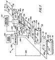
- FIG. 7 there is shown a third embodiment of the present invention for printing image 20 on first receiver 30 and second receiver 40.
- This third embodiment of the invention is substantially similar to the second embodiment of the invention, except that a first print head 70a, having the previously mentioned first orientation N1, and a second print head 70b, having the previously mentioned second orientation N2, are provided. Also provided are a first platen 180a and a second platen 180b associated with their respective first print head 70a and second print head 70b.
- connecting reservoir 120 with print heads 70a and 70b are conduits 125a and 125b for supplying ink to print heads 70a and 70b, respectively.
- first print head 70a will print image 20 on first receiver 30 in substantially the same manner as the print head 70 belonging to the first embodiment of the invention.
- second print head 70b will print image 20 on second receiver 40 in substantially the same manner as the print head 70 belonging to the first embodiment of the invention.
- An advantage of this third embodiment of the invention is that if one print head (i.e., either print head 70a or print head 70b) malfunctions and is taken out of service, the other print head may be used to print on receivers 30/40 by suitably operating controller 220.
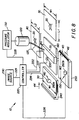
- a fourth embodiment of the present invention for printing image 20 on first receiver 30 and second receiver 40.
- This fourth embodiment of the invention is similar to the first embodiment of the invention, except that first receiver supply 55 and second receiver supply 65, which in the first embodiment are continuous rolls of receiver, are replaced by a first receiver supply tray 240 and a second receiver supply tray 250, respectively.
- First tray 240 holds a supply of cuts sheets of first receiver 30 therein and second tray 250 holds a supply of cut sheets of second receiver 40 therein.
- first rollers 160a/b of the first embodiment are replaced by a motorized first picker feed roller 260a capable of intimately engaging individual sheets of first receiver 30 in order to feed the sheets to print head 70.
- second rollers 170a/b of the first embodiment are replaced by a motorized second picker feed roller 260b capable of intimately engaging individual sheets of second receiver 40 in order to feed the sheets to print head 70.
- Each of picker feed rollers 260a/b are connected to controller 220, such as by means of previously mentioned second wire 224 and third wire 226, respectively, for controlling operation of feed rollers 260a/b.
- an advantage of the preferred embodiment (see Fig. 1) of the present invention is that a single print head is used to print images on a first sized receiver and on a second sized receiver without reorienting the receivers or changing-out the print head to a different sized print head.
- the receivers need not be reoriented because substantially the same movement of the print head is used to print the image on either receiver.
- the print head need not be changed-out because only a single print head is needed.
- Another advantage of the present invention is that high printing productivity is obtained. High printing productivity results when P1>W1 without losing the format flexibility that results when P1 ⁇ W2. This is preferable to having two print heads, where P1 > W1 and P2 ⁇ W2, P1 and P2 being oriented perpendicular to each other.
- the present invention has been disclosed with reference to use with an inkjet printer, the invention may also be used with other types of printers, such as thermal dye printers and laser printers or whenever it is desirable to print images on different sized receivers without reorienting the receivers or changing-out the print head to a different size print head.
Landscapes
- Ink Jet (AREA)
- Handling Of Sheets (AREA)
- Handling Of Continuous Sheets Of Paper (AREA)
Applications Claiming Priority (2)
| Application Number | Priority Date | Filing Date | Title |
|---|---|---|---|
| US358085 | 1994-12-15 | ||
| US09/358,085 US6361163B1 (en) | 1999-07-21 | 1999-07-21 | Inkjet printer, and method of assembling the printer, for printing an image on a first receiver and on a second receiver |
Publications (2)
| Publication Number | Publication Date |
|---|---|
| EP1070595A1 true EP1070595A1 (fr) | 2001-01-24 |
| EP1070595B1 EP1070595B1 (fr) | 2003-04-02 |
Family
ID=23408250
Family Applications (1)
| Application Number | Title | Priority Date | Filing Date |
|---|---|---|---|
| EP00202476A Expired - Lifetime EP1070595B1 (fr) | 1999-07-21 | 2000-07-12 | Procédé former une image sur un premier et un second receveur |
Country Status (4)
| Country | Link |
|---|---|
| US (1) | US6361163B1 (fr) |
| EP (1) | EP1070595B1 (fr) |
| JP (1) | JP2001063030A (fr) |
| DE (1) | DE60001880T2 (fr) |
Cited By (1)
| Publication number | Priority date | Publication date | Assignee | Title |
|---|---|---|---|---|
| SG122813A1 (en) * | 2003-01-24 | 2006-06-29 | Seiko Epson Corp | Printing apparatus and printing method |
Families Citing this family (12)
| Publication number | Priority date | Publication date | Assignee | Title |
|---|---|---|---|---|
| US6704553B1 (en) * | 1997-10-08 | 2004-03-09 | Thomas M. Eubanks | System and method for providing automatic tuning of a radio receiver and for providing automatic control of a CD/tape player |
| FR2814840B1 (fr) * | 2000-09-29 | 2002-12-27 | Neopost Ind | Machine d'affranchissement a haut debit |
| JP4599845B2 (ja) * | 2003-01-24 | 2010-12-15 | セイコーエプソン株式会社 | 印刷装置 |
| JP4669339B2 (ja) * | 2003-01-24 | 2011-04-13 | セイコーエプソン株式会社 | 印刷装置 |
| JP4947125B2 (ja) * | 2003-01-24 | 2012-06-06 | セイコーエプソン株式会社 | 印刷装置 |
| AU2004203127B2 (en) * | 2003-08-22 | 2006-06-29 | Seiko Epson Corporation | Printing apparatus and printing method |
| US6988842B2 (en) * | 2003-09-30 | 2006-01-24 | Pitney Bowes Inc. | Method and apparatus for continuous high speed digital metering using multiple print heads |
| JP4720161B2 (ja) * | 2004-12-01 | 2011-07-13 | セイコーエプソン株式会社 | 複合処理装置及びその制御方法 |
| US7775732B2 (en) * | 2006-11-30 | 2010-08-17 | International Business Machines Corporation | Multi-roll paper supply for printer |
| US8359192B2 (en) | 2008-11-19 | 2013-01-22 | Lemi Technology, Llc | System and method for internet radio station program discovery |
| CN102712195A (zh) * | 2010-01-20 | 2012-10-03 | 株式会社御牧工程 | 图案形成装置 |
| JP2012206497A (ja) | 2011-03-15 | 2012-10-25 | Seiko Epson Corp | 複合型印刷装置 |
Citations (4)
| Publication number | Priority date | Publication date | Assignee | Title |
|---|---|---|---|---|
| EP0288089A2 (fr) * | 1987-04-23 | 1988-10-26 | Brother Kogyo Kabushiki Kaisha | Dispositif de transport du papier dans un dispositif d'enregistrement |
| US5668581A (en) * | 1993-10-27 | 1997-09-16 | Mita Industrial Co., Ltd. | Ink jet printing apparatus |
| EP0841180A2 (fr) * | 1996-11-07 | 1998-05-13 | Brother Kogyo Kabushiki Kaisha | Appareil d'enregistrement |
| EP0914960A2 (fr) * | 1997-10-17 | 1999-05-12 | Brother Kogyo Kabushiki Kaisha | Dispositif d'enregistrement d'images comportant und cassette de bobine amovible |
Family Cites Families (8)
| Publication number | Priority date | Publication date | Assignee | Title |
|---|---|---|---|---|
| DE3341399A1 (de) | 1983-11-15 | 1985-05-23 | Siemens AG, 1000 Berlin und 8000 München | Verfahren zum erhoehen der aufloesung bei einer tintenmosaikschreibeinrichtung sowie anordnung zur durchfuehrung des verfahrens |
| US4709247A (en) | 1986-12-22 | 1987-11-24 | Eastman Kodak Company | High resolution, print/cartridge ink, jet printer |
| JPH04197762A (ja) * | 1990-11-29 | 1992-07-17 | Nec Corp | プリンタ装置 |
| US5880757A (en) | 1991-11-04 | 1999-03-09 | Hewlett-Packard Company | Print resolution enhancement by adjusting printhead position |
| US5348407A (en) | 1992-05-19 | 1994-09-20 | Hewlett-Packard Company | Snap-on control panel |
| DE69432964T2 (de) | 1993-05-03 | 2004-06-03 | Hewlett-Packard Co. (N.D.Ges.D.Staates Delaware), Palo Alto | Gesteigerte Druckauflösung in der Ablaufachse des Wagens eines Tintenstrahldruckers |
| US5883644A (en) | 1993-10-29 | 1999-03-16 | Hewlett-Packard Company | Resolution-dependent and color-dependent print masking |
| US5870117A (en) | 1997-01-21 | 1999-02-09 | Xerox Corporation | Liquid ink printer including a camming printhead to enable increased resolution printing |
-
1999
- 1999-07-21 US US09/358,085 patent/US6361163B1/en not_active Expired - Fee Related
-
2000
- 2000-07-12 EP EP00202476A patent/EP1070595B1/fr not_active Expired - Lifetime
- 2000-07-12 DE DE60001880T patent/DE60001880T2/de not_active Expired - Lifetime
- 2000-07-19 JP JP2000219407A patent/JP2001063030A/ja active Pending
Patent Citations (4)
| Publication number | Priority date | Publication date | Assignee | Title |
|---|---|---|---|---|
| EP0288089A2 (fr) * | 1987-04-23 | 1988-10-26 | Brother Kogyo Kabushiki Kaisha | Dispositif de transport du papier dans un dispositif d'enregistrement |
| US5668581A (en) * | 1993-10-27 | 1997-09-16 | Mita Industrial Co., Ltd. | Ink jet printing apparatus |
| EP0841180A2 (fr) * | 1996-11-07 | 1998-05-13 | Brother Kogyo Kabushiki Kaisha | Appareil d'enregistrement |
| EP0914960A2 (fr) * | 1997-10-17 | 1999-05-12 | Brother Kogyo Kabushiki Kaisha | Dispositif d'enregistrement d'images comportant und cassette de bobine amovible |
Cited By (1)
| Publication number | Priority date | Publication date | Assignee | Title |
|---|---|---|---|---|
| SG122813A1 (en) * | 2003-01-24 | 2006-06-29 | Seiko Epson Corp | Printing apparatus and printing method |
Also Published As
| Publication number | Publication date |
|---|---|
| DE60001880D1 (de) | 2003-05-08 |
| US6361163B1 (en) | 2002-03-26 |
| EP1070595B1 (fr) | 2003-04-02 |
| JP2001063030A (ja) | 2001-03-13 |
| DE60001880T2 (de) | 2003-12-24 |
Similar Documents
| Publication | Publication Date | Title |
|---|---|---|
| EP1070595B1 (fr) | Procédé former une image sur un premier et un second receveur | |
| EP0409596B1 (fr) | Appareil d'enregistrement à jet d'encre | |
| JP5617573B2 (ja) | 画像形成装置 | |
| US6682190B2 (en) | Controlling media curl in print-zone | |
| US20050095046A1 (en) | Platen having channels and method for the same | |
| US6938969B2 (en) | Image recording method and apparatus | |
| US9242486B2 (en) | Printing apparatus for printing on a print substrate | |
| JPH05201081A (ja) | シート給送装置及び前記シート給送装置を用いた記録装置 | |
| JP2000135825A (ja) | 媒体を抑制するハ―ドコピ―装置および方法 | |
| JP2002544010A (ja) | 印字ヘッドの稼働率の向上 | |
| US7246962B2 (en) | Exit roller system for an imaging apparatus | |
| JP3902490B2 (ja) | 画像記録装置 | |
| US8500236B2 (en) | Computer based method and system for adjusting page placement on a continuous feed print engine | |
| US7287922B2 (en) | Exit roller system for an imaging apparatus including backup rollers configured to reduce tracking | |
| JPH0516474A (ja) | ロール紙カートリツジおよび該ロール紙カートリツジを備えた記録装置 | |
| JP3778083B2 (ja) | インクジェット記録装置 | |
| JP2003266840A (ja) | ノートや布などの非平面状被記録体の記録補助具 | |
| JPH0516476A (ja) | ロール紙カートリツジおよび該ロール紙カートリツジを備えた記録装置 | |
| JP3278344B2 (ja) | インクジェット方式画像形成装置 | |
| JP2011037043A (ja) | 印刷機構、サーマルプリンタ | |
| JP3741093B2 (ja) | インクジェット式プリンタ | |
| JP3319932B2 (ja) | インクジェット方式画像形成装置 | |
| JP2022036478A (ja) | 印刷装置、印刷装置の制御方法 | |
| JP4186803B2 (ja) | プリント装置およびプリント方法 | |
| JPH08333044A (ja) | 記録装置および該装置を備えた情報処理システム |
Legal Events
| Date | Code | Title | Description |
|---|---|---|---|
| PUAI | Public reference made under article 153(3) epc to a published international application that has entered the european phase |
Free format text: ORIGINAL CODE: 0009012 |
|
| AK | Designated contracting states |
Kind code of ref document: A1 Designated state(s): DE FR GB |
|
| AX | Request for extension of the european patent |
Free format text: AL;LT;LV;MK;RO;SI |
|
| 17P | Request for examination filed |
Effective date: 20010705 |
|
| AKX | Designation fees paid |
Free format text: DE FR GB |
|
| 17Q | First examination report despatched |
Effective date: 20010926 |
|
| GRAH | Despatch of communication of intention to grant a patent |
Free format text: ORIGINAL CODE: EPIDOS IGRA |
|
| RTI1 | Title (correction) |
Free format text: METHOD OF PRINTING AN IMAGE ON A FIRST RECEIVER AND ON A SECOND RECEIVER |
|
| GRAH | Despatch of communication of intention to grant a patent |
Free format text: ORIGINAL CODE: EPIDOS IGRA |
|
| GRAA | (expected) grant |
Free format text: ORIGINAL CODE: 0009210 |
|
| AK | Designated contracting states |
Designated state(s): DE FR GB |
|
| REG | Reference to a national code |
Ref country code: GB Ref legal event code: FG4D |
|
| REF | Corresponds to: |
Ref document number: 60001880 Country of ref document: DE Date of ref document: 20030508 Kind code of ref document: P |
|
| ET | Fr: translation filed | ||
| PLBE | No opposition filed within time limit |
Free format text: ORIGINAL CODE: 0009261 |
|
| STAA | Information on the status of an ep patent application or granted ep patent |
Free format text: STATUS: NO OPPOSITION FILED WITHIN TIME LIMIT |
|
| 26N | No opposition filed |
Effective date: 20040105 |
|
| PGFP | Annual fee paid to national office [announced via postgrant information from national office to epo] |
Ref country code: FR Payment date: 20060705 Year of fee payment: 7 |
|
| REG | Reference to a national code |
Ref country code: FR Ref legal event code: ST Effective date: 20080331 |
|
| PG25 | Lapsed in a contracting state [announced via postgrant information from national office to epo] |
Ref country code: FR Free format text: LAPSE BECAUSE OF NON-PAYMENT OF DUE FEES Effective date: 20070731 |
|
| PGFP | Annual fee paid to national office [announced via postgrant information from national office to epo] |
Ref country code: GB Payment date: 20120625 Year of fee payment: 13 |
|
| PGFP | Annual fee paid to national office [announced via postgrant information from national office to epo] |
Ref country code: DE Payment date: 20120731 Year of fee payment: 13 |
|
| GBPC | Gb: european patent ceased through non-payment of renewal fee |
Effective date: 20130712 |
|
| PG25 | Lapsed in a contracting state [announced via postgrant information from national office to epo] |
Ref country code: DE Free format text: LAPSE BECAUSE OF NON-PAYMENT OF DUE FEES Effective date: 20140201 Ref country code: GB Free format text: LAPSE BECAUSE OF NON-PAYMENT OF DUE FEES Effective date: 20130712 |
|
| REG | Reference to a national code |
Ref country code: DE Ref legal event code: R119 Ref document number: 60001880 Country of ref document: DE Effective date: 20140201 |