EP1070801A2 - Tragsystem aus Gitterträger und Profilholz - Google Patents
Tragsystem aus Gitterträger und Profilholz Download PDFInfo
- Publication number
- EP1070801A2 EP1070801A2 EP00113642A EP00113642A EP1070801A2 EP 1070801 A2 EP1070801 A2 EP 1070801A2 EP 00113642 A EP00113642 A EP 00113642A EP 00113642 A EP00113642 A EP 00113642A EP 1070801 A2 EP1070801 A2 EP 1070801A2
- Authority
- EP
- European Patent Office
- Prior art keywords
- wood
- chord
- lattice girder
- rods
- support system
- Prior art date
- Legal status (The legal status is an assumption and is not a legal conclusion. Google has not performed a legal analysis and makes no representation as to the accuracy of the status listed.)
- Granted
Links
Images
Classifications
-
- E—FIXED CONSTRUCTIONS
- E04—BUILDING
- E04C—STRUCTURAL ELEMENTS; BUILDING MATERIALS
- E04C5/00—Reinforcing elements, e.g. for concrete; Auxiliary elements therefor
- E04C5/01—Reinforcing elements of metal, e.g. with non-structural coatings
- E04C5/06—Reinforcing elements of metal, e.g. with non-structural coatings of high bending resistance, i.e. of essentially three-dimensional [3D] extent, e.g. lattice girders
- E04C5/065—Light-weight girders, e.g. with precast parts
-
- E—FIXED CONSTRUCTIONS
- E04—BUILDING
- E04C—STRUCTURAL ELEMENTS; BUILDING MATERIALS
- E04C3/00—Structural elongated elements designed for load-supporting
- E04C3/02—Joists; Girders, trusses, or trusslike structures, e.g. prefabricated; Lintels; Transoms; Braces
- E04C3/29—Joists; Girders, trusses, or trusslike structures, e.g. prefabricated; Lintels; Transoms; Braces built-up from parts of different material, i.e. composite structures
- E04C3/292—Joists; Girders, trusses, or trusslike structures, e.g. prefabricated; Lintels; Transoms; Braces built-up from parts of different material, i.e. composite structures the materials being wood and metal
-
- E—FIXED CONSTRUCTIONS
- E04—BUILDING
- E04C—STRUCTURAL ELEMENTS; BUILDING MATERIALS
- E04C5/00—Reinforcing elements, e.g. for concrete; Auxiliary elements therefor
- E04C5/01—Reinforcing elements of metal, e.g. with non-structural coatings
- E04C5/06—Reinforcing elements of metal, e.g. with non-structural coatings of high bending resistance, i.e. of essentially three-dimensional [3D] extent, e.g. lattice girders
Definitions
- the invention relates to a support system consisting of a lattice girder and a Profiled wood according to the preamble of claim 1.
- lattice girders are used as reinforcement for concrete slabs. she allow the creation of self-supporting panels that can be used as roof, wall or Floor elements can be used.
- the lattice girders have one bottom flange running through the plate and one outside the plate trending top chord. The upper and lower chords are connected to each other via diagonal bars connected.
- Such lattice girders are continuously manufactured industrially, whereby the diagonal bars usually consist of a meandering wire, which is laterally welded to the upper chord and lower chord.
- a U-profile formed from sheet metal are provided to secure the attachment of the To produce profiled wood on the lattice girder or a made of wood Knagge, which is fastened to the underside of the profile wood by screw fastening becomes. With the help of the claw a lateral shifting of the profile wood can be relative to the lattice girder are prevented.
- the invention has for its object one of a lattice girder and one Profilholz to create an existing support system that is simple industrial can be manufactured and provides high load capacities regardless of the type of application.
- the top chord of the lattice girder is opposite the vertices of the arch sections offset inwards towards the lower chord rods arranged.
- the arch sections of the diagonal bars protruding over the top chord engage in correspondingly spaced recesses in the profile wood a, which accommodate the arc sections so that a relative displacement is essentially prevented.
- At least one mounting pin is placed across the Profiled wood led below an arch section, so that also in the direction of Lattice girders are provided with a sufficient holding force of the profiled wood.
- the recesses are preferably complementary to the outer contour of the lattice girder shaped in the area of the arc sections so that this section of the lattice girder is secured against movement.
- a lifting of the profile wood is, as already mentioned, prevented by the cross pin, the z. B. from one Screw, a bolt, a nail or the like. Can be formed.
- the profile wood rests on the top chord, so that a distribution of the Contact forces on the profile wood evenly over the length of the lattice girder he follows.
- Both the lattice girder construction can be manufactured in mechanical engineering as well as the shape of the profiled wood with high dimensional accuracy in 1/10 mm Preserved area.
- the profiled wood is put over the diagonal bars, due to the high accuracy of fit a high degree of thrust absorption between diagonals and profiled wood is reached.
- the fastening pin prevents the profile wood from being lifted upwards, for example through the action of wind forces or suction in the roof construction.
- the fastening pin with the lower edge of the arch section in contact brought there is also a contact pressure between profile wood and Top chord.
- the lattice girder When using the lattice girder for wall elements, they can be both horizontal as well as used in a vertical arrangement. When using of suspended ceiling constructions offers the fastening of the profiled wood the lattice girder a high degree of stability of the ceiling construction.
- the carrying system according to the invention can be manufactured using simple means, especially on an industrial level with a high degree of automation and high quality.
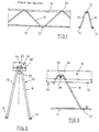
- a lattice girder 30 is shown, which differs from that according to FIG differs. As far as matching parts are used, they will also provided with the same reference numerals. It can be seen from FIGS. 2 and 3 that the Upper chord 32 is lower than the arc sections 20 of the diagonal bars 16, 18. Im concrete embodiment corresponds to the distance, for example, 1.5 cm.
- a profiled wood 34 with a rectangular cross section is arranged above the upper chord 32.
- the profile wood 34 has a number of recesses on the underside which are drawn in dashed lines at 36. As can be seen from Fig. 3, corresponds to Shape of the recess the course of the arc section 20.
- the distance between the recesses 36 corresponds to the distance between the arc sections 20, insofar as they are over the Extend top chord 32.
- the recesses 36 also adapted to the inclined arrangement of the diagonal bars 16, 18. So that's it recorded area of the lattice girder 30 almost positively, so that Movements in the plane of the profiled wood 34 are not possible. With the bottom the profile wood 34 lies on the top chord 32.
- the profiled wood 34 which can also be referred to as a crossbar, is used for attachment of battens, for example roof battens for covering a roof, for the Attachment of an interior lining, a floor or the like.
- a nail 38 is struck across the profile wood 34, which is below the Arch sections 20 abuts the lower edge, so that lifting off the profile wood 34 is prevented.
Landscapes
- Engineering & Computer Science (AREA)
- Architecture (AREA)
- Structural Engineering (AREA)
- Civil Engineering (AREA)
- Chemical & Material Sciences (AREA)
- Composite Materials (AREA)
- Life Sciences & Earth Sciences (AREA)
- Wood Science & Technology (AREA)
- Rod-Shaped Construction Members (AREA)
- Chemical And Physical Treatments For Wood And The Like (AREA)
- Conveying And Assembling Of Building Elements In Situ (AREA)
- Supports For Plants (AREA)
- Joining Of Building Structures In Genera (AREA)
- Forms Removed On Construction Sites Or Auxiliary Members Thereof (AREA)
Abstract
Description
- Fig. 1
- zeigt in Seitenansicht und Endansicht einen herkömmlichen Gitterträger, wie er z. B. bei selbsttragenden Dachtafeln verwendet wird.
- Fig. 2
- zeigt eine Endansicht eines Gitterträgers nach der Erfindung.
- Fig. 3
- zeigt einen Teil einer Seitenansicht des Gitterträgers nach Fig. 2.
Claims (4)
- Tragsystem aus einem Gitterträger, der zwei parallele den Untergurt bildende Stäbe und einen den Obergurt bildenden Stab aufweist, wobei die Untergurtstäbe mit dem Obergurtstab über Diagonalstäbe verbunden sind, die ihrerseits an den Enden über Bogenabschnitte miteinander verbunden sind, und einem Profilholz, das auf der Oberseite des Obergurts angeordnet und mit Hilfe von Befestigungsmitteln befestigt ist, dadurch gekennzeichnet, daß der Obergurt (32) gegenüber den Scheiteln der Bogenabschnitte (20) nach innen zu den Untergurtstäben (10, 12) hin versetzt verläuft, im Profilholz (34) beabstandet Ausnehmungen (36) geformt sind, welche die Bogenabschnitte (20) so aufnehmen, daß eine Relativverschiebung im wesentlichen verhindert ist, und mindestens ein Befestigungsstift (38) innerhalb eines Bogenabschnitts (20) quer zur Längsachse des Profilholzes (34) geführt ist.
- Tragsystem nach Anspruch 1, dadurch gekennzeichnet, daß die Ausnehmungen (36) komplementär zur Bogenform der Bogenabschnitte (36) geformt sind.
- Tragsystem nach Anspruch 1 oder 2, dadurch gekennzeichnet, daß das Profilholz (34) auf dem Obergurt (32) aufliegt.
- Tragsystem nach einem der Ansprüche 1 bis 3, dadurch gekennzeichnet, daß der Befestigungsstift (38) an der Innenseite der Bogenabschnitte (20) anliegt.
Applications Claiming Priority (2)
| Application Number | Priority Date | Filing Date | Title |
|---|---|---|---|
| DE19933101A DE19933101C1 (de) | 1999-07-15 | 1999-07-15 | Tragsystem aus Gitterträger und Profilholz |
| DE19933101 | 1999-07-15 |
Publications (3)
| Publication Number | Publication Date |
|---|---|
| EP1070801A2 true EP1070801A2 (de) | 2001-01-24 |
| EP1070801A3 EP1070801A3 (de) | 2001-02-07 |
| EP1070801B1 EP1070801B1 (de) | 2002-09-18 |
Family
ID=7914840
Family Applications (1)
| Application Number | Title | Priority Date | Filing Date |
|---|---|---|---|
| EP00113642A Expired - Lifetime EP1070801B1 (de) | 1999-07-15 | 2000-06-28 | Tragsystem aus Gitterträger und Profilholz |
Country Status (9)
| Country | Link |
|---|---|
| EP (1) | EP1070801B1 (de) |
| AT (1) | ATE224491T1 (de) |
| CZ (1) | CZ292962B6 (de) |
| DE (2) | DE19933101C1 (de) |
| ES (1) | ES2183765T3 (de) |
| HU (1) | HU222530B1 (de) |
| PL (1) | PL341456A1 (de) |
| PT (1) | PT1070801E (de) |
| SK (1) | SK10292000A3 (de) |
Cited By (1)
| Publication number | Priority date | Publication date | Assignee | Title |
|---|---|---|---|---|
| CN111576737A (zh) * | 2019-05-31 | 2020-08-25 | 成都辟思航空科技有限公司 | 一种整体式无焊接格构柱 |
Citations (3)
| Publication number | Priority date | Publication date | Assignee | Title |
|---|---|---|---|---|
| EP0494612A1 (de) | 1991-01-11 | 1992-07-15 | SÜBA-Cooperation Gesellschaft für Bauforschung, Bauentwicklung und Franchising mbH | Dachtafel für geneigte Dächer |
| DE29806562U1 (de) | 1998-04-09 | 1998-08-27 | Maack, Peter, Dr.-Ing., 21376 Salzhausen | Gitterträger, insbesondere für Dachtafeln |
| DE19743846A1 (de) | 1997-10-04 | 1999-06-02 | Peter Dr Ing Maack | Sattel- oder Walmdach |
Family Cites Families (9)
| Publication number | Priority date | Publication date | Assignee | Title |
|---|---|---|---|---|
| DE382045C (de) * | 1920-11-21 | 1923-09-28 | Jakob Melles | Raeumliches Baugebilde aus Rundraehten |
| DE810188C (de) * | 1949-12-13 | 1951-08-06 | Hans Vollmar | Fachwerktraeger mit zweiteiligem hoelzernem Ober- und Untergurt |
| DE1269324B (de) * | 1962-06-09 | 1968-05-30 | Walter Haslinger | Raeumlicher Fachwerktraeger |
| FR2191001B1 (de) * | 1972-06-30 | 1974-10-25 | Neunkirchen France | |
| JPS6319660B2 (de) * | 1978-12-19 | 1988-04-23 | Furerena Ab | |
| SE8401475L (sv) * | 1984-03-16 | 1985-09-17 | Lars Stalin Konsulter Ab | Truss-webb |
| AU8231087A (en) * | 1986-10-30 | 1988-05-25 | Stalin Konsulter A.B. | A beam and a method of producing the same |
| SE461538B (sv) * | 1987-07-03 | 1990-02-26 | Fundia Bygg Ab | Gallerbalk |
| SE502301C2 (sv) * | 1991-12-02 | 1995-10-02 | Resaro Ab | Balk med trådliv |
-
1999
- 1999-07-15 DE DE19933101A patent/DE19933101C1/de not_active Expired - Fee Related
-
2000
- 2000-06-28 AT AT00113642T patent/ATE224491T1/de not_active IP Right Cessation
- 2000-06-28 ES ES00113642T patent/ES2183765T3/es not_active Expired - Lifetime
- 2000-06-28 PT PT00113642T patent/PT1070801E/pt unknown
- 2000-06-28 DE DE50000514T patent/DE50000514D1/de not_active Expired - Lifetime
- 2000-06-28 EP EP00113642A patent/EP1070801B1/de not_active Expired - Lifetime
- 2000-07-06 SK SK1029-2000A patent/SK10292000A3/sk unknown
- 2000-07-13 PL PL00341456A patent/PL341456A1/xx not_active IP Right Cessation
- 2000-07-14 CZ CZ20002619A patent/CZ292962B6/cs not_active IP Right Cessation
- 2000-07-14 HU HU0002635A patent/HU222530B1/hu not_active IP Right Cessation
Patent Citations (3)
| Publication number | Priority date | Publication date | Assignee | Title |
|---|---|---|---|---|
| EP0494612A1 (de) | 1991-01-11 | 1992-07-15 | SÜBA-Cooperation Gesellschaft für Bauforschung, Bauentwicklung und Franchising mbH | Dachtafel für geneigte Dächer |
| DE19743846A1 (de) | 1997-10-04 | 1999-06-02 | Peter Dr Ing Maack | Sattel- oder Walmdach |
| DE29806562U1 (de) | 1998-04-09 | 1998-08-27 | Maack, Peter, Dr.-Ing., 21376 Salzhausen | Gitterträger, insbesondere für Dachtafeln |
Cited By (2)
| Publication number | Priority date | Publication date | Assignee | Title |
|---|---|---|---|---|
| CN111576737A (zh) * | 2019-05-31 | 2020-08-25 | 成都辟思航空科技有限公司 | 一种整体式无焊接格构柱 |
| CN111576737B (zh) * | 2019-05-31 | 2022-01-18 | 成都辟思航空科技有限公司 | 一种整体式无焊接格构柱 |
Also Published As
| Publication number | Publication date |
|---|---|
| SK10292000A3 (sk) | 2001-01-18 |
| HUP0002635A2 (hu) | 2001-05-28 |
| CZ20002619A3 (cs) | 2001-03-14 |
| ATE224491T1 (de) | 2002-10-15 |
| CZ292962B6 (cs) | 2004-01-14 |
| PT1070801E (pt) | 2003-02-28 |
| DE50000514D1 (de) | 2002-10-24 |
| HU222530B1 (hu) | 2003-08-28 |
| EP1070801B1 (de) | 2002-09-18 |
| PL341456A1 (en) | 2001-01-29 |
| EP1070801A3 (de) | 2001-02-07 |
| ES2183765T3 (es) | 2003-04-01 |
| DE19933101C1 (de) | 2001-05-23 |
| HU0002635D0 (en) | 2000-09-28 |
| HUP0002635A3 (en) | 2002-04-29 |
Similar Documents
| Publication | Publication Date | Title |
|---|---|---|
| DD299670A5 (de) | Raeumliche gittertragwerkskonstruktion und verfahren zu deren herstellung | |
| EP2050887B1 (de) | Gitterträger | |
| DE69410077T2 (de) | Vorgefertigter stahlbetonverbundträger | |
| EP0164330A2 (de) | Stahlbetondecke | |
| DE69516395T2 (de) | Verankerungsvorrichtung für einen träger | |
| EP0411113B1 (de) | Treppe | |
| CH651095A5 (de) | Bewehrungselement zur uebertragung von querkraeften in plattenartigen traggliedern, z.b. flachdecken. | |
| EP1070801B1 (de) | Tragsystem aus Gitterträger und Profilholz | |
| EP0563707A1 (de) | Schalungstafel | |
| DE3874539T2 (de) | Gittertraeger. | |
| DE20011318U1 (de) | Hammerplatten-Winkelelement | |
| DE9214426U1 (de) | Stahlträger für eine Blechverbunddecke | |
| DE2627840A1 (de) | Ein vorgespanntes bauelement mit holzkonstruktion | |
| DE29913348U1 (de) | Tragsystem aus Gitterträger und Profilholz | |
| EP3617415B1 (de) | Durchstanzbewehrungselement und bauwerk mit einer platte mit einem durchstanzbewehrungselement | |
| EP1229180A2 (de) | Sattel- oder Walmdach | |
| DE1759411A1 (de) | Einzelplatte zur Abdeckung von Traggeruesten od.dgl. | |
| EP0047550B1 (de) | Rechteckförmiges Schalungselement | |
| DE2422771C3 (de) | Raumfachwerk | |
| EP1223259A1 (de) | Bewhrung für auf Stützen aufgelagerte Flachdecken, Schubbewehrungselement sowie ein Verfahren zur Herstellung einer Bewehrung | |
| DE19530572A1 (de) | Gebäude-Tragkonstruktion | |
| DE29806562U1 (de) | Gitterträger, insbesondere für Dachtafeln | |
| DE2354694A1 (de) | Quertraeger mit offenem gitter | |
| DE20309548U1 (de) | Segmentträger | |
| DE4405977A1 (de) | Gerüst mit aufeinanderlegbaren Teilen |
Legal Events
| Date | Code | Title | Description |
|---|---|---|---|
| PUAI | Public reference made under article 153(3) epc to a published international application that has entered the european phase |
Free format text: ORIGINAL CODE: 0009012 |
|
| PUAL | Search report despatched |
Free format text: ORIGINAL CODE: 0009013 |
|
| AK | Designated contracting states |
Kind code of ref document: A2 Designated state(s): AT BE CH CY DE DK ES FI FR GB GR IE IT LI LU MC NL PT SE |
|
| AX | Request for extension of the european patent |
Free format text: AL;LT;LV;MK;RO;SI |
|
| AK | Designated contracting states |
Kind code of ref document: A3 Designated state(s): AT BE CH CY DE DK ES FI FR GB GR IE IT LI LU MC NL PT SE |
|
| AX | Request for extension of the european patent |
Free format text: AL;LT;LV;MK;RO;SI |
|
| 17P | Request for examination filed |
Effective date: 20010629 |
|
| AKX | Designation fees paid |
Free format text: AT BE CH CY DE DK ES FI FR GB GR IE IT LI LU MC NL PT SE |
|
| GRAG | Despatch of communication of intention to grant |
Free format text: ORIGINAL CODE: EPIDOS AGRA |
|
| 17Q | First examination report despatched |
Effective date: 20020221 |
|
| GRAG | Despatch of communication of intention to grant |
Free format text: ORIGINAL CODE: EPIDOS AGRA |
|
| GRAH | Despatch of communication of intention to grant a patent |
Free format text: ORIGINAL CODE: EPIDOS IGRA |
|
| GRAH | Despatch of communication of intention to grant a patent |
Free format text: ORIGINAL CODE: EPIDOS IGRA |
|
| GRAA | (expected) grant |
Free format text: ORIGINAL CODE: 0009210 |
|
| AK | Designated contracting states |
Kind code of ref document: B1 Designated state(s): AT BE CH CY DE DK ES FI FR GB GR IE IT LI LU MC NL PT SE |
|
| PG25 | Lapsed in a contracting state [announced via postgrant information from national office to epo] |
Ref country code: GR Free format text: LAPSE BECAUSE OF FAILURE TO SUBMIT A TRANSLATION OF THE DESCRIPTION OR TO PAY THE FEE WITHIN THE PRESCRIBED TIME-LIMIT Effective date: 20020918 Ref country code: IE Free format text: LAPSE BECAUSE OF FAILURE TO SUBMIT A TRANSLATION OF THE DESCRIPTION OR TO PAY THE FEE WITHIN THE PRESCRIBED TIME-LIMIT Effective date: 20020918 |
|
| REF | Corresponds to: |
Ref document number: 224491 Country of ref document: AT Date of ref document: 20021015 Kind code of ref document: T |
|
| REG | Reference to a national code |
Ref country code: GB Ref legal event code: FG4D Free format text: NOT ENGLISH |
|
| REG | Reference to a national code |
Ref country code: CH Ref legal event code: EP |
|
| REG | Reference to a national code |
Ref country code: IE Ref legal event code: FG4D Free format text: GERMAN |
|
| REF | Corresponds to: |
Ref document number: 50000514 Country of ref document: DE Date of ref document: 20021024 |
|
| PG25 | Lapsed in a contracting state [announced via postgrant information from national office to epo] |
Ref country code: DK Free format text: LAPSE BECAUSE OF FAILURE TO SUBMIT A TRANSLATION OF THE DESCRIPTION OR TO PAY THE FEE WITHIN THE PRESCRIBED TIME-LIMIT Effective date: 20021218 Ref country code: SE Free format text: LAPSE BECAUSE OF FAILURE TO SUBMIT A TRANSLATION OF THE DESCRIPTION OR TO PAY THE FEE WITHIN THE PRESCRIBED TIME-LIMIT Effective date: 20021218 |
|
| REG | Reference to a national code |
Ref country code: CH Ref legal event code: NV Representative=s name: ISLER & PEDRAZZINI AG |
|
| GBT | Gb: translation of ep patent filed (gb section 77(6)(a)/1977) |
Effective date: 20030122 |
|
| REG | Reference to a national code |
Ref country code: PT Ref legal event code: SC4A Free format text: AVAILABILITY OF NATIONAL TRANSLATION Effective date: 20021218 |
|
| REG | Reference to a national code |
Ref country code: ES Ref legal event code: FG2A Ref document number: 2183765 Country of ref document: ES Kind code of ref document: T3 |
|
| ET | Fr: translation filed | ||
| PGFP | Annual fee paid to national office [announced via postgrant information from national office to epo] |
Ref country code: PT Payment date: 20030513 Year of fee payment: 4 |
|
| REG | Reference to a national code |
Ref country code: IE Ref legal event code: FD4D Ref document number: 1070801E Country of ref document: IE |
|
| PGFP | Annual fee paid to national office [announced via postgrant information from national office to epo] |
Ref country code: FI Payment date: 20030613 Year of fee payment: 4 |
|
| PG25 | Lapsed in a contracting state [announced via postgrant information from national office to epo] |
Ref country code: LU Free format text: LAPSE BECAUSE OF NON-PAYMENT OF DUE FEES Effective date: 20030628 Ref country code: CY Free format text: LAPSE BECAUSE OF FAILURE TO SUBMIT A TRANSLATION OF THE DESCRIPTION OR TO PAY THE FEE WITHIN THE PRESCRIBED TIME-LIMIT Effective date: 20030628 |
|
| PG25 | Lapsed in a contracting state [announced via postgrant information from national office to epo] |
Ref country code: MC Free format text: LAPSE BECAUSE OF NON-PAYMENT OF DUE FEES Effective date: 20030630 |
|
| PLBE | No opposition filed within time limit |
Free format text: ORIGINAL CODE: 0009261 |
|
| STAA | Information on the status of an ep patent application or granted ep patent |
Free format text: STATUS: NO OPPOSITION FILED WITHIN TIME LIMIT |
|
| 26N | No opposition filed |
Effective date: 20030619 |
|
| PG25 | Lapsed in a contracting state [announced via postgrant information from national office to epo] |
Ref country code: FI Free format text: LAPSE BECAUSE OF NON-PAYMENT OF DUE FEES Effective date: 20040628 |
|
| PG25 | Lapsed in a contracting state [announced via postgrant information from national office to epo] |
Ref country code: LI Free format text: LAPSE BECAUSE OF NON-PAYMENT OF DUE FEES Effective date: 20040630 Ref country code: CH Free format text: LAPSE BECAUSE OF NON-PAYMENT OF DUE FEES Effective date: 20040630 |
|
| PGFP | Annual fee paid to national office [announced via postgrant information from national office to epo] |
Ref country code: BE Payment date: 20040713 Year of fee payment: 5 |
|
| PG25 | Lapsed in a contracting state [announced via postgrant information from national office to epo] |
Ref country code: PT Free format text: LAPSE BECAUSE OF NON-PAYMENT OF DUE FEES Effective date: 20041228 |
|
| REG | Reference to a national code |
Ref country code: CH Ref legal event code: PL |
|
| REG | Reference to a national code |
Ref country code: PT Ref legal event code: MM4A Free format text: LAPSE DUE TO NON-PAYMENT OF FEES Effective date: 20041228 |
|
| PG25 | Lapsed in a contracting state [announced via postgrant information from national office to epo] |
Ref country code: BE Free format text: LAPSE BECAUSE OF NON-PAYMENT OF DUE FEES Effective date: 20050630 |
|
| PGFP | Annual fee paid to national office [announced via postgrant information from national office to epo] |
Ref country code: ES Payment date: 20060613 Year of fee payment: 7 |
|
| PGFP | Annual fee paid to national office [announced via postgrant information from national office to epo] |
Ref country code: FR Payment date: 20060627 Year of fee payment: 7 |
|
| PGFP | Annual fee paid to national office [announced via postgrant information from national office to epo] |
Ref country code: GB Payment date: 20060628 Year of fee payment: 7 |
|
| PGFP | Annual fee paid to national office [announced via postgrant information from national office to epo] |
Ref country code: AT Payment date: 20070619 Year of fee payment: 8 |
|
| BERE | Be: lapsed |
Owner name: HAASS VERTRIEBSG.- FUR BAUELEMENTE M.B.H. *HVG Effective date: 20050630 |
|
| PGFP | Annual fee paid to national office [announced via postgrant information from national office to epo] |
Ref country code: IT Payment date: 20070620 Year of fee payment: 8 |
|
| GBPC | Gb: european patent ceased through non-payment of renewal fee |
Effective date: 20070628 |
|
| REG | Reference to a national code |
Ref country code: FR Ref legal event code: ST Effective date: 20080229 |
|
| PG25 | Lapsed in a contracting state [announced via postgrant information from national office to epo] |
Ref country code: GB Free format text: LAPSE BECAUSE OF NON-PAYMENT OF DUE FEES Effective date: 20070628 |
|
| REG | Reference to a national code |
Ref country code: ES Ref legal event code: FD2A Effective date: 20070629 |
|
| PG25 | Lapsed in a contracting state [announced via postgrant information from national office to epo] |
Ref country code: FR Free format text: LAPSE BECAUSE OF NON-PAYMENT OF DUE FEES Effective date: 20070702 |
|
| PG25 | Lapsed in a contracting state [announced via postgrant information from national office to epo] |
Ref country code: ES Free format text: LAPSE BECAUSE OF NON-PAYMENT OF DUE FEES Effective date: 20070629 |
|
| PG25 | Lapsed in a contracting state [announced via postgrant information from national office to epo] |
Ref country code: AT Free format text: LAPSE BECAUSE OF NON-PAYMENT OF DUE FEES Effective date: 20080628 |
|
| PG25 | Lapsed in a contracting state [announced via postgrant information from national office to epo] |
Ref country code: IT Free format text: LAPSE BECAUSE OF NON-PAYMENT OF DUE FEES Effective date: 20080628 |
|
| PGFP | Annual fee paid to national office [announced via postgrant information from national office to epo] |
Ref country code: NL Payment date: 20100622 Year of fee payment: 11 |
|
| PGFP | Annual fee paid to national office [announced via postgrant information from national office to epo] |
Ref country code: DE Payment date: 20100807 Year of fee payment: 11 |
|
| REG | Reference to a national code |
Ref country code: NL Ref legal event code: V1 Effective date: 20120101 |
|
| REG | Reference to a national code |
Ref country code: DE Ref legal event code: R119 Ref document number: 50000514 Country of ref document: DE Effective date: 20120103 |
|
| PG25 | Lapsed in a contracting state [announced via postgrant information from national office to epo] |
Ref country code: DE Free format text: LAPSE BECAUSE OF NON-PAYMENT OF DUE FEES Effective date: 20120103 |
|
| PG25 | Lapsed in a contracting state [announced via postgrant information from national office to epo] |
Ref country code: NL Free format text: LAPSE BECAUSE OF NON-PAYMENT OF DUE FEES Effective date: 20120101 |