EP1070821A2 - Profilé creux en matière plastique - Google Patents
Profilé creux en matière plastique Download PDFInfo
- Publication number
- EP1070821A2 EP1070821A2 EP00110912A EP00110912A EP1070821A2 EP 1070821 A2 EP1070821 A2 EP 1070821A2 EP 00110912 A EP00110912 A EP 00110912A EP 00110912 A EP00110912 A EP 00110912A EP 1070821 A2 EP1070821 A2 EP 1070821A2
- Authority
- EP
- European Patent Office
- Prior art keywords
- profile
- hollow
- hollow plastic
- reinforcement
- air
- Prior art date
- Legal status (The legal status is an assumption and is not a legal conclusion. Google has not performed a legal analysis and makes no representation as to the accuracy of the status listed.)
- Granted
Links
- 239000004033 plastic Substances 0.000 title claims description 83
- 229920003023 plastic Polymers 0.000 title claims description 83
- 230000002787 reinforcement Effects 0.000 claims abstract description 114
- 229910052751 metal Inorganic materials 0.000 claims abstract description 11
- 239000002184 metal Substances 0.000 claims abstract description 11
- 230000003014 reinforcing effect Effects 0.000 claims description 21
- 238000005260 corrosion Methods 0.000 claims description 18
- 238000000576 coating method Methods 0.000 claims description 17
- 230000007797 corrosion Effects 0.000 claims description 16
- 239000011248 coating agent Substances 0.000 claims description 15
- 229910000831 Steel Inorganic materials 0.000 claims description 7
- 239000010959 steel Substances 0.000 claims description 7
- 229910052782 aluminium Inorganic materials 0.000 claims description 3
- XAGFODPZIPBFFR-UHFFFAOYSA-N aluminium Chemical compound [Al] XAGFODPZIPBFFR-UHFFFAOYSA-N 0.000 claims description 3
- 239000012815 thermoplastic material Substances 0.000 claims 1
- 229920001169 thermoplastic Polymers 0.000 abstract 1
- 239000004416 thermosoftening plastic Substances 0.000 abstract 1
- 238000009413 insulation Methods 0.000 description 19
- 238000005457 optimization Methods 0.000 description 9
- 230000005855 radiation Effects 0.000 description 9
- 230000009467 reduction Effects 0.000 description 7
- 238000005452 bending Methods 0.000 description 5
- 230000008901 benefit Effects 0.000 description 5
- 239000000463 material Substances 0.000 description 5
- 238000009825 accumulation Methods 0.000 description 4
- 230000035508 accumulation Effects 0.000 description 4
- 239000000835 fiber Substances 0.000 description 3
- 230000007935 neutral effect Effects 0.000 description 3
- 239000002984 plastic foam Substances 0.000 description 3
- 230000000694 effects Effects 0.000 description 2
- 239000006260 foam Substances 0.000 description 2
- 230000006872 improvement Effects 0.000 description 2
- 238000004519 manufacturing process Methods 0.000 description 2
- 238000000034 method Methods 0.000 description 2
- 241000446313 Lamella Species 0.000 description 1
- 238000010521 absorption reaction Methods 0.000 description 1
- 210000000988 bone and bone Anatomy 0.000 description 1
- 238000004364 calculation method Methods 0.000 description 1
- 238000010276 construction Methods 0.000 description 1
- 230000006735 deficit Effects 0.000 description 1
- 238000005516 engineering process Methods 0.000 description 1
- 239000003000 extruded plastic Substances 0.000 description 1
- 230000002349 favourable effect Effects 0.000 description 1
- 239000011888 foil Substances 0.000 description 1
- 238000003780 insertion Methods 0.000 description 1
- 230000037431 insertion Effects 0.000 description 1
- 238000005259 measurement Methods 0.000 description 1
- 239000004800 polyvinyl chloride Substances 0.000 description 1
- 238000004080 punching Methods 0.000 description 1
- 238000007493 shaping process Methods 0.000 description 1
- 230000009897 systematic effect Effects 0.000 description 1
Images




Classifications
-
- E—FIXED CONSTRUCTIONS
- E06—DOORS, WINDOWS, SHUTTERS, OR ROLLER BLINDS IN GENERAL; LADDERS
- E06B—FIXED OR MOVABLE CLOSURES FOR OPENINGS IN BUILDINGS, VEHICLES, FENCES OR LIKE ENCLOSURES IN GENERAL, e.g. DOORS, WINDOWS, BLINDS, GATES
- E06B3/00—Window sashes, door leaves, or like elements for closing wall or like openings; Layout of fixed or moving closures, e.g. windows in wall or like openings; Features of rigidly-mounted outer frames relating to the mounting of wing frames
- E06B3/04—Wing frames not characterised by the manner of movement
- E06B3/06—Single frames
- E06B3/08—Constructions depending on the use of specified materials
- E06B3/20—Constructions depending on the use of specified materials of plastics
- E06B3/22—Hollow frames
- E06B3/221—Hollow frames with the frame member having local reinforcements in some parts of its cross-section or with a filled cavity
- E06B3/222—Hollow frames with the frame member having local reinforcements in some parts of its cross-section or with a filled cavity with internal prefabricated reinforcing section members inserted after manufacturing of the hollow frame
Definitions
- the invention relates to a plastic hollow profile at least one hollow chamber for receiving a Reinforcement profile according to the preamble of the claim 1.
- Hollow chamber profiles are used for the most diverse Application areas manufactured, e.g. for window frames, Door frames, cable ducts and facades. Will this Hollow chamber profiles exposed to loads, so they bend Profiles noticeably through, which is why they stiffen Reinforcement profiles must be inserted. Reinforcement profiles are usually made of metal, so that the advantage of hollow plastic profiles, a small one Heat conduction between the inside and outside, clearly is reduced. Therefore, one strives in technology that Thermal insulation of hollow plastic profiles with Reinforcing reinforcements without improving theirs reduce mechanical strength to a significant degree.
- German utility model 295 17 037 describes the Applying an insulation layer to a reinforcement insert in order to achieve sound and / or heat insulation.
- German Offenlegungsschrift 4 331 816 proposes that Air chamber between the surrounding walls of the hollow chamber a plastic frame and a reinforcement profile with To fill in plastic foam.
- This plastic foam can in the form of a foam strip on the reinforcement profile glued and together with this into the hollow chamber of the Frame profile are introduced.
- Providing one Foam layer on the outside of a reinforcement profile has the disadvantage, however, that the reinforcement profile must be dimensioned smaller, whereby the Strength gain through the use of a Reinforcement profile is reduced.
- German utility model 297 15 346 describes this Provide one to the inside of the window or door neighboring hollow chamber of the plastic hollow profile and that Inserting a reflective lamella, e.g. of metal with reflecting surface, inside the hollow chamber.
- the invention has for its object a reinforced To propose plastic hollow profile, which is an improved Has thermal insulation, but without the strength of the Sustainably reduce reinforcement.
- the invention is based on the idea that the provision of air chambers transverse to the main heat flow direction has a significantly higher effect than the provision of Air chambers between the side walls of the reinforcement profile and the surrounding walls of the hollow chamber.
- At least one is second air chamber between the surrounding walls of the Hollow chamber and the reinforcement profile parallel to Main heat flow direction provided.
- This measure leaves the thermal resistance continues to improve because plastic is the Heat conducts better than air and therefore the provision of second Air chambers between the plastic hollow profile and the well conductive, metallic reinforcement profile Total heat flow from the warm to the cold side is reduced.
- This proposed further measure to improve Thermal insulation is, however, related to the desired Strength values of the reinforced hollow profile can be seen there the provision of one or two reinforced air chambers a reduction in the reinforcement profile and one Reduction in strength leads.
- the air layer thickness is preferably at least one second air chamber at least 1 mm, preferably 2 to 6 mm. From a comparison of these preferred air layer thicknesses with the air layer thicknesses of the first specified in claim 1 Air chambers it becomes clear that the second air chambers one lower contribution to the thermal insulation of the hollow plastic profile perform and therefore the air layer thicknesses should be less should not to the strength of the reinforcement profile inappropriately decrease. As will be explained later, there are also ways of shaping the Reinforcing profiles to optimize the thermal insulation improve.
- this comprises Hollow plastic profile still one layer less Thermal conductivity, preferably foamed plastic, in the second air chamber (s). This allows you to do that Reinforcement profile made of metal thermally throughout decouple because of a layer of foamed plastic the reinforcement profile in the hollow chamber is stabilized.
- Reinforcement profile made of steel and points on the whole Perimeter outside or outside as well as inside Corrosion protection coating on which an emissivity of below Has 20%.
- This coating for example, by Coil coating / coating can be generated both corrosion protection for the reinforcement profile 4 as well a reflective layer that reflects infrared radiation.
- the emissivity of the Corrosion protection coating below 10%, most preferred in 5% range.
- Reinforcement profile held on the hollow profile by supporting parts which are preferably formed in one piece with the hollow profile are.
- the provision of plastic support parts offers one good decoupling of the metal reinforcement profile from that surrounding plastic profile, since only in the area of the support parts heat conduction from plastic to metal can take place.
- the hollow plastic profile comprises support parts which the reinforcement profile against movement in two directions to back up.
- Finished support parts for example a bridge own, which is from the surrounding wall of the hollow chamber extends inwards, as well as an L-shaped holding profile, assume the function of two separate support parts, since one Movement of the reinforcement profile in two directions is prevented and at the same time a tour for the Inserting the reinforcement profile is provided.
- the Basic idea for the thermal optimization of the support parts is to reduce the number of support parts and to reduce their cross sections, thereby the Heat conduction from the plastic profile to the To keep the reinforcement profile as low as possible.
- a further optimization can be achieved by the Support parts from the surrounding hollow profile perpendicular to Main heat flow direction extend. So even one targeted selection of the location of the support parts for thermal engineering Contribute to the optimization of the entire hollow plastic profile.
- this is Reinforcement profile formed as a rectangular profile, the Air layer thickness of the first air chambers each Air layer thickness of the at least one second air chamber exceeds.
- the first in terms of effective thermal insulation Air chambers have a greater effect than the second air chambers. Therefore, in terms of the geometry of the Reinforcement profile optimal design of the air chambers first air chambers with an air layer thickness of 2 to 12 mm, preferably 3 to 8 mm, without one Construction depth reduction the rigidity of the reinforcement profile decrease, and second air chambers with a smaller one Air layer thickness, which is between 2 and 6 mm.
- this is Reinforcement profile perpendicular to the main heat flow direction reinforced at least in some areas. In doing so, a high Flexural strength around the X axis, which is perpendicular to the Main heat flow direction runs through a high Material accumulation in locations as far from the X axis as possible are generated.
- the reinforcement profile is preferably a double-T profile formed, the connecting web in Main heat flow direction.
- This design too has a high section modulus around the X axis, because here a very high material accumulation from the neutral Fiber is removed.
- care must also be taken be worn that the reinforcement profile as possible has high strength in the Y direction because the Own load absorption of filling elements by the Plastic profile leads to a bend around the Y axis.
- the Y axis is perpendicular to the X axis and in the direction of Main heat flow direction.
- the Connecting bridge of the double-T profile offset from the middle is, so that the two second air layer thicknesses are of different sizes, this connecting bridge is from removes the neutral fiber and also does one Contribution to section modulus with respect to the Y axis.
- this is Reinforcement profile as a double T profile with two Bridges formed, the two Crosspieces are spaced apart.
- a profile with a shape that is in the Cross-section considered is similar to a dog's bone.
- the provision of two connecting bars allows them to be separated from the neutral fiber with respect to the bending moment around the Y axis to space while maintaining a symmetrical Behavior can be established.
- Through the cross section closed form of the profile also becomes another Air chamber generated, which is enclosed by the profile.
- the reinforcement profiles are preferably roll-formed. This Manufacturing process makes it possible to also use reinforcement profiles to produce complex shapes inexpensively and reinforcements at the desired points at the same time to provide the double-layer execution of the profiles.
- Fig. 1 is a base body of a hollow plastic profile shown, which is generally designated by reference number 10 is and is referred to below as a plastic hollow profile becomes.
- the hollow plastic profile generally consists of Polyvinylchloride (PVC) and is used for windows, doors and Facades used. Because of the low bending stiffness of hollow plastic profiles are usually Metal profile inserts used as reinforcement profiles 12. Reinforcement profiles are usually made of steel or Aluminum and are often rectangular tubes, as in Fig. 1st is shown.
- the heat loss flow across the cross section of the profile is done by heat conduction, free convection in the Cavities of the profile as well as by radiation.
- the heat conduction is bad by using conductive plastic for the plastic hollow profile 10 reduced as much as possible.
- the heat conduction in Reduce reinforcement profile by the reinforcement profile 12 is provided with smaller dimensions and along the path of the heat flow to be covered by the plastic profile is increased as possible.
- a reduction in the dimensions of the Reinforcement profile 12 has the disadvantage that the desired strength gain by inserting the Reinforcement profile is reduced. Therefore a suitable compromise between a sufficient Dimensioning of the reinforcement profile 12 and one Improvement in thermal insulation can be found.
- Fig. 1 In the embodiment shown in Fig. 1 are two chambers in the hollow plastic profile, a first closed Chamber facing either the outside or inside of the Profile is arranged and a second chamber 16, in which extend support members 18, which the Hold reinforcement profile 12 and when inserting the Reinforcement profile 12 also serve as a guide.
- the support parts 18 still fulfill another function, namely predetermined distances between the reinforcement profile 12 and the surrounding wall parts of the plastic hollow profile.
- the support parts which are integral with the surrounding wall parts of the plastic hollow profile 10 are formed in the indicated by the arrows Q.
- Main heat flow direction with a different length a or b trained.
- first air chambers 20 are formed between the reinforcement profile 12 and the the chamber 16 surrounding wall 19 of the hollow plastic profile. These first air chambers have a width a, b of 2 to 12 mm and preferably 3 up to 8 mm.
- the first air chambers 20 have been found to be very much greater importance for the overall thermal insulation of the Have profiles than that between the reinforcing profile 12 and the side walls 21 of the hollow plastic profile, i.e. those walls of the hollow plastic profile whose Longitudinal extension parallel to the main heat flow direction runs, arranged second air chambers 22. Still leaves the overall thermal insulation improves by the Use of the rectangular shown in Fig. 1 Reinforcement profile 12 also lateral, second air chambers 22 are provided, but the thickness c is less than that of the first air chambers 20.
- the second air chambers on the side 22 due to the thermal point of view lesser importance of the second air chambers 22 this also can only be provided on one side if it is the require sufficient dimensioning of the reinforcement profile 12 should.
- the reinforcement profile 12 made of steel Corrosion protection coating has a low Possesses emissivity.
- the corrosion protection coating thus serves both corrosion protection and reflection of Infrared radiation.
- the Corrosion protection coatings on the surfaces 23, which to the first air chambers 20 point out on the reinforcement profile upset.
- it is for the entire thermal insulation advantageous, also on the inside of the Reinforcing profile 12 lying surfaces 24 a corresponding corrosion protection coating with less To show emissivity. From a manufacturing perspective like it is also in the sense of complete corrosion protection however, be preferred, all surfaces inside as well as outside of the metal reinforcement profile with a corresponding one To provide corrosion protection coating.
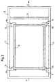
- Fig. 2 shows the reinforcement profile shown in Fig. 1 12, however, the support parts from a thermal point of view were optimized. Since the heat conduction from the room side surrounding plastic hollow profile to the reinforcement profile 12 a thermal optimization can be achieved, by first reducing the number of support parts. Out a comparison of the configuration of the support parts in FIG. 2 with that shown in Fig. 1 follows that, unlike the provision of eight support parts according to FIG. 1 only four Support parts are provided. This already allows same cross-sectional dimension of the heat flow through Heat conduction from the plastic hollow profile 10 to Halve reinforcement profile 12 and vice versa. Another Reduction of the heat flow can be achieved by the Cross sections of the support parts can be reduced. Here too shows a comparison of the representations in Fig. 2 and Fig. 1, that the feet 18a of the support members 18 shown in FIG. 2 one have a smaller cross section, which also the Heat conduction is reduced.
- Support parts 18 can be a single support part through the L-shaped Contact surface with the reinforcement profile inserted into it 12 the gain profile of a movement in two directions prevent, so the number of support parts accordingly can be reduced.
- One last thermal Optimization of the support parts affects the position of the support parts.
- a thermal optimization can also be done by a Extend the heat-conducting paths, which is why Feet 18a of the support members 18 perpendicular to Main heat flow direction are arranged. This cannot more direct heat conduction between the wall 19 of the Plastic hollow profile 10 and the reinforcement profile 12 take place, but it requires a "detour" of the heat flow over the side walls 21 and back towards them the reinforcement profile 12.
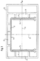
- Fig. 3 shows an alternative embodiment of the Reinforcement profile 12.
- the plastic hollow profile 10 was largely taken from the representation in Fig. 1, it should be clear that this is exemplary only owns.
- the reinforcement profile 12 is roll-formed and on the both ends 12a made of two layers. This will make the Strength of the profile with regard to the moment of inertia related to the X-axis 25 increased by the of the X-axis 25 removed areas of the reinforcement profile 12 targeted material accumulations are provided.
- the one web 12b connecting reinforced end regions is furthermore spaced sufficiently far from the Y axis 24 so that also 24 good with respect to the bending moment about the Y axis Strength values can be achieved. That in Fig.
- Fig. 4 shows an alternative embodiment of the Reinforcement profile in the surrounding plastic hollow profile 10, to clarify the differences again on the Basic geometry according to FIG. 1 was used. How from 4 can be seen, the reinforcement profile 12th non-symmetrical. In principle it is of course also possible, one with respect to the Y axis 25 or X-axis 24 non-symmetrical reinforcement profile 4, but only different ones should be provided in FIG Detailed solutions are displayed side by side.
- the roll-shaped reinforcement profile 12 has again Reinforcement areas 12, which provide for an improved Bending stiffness to the simple in the double-walled area, 12c or multiple 12d are angled.
- the the web 12b connecting double-walled regions is likewise provided with bends, whereby the width c of the second Air chamber 22 is increased in some areas.
- the support parts 18 are not optimized in FIG. 4 shown, but here would be an embodiment of the Offer support parts according to Fig. 2.
- FIG. 5 shows a further embodiment of the one in FIG. 1 shown hollow plastic profile 10 with a special Shape of the reinforcement profile 12.
- the representation in 5 shows only one half of the plastic hollow profile 10, the second half is a mirror image of the one shown X-axis 25.
- the profile shown in FIG. 5 also has Reinforcement areas 12a, in the area of which both Material accumulation as well as a stiffening of the Reinforcement profile 12 is present.
- the connection areas 12b are in each case one layer between the reinforcement regions 12a executed, two in the main heat flow direction Connection areas 12b run.
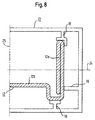
- the air layer thickness c the second air chambers 22 is due to this special design of the reinforcement profile 12 larger, but still a sufficient rigidity of the reinforcement profile 12 due to of the two running parallel to the main heat flow direction Connection areas 12b is given. Even in the case of Reinforcement profile 12 could support parts 18 in one Be designed and arranged in the manner shown in FIG. 2 is shown. This and a slightly different one Design of the reinforcement profile 12 is shown in Fig. 6, in the top of the drawing plane a support member 18 with an L-shaped Support pad is shown, the fixation of the Reinforcement profile in both the main heat flow direction and also ensures perpendicular to this.
- FIG. 7 shows yet another embodiment of a Reinforcement profile 12 in a hollow plastic profile 10, the is only shown as a half-section and symmetrical to the X-axis 25 can be formed.
- the one shown here Reinforcement profile has a double wall Gain region 12a, which in the from the X-axis 25th distant area is arranged and thus to a high Moment of inertia with respect to the X axis.
- the two Gain areas 12a are formed by a single one Connection area 12b connected to each other, the middle between the side walls 21 of the hollow plastic profile 10 runs and also held and guided on support members 18 becomes.
- the two in the drawing plane in Fig. 7 arranged below support members by a single support part corresponding to the one on top of the Support part arranged in the plane of the drawing can be replaced.
- the embodiment in FIG. 7 again has the advantage that due to the small cross-sectional area of the Connection area 12b only a reduced heat conduction in Main heat flow direction through the reinforcement profile 12 he follows.
- FIG. 8 shows a variant of that shown in FIG. 7 Reinforcement profile 12 in a hollow plastic profile 10.
- the Difference to the geometry of the Reinforcing profile 12 lies in the fact that in FIG. 8 shown alternative embodiment of the Connection area 12b spaced from the Y axis 24 runs. As a result, the bending stiffness around the Y axis elevated.
- the reinforcement profiles in relation to one Section perpendicular to the longitudinal extension of the Reinforcement profiles discussed.
- the reinforcement profiles can also conduct heat can be further optimized by making cutouts in the form of Punchings are provided, which are the heat conduction hinder.
- These recesses can be circular, rectangular or also in the form of a parallelogram or a triangle be, the geometry of the recesses depending of the desired strength values with regard to a impairment of the heat conduction as clearly as possible to be selected.
- second air chambers between the Side walls of the plastic hollow profile and the Reinforcement profile can be provided, the air layer thickness of at least 1 mm, preferably 3 to 6 mm.
- a another measure to improve thermal insulation in how the reinforcement profile made of steel outside or outside can also be provided with an anti-corrosion coating on the inside an emissivity of less than 20% and preferably less than 10% or less than 5%.
Landscapes
- Engineering & Computer Science (AREA)
- Civil Engineering (AREA)
- Structural Engineering (AREA)
- Blow-Moulding Or Thermoforming Of Plastics Or The Like (AREA)
- Building Environments (AREA)
- Materials For Medical Uses (AREA)
- Thermal Insulation (AREA)
Applications Claiming Priority (2)
| Application Number | Priority Date | Filing Date | Title |
|---|---|---|---|
| DE19933993A DE19933993A1 (de) | 1999-07-20 | 1999-07-20 | Kunststoffhohlprofil |
| DE19933993 | 1999-07-20 |
Publications (3)
| Publication Number | Publication Date |
|---|---|
| EP1070821A2 true EP1070821A2 (fr) | 2001-01-24 |
| EP1070821A3 EP1070821A3 (fr) | 2002-11-06 |
| EP1070821B1 EP1070821B1 (fr) | 2006-09-06 |
Family
ID=7915418
Family Applications (1)
| Application Number | Title | Priority Date | Filing Date |
|---|---|---|---|
| EP00110912A Expired - Lifetime EP1070821B1 (fr) | 1999-07-20 | 2000-05-24 | Profilé creux en matière plastique |
Country Status (3)
| Country | Link |
|---|---|
| EP (1) | EP1070821B1 (fr) |
| AT (1) | ATE338874T1 (fr) |
| DE (2) | DE19933993A1 (fr) |
Cited By (1)
| Publication number | Priority date | Publication date | Assignee | Title |
|---|---|---|---|---|
| DE202011052460U1 (de) * | 2011-12-23 | 2013-03-25 | Rehau Ag + Co | Hohlprofil für einen Rahmen |
Citations (4)
| Publication number | Priority date | Publication date | Assignee | Title |
|---|---|---|---|---|
| DE4331816A1 (de) | 1993-09-18 | 1995-03-30 | Koemmerling Kunststoff | Blend- und/oder Flügelrahmen mit erhöhtem Wärmedurchgangswiderstand |
| DE4426331A1 (de) | 1994-07-25 | 1996-02-08 | Veka Ag | Extrudiertes Kunststoffprofil für Fenster, Türen o. dgl. |
| DE29517037U1 (de) | 1995-10-27 | 1996-11-21 | VEKA AG, 48324 Sendenhorst | Kunststoffhohlprofil für ein Fenster oder eine Tür |
| DE29715346U1 (de) | 1996-09-03 | 1997-12-11 | KBE Kunststoffproduktion GmbH, 12277 Berlin | Wärmegedämmtes Hohlprofil insbesondere aus thermoplastischem Kunststoff für Fenster oder Türen |
Family Cites Families (5)
| Publication number | Priority date | Publication date | Assignee | Title |
|---|---|---|---|---|
| IT1009989B (it) * | 1974-04-22 | 1976-12-20 | Komarex Spa | Serramento in materia plastica |
| CA2199198A1 (fr) * | 1997-03-05 | 1998-09-05 | Tony Digiorgio | Ossature de panneau de porte a renfort interne revetu de plastique |
| DE19933099A1 (de) * | 1999-07-15 | 2001-01-18 | Schueco Int Kg | Kunststoffhohlprofil mit eingelagerter Metallverstärkung, vorzugsweise Rahmenprofil für Fenster oder Türen |
| GB2353316B (en) * | 1999-08-20 | 2001-07-04 | Everest Ltd | Reinforcement member for a hollow extruded plastics frame section |
| DE10011576B4 (de) * | 2000-03-09 | 2004-07-08 | Hoffmann Gmbh & Co. Kg | Fenster- oder Türrahmen für Container o. dgl. |
-
1999
- 1999-07-20 DE DE19933993A patent/DE19933993A1/de not_active Withdrawn
-
2000
- 2000-05-24 AT AT00110912T patent/ATE338874T1/de not_active IP Right Cessation
- 2000-05-24 DE DE50013421T patent/DE50013421D1/de not_active Expired - Fee Related
- 2000-05-24 EP EP00110912A patent/EP1070821B1/fr not_active Expired - Lifetime
Patent Citations (4)
| Publication number | Priority date | Publication date | Assignee | Title |
|---|---|---|---|---|
| DE4331816A1 (de) | 1993-09-18 | 1995-03-30 | Koemmerling Kunststoff | Blend- und/oder Flügelrahmen mit erhöhtem Wärmedurchgangswiderstand |
| DE4426331A1 (de) | 1994-07-25 | 1996-02-08 | Veka Ag | Extrudiertes Kunststoffprofil für Fenster, Türen o. dgl. |
| DE29517037U1 (de) | 1995-10-27 | 1996-11-21 | VEKA AG, 48324 Sendenhorst | Kunststoffhohlprofil für ein Fenster oder eine Tür |
| DE29715346U1 (de) | 1996-09-03 | 1997-12-11 | KBE Kunststoffproduktion GmbH, 12277 Berlin | Wärmegedämmtes Hohlprofil insbesondere aus thermoplastischem Kunststoff für Fenster oder Türen |
Cited By (1)
| Publication number | Priority date | Publication date | Assignee | Title |
|---|---|---|---|---|
| DE202011052460U1 (de) * | 2011-12-23 | 2013-03-25 | Rehau Ag + Co | Hohlprofil für einen Rahmen |
Also Published As
| Publication number | Publication date |
|---|---|
| DE50013421D1 (de) | 2006-10-19 |
| EP1070821A3 (fr) | 2002-11-06 |
| EP1070821B1 (fr) | 2006-09-06 |
| ATE338874T1 (de) | 2006-09-15 |
| DE19933993A1 (de) | 2001-02-01 |
Similar Documents
| Publication | Publication Date | Title |
|---|---|---|
| DE69802912T2 (de) | Decken oder wandprofil | |
| DE3407639A1 (de) | Verbundstab, insbesondere fuer fensterrahmen, tuerrahmen und rollaeden | |
| DE3509101A1 (de) | Holzbauteil, insbesondere tuerfluegelrahmen | |
| EP3354835B1 (fr) | Profil composite | |
| EP0312646B1 (fr) | Entretoise du milieu pour chambraules de fenêtre | |
| EP3889384B1 (fr) | Profilé extrudé de section creuse de fenêtre ou de porte, système doté d'un tel profilé de section creuse et cadre fabriqué à partir de celui-ci | |
| DE3401868A1 (de) | Fussbodenheizrohr-verlegeplatte | |
| WO2018108268A1 (fr) | Profilé composite métal-matière plastique isolé thermiquement | |
| AT391523B (de) | Feuerschutztuer | |
| DE2610466C2 (de) | Isolationsprofil für ein wärmeisolierendes Aluminiumprofil | |
| DE2129779A1 (de) | Kastenprofil | |
| EP1070821B1 (fr) | Profilé creux en matière plastique | |
| DE19613046A1 (de) | Wärmeisolierender Verbundsteg | |
| DE19622278A1 (de) | Wärmegedämmtes Verbundprofil mit Isolierstoffkörper | |
| CH695108A5 (de) | Hohlprofil für Fenster- oder Türrahmen. | |
| EP2746487B1 (fr) | Profil angulaire | |
| WO2001096702A1 (fr) | Element de construction et utilisation d'un support, et procede de fabrication d'un element de façade | |
| DE8801361U1 (de) | Feuerschutztürblatt | |
| EP1004739B1 (fr) | Arrangement isolant pour profilés en aluminium | |
| EP1437478A2 (fr) | Profilé composite thermiquement isolant | |
| EP4102021B1 (fr) | Profilé de chambre creuse de fenêtre ou de porte, système doté d'un tel profilé de chambre creuse et châssis fabriqué à partir de celui-ci | |
| DE1909128B2 (de) | Heizkörper | |
| DE102017117020A1 (de) | Sektionaltorblatt und Sektionaltor mit Sektionaltorblatt | |
| DE29912375U1 (de) | Kunststoffhohlprofil mit eingelagerten Bändern oder Streifen aus faserverstärktem Kunststoff, vorzugsweise Rahmenprofil für Fenster oder Türen | |
| DE3040608A1 (de) | In einem isolierglas integriertes ziergitter aus extrudierten hohlprofilen |
Legal Events
| Date | Code | Title | Description |
|---|---|---|---|
| PUAI | Public reference made under article 153(3) epc to a published international application that has entered the european phase |
Free format text: ORIGINAL CODE: 0009012 |
|
| AK | Designated contracting states |
Kind code of ref document: A2 Designated state(s): AT BE CH CY DE DK ES FI FR GB GR IE IT LI LU MC NL PT SE |
|
| AX | Request for extension of the european patent |
Free format text: AL;LT;LV;MK;RO;SI |
|
| PUAL | Search report despatched |
Free format text: ORIGINAL CODE: 0009013 |
|
| AK | Designated contracting states |
Kind code of ref document: A3 Designated state(s): AT BE CH CY DE DK ES FI FR GB GR IE IT LI LU MC NL PT SE |
|
| AX | Request for extension of the european patent |
Free format text: AL;LT;LV;MK;RO;SI |
|
| 17P | Request for examination filed |
Effective date: 20030428 |
|
| AKX | Designation fees paid |
Designated state(s): AT BE CH CY DE DK ES FI FR GB GR IE IT LI LU MC NL PT SE |
|
| AXX | Extension fees paid |
Extension state: LV Payment date: 20030428 Extension state: RO Payment date: 20030428 Extension state: LT Payment date: 20030428 Extension state: SI Payment date: 20030428 |
|
| 17Q | First examination report despatched |
Effective date: 20030826 |
|
| GRAP | Despatch of communication of intention to grant a patent |
Free format text: ORIGINAL CODE: EPIDOSNIGR1 |
|
| GRAS | Grant fee paid |
Free format text: ORIGINAL CODE: EPIDOSNIGR3 |
|
| GRAA | (expected) grant |
Free format text: ORIGINAL CODE: 0009210 |
|
| AK | Designated contracting states |
Kind code of ref document: B1 Designated state(s): AT BE CH CY DE DK ES FI FR GB GR IE IT LI LU MC NL PT SE |
|
| AX | Request for extension of the european patent |
Extension state: LT LV RO SI |
|
| PG25 | Lapsed in a contracting state [announced via postgrant information from national office to epo] |
Ref country code: IT Free format text: LAPSE BECAUSE OF FAILURE TO SUBMIT A TRANSLATION OF THE DESCRIPTION OR TO PAY THE FEE WITHIN THE PRESCRIBED TIME-LIMIT;WARNING: LAPSES OF ITALIAN PATENTS WITH EFFECTIVE DATE BEFORE 2007 MAY HAVE OCCURRED AT ANY TIME BEFORE 2007. THE CORRECT EFFECTIVE DATE MAY BE DIFFERENT FROM THE ONE RECORDED. Effective date: 20060906 Ref country code: IE Free format text: LAPSE BECAUSE OF FAILURE TO SUBMIT A TRANSLATION OF THE DESCRIPTION OR TO PAY THE FEE WITHIN THE PRESCRIBED TIME-LIMIT Effective date: 20060906 Ref country code: GB Free format text: LAPSE BECAUSE OF FAILURE TO SUBMIT A TRANSLATION OF THE DESCRIPTION OR TO PAY THE FEE WITHIN THE PRESCRIBED TIME-LIMIT Effective date: 20060906 Ref country code: FI Free format text: LAPSE BECAUSE OF FAILURE TO SUBMIT A TRANSLATION OF THE DESCRIPTION OR TO PAY THE FEE WITHIN THE PRESCRIBED TIME-LIMIT Effective date: 20060906 Ref country code: NL Free format text: LAPSE BECAUSE OF FAILURE TO SUBMIT A TRANSLATION OF THE DESCRIPTION OR TO PAY THE FEE WITHIN THE PRESCRIBED TIME-LIMIT Effective date: 20060906 |
|
| REG | Reference to a national code |
Ref country code: GB Ref legal event code: FG4D Free format text: NOT ENGLISH |
|
| REG | Reference to a national code |
Ref country code: CH Ref legal event code: EP |
|
| REG | Reference to a national code |
Ref country code: IE Ref legal event code: FG4D Free format text: LANGUAGE OF EP DOCUMENT: GERMAN |
|
| REF | Corresponds to: |
Ref document number: 50013421 Country of ref document: DE Date of ref document: 20061019 Kind code of ref document: P |
|
| REG | Reference to a national code |
Ref country code: CH Ref legal event code: NV Representative=s name: NOVAGRAAF INTERNATIONAL SA |
|
| PG25 | Lapsed in a contracting state [announced via postgrant information from national office to epo] |
Ref country code: DK Free format text: LAPSE BECAUSE OF FAILURE TO SUBMIT A TRANSLATION OF THE DESCRIPTION OR TO PAY THE FEE WITHIN THE PRESCRIBED TIME-LIMIT Effective date: 20061206 Ref country code: SE Free format text: LAPSE BECAUSE OF FAILURE TO SUBMIT A TRANSLATION OF THE DESCRIPTION OR TO PAY THE FEE WITHIN THE PRESCRIBED TIME-LIMIT Effective date: 20061206 |
|
| PG25 | Lapsed in a contracting state [announced via postgrant information from national office to epo] |
Ref country code: ES Free format text: LAPSE BECAUSE OF FAILURE TO SUBMIT A TRANSLATION OF THE DESCRIPTION OR TO PAY THE FEE WITHIN THE PRESCRIBED TIME-LIMIT Effective date: 20061217 |
|
| PG25 | Lapsed in a contracting state [announced via postgrant information from national office to epo] |
Ref country code: PT Free format text: LAPSE BECAUSE OF FAILURE TO SUBMIT A TRANSLATION OF THE DESCRIPTION OR TO PAY THE FEE WITHIN THE PRESCRIBED TIME-LIMIT Effective date: 20070219 |
|
| LTIE | Lt: invalidation of european patent or patent extension |
Effective date: 20060906 |
|
| NLV1 | Nl: lapsed or annulled due to failure to fulfill the requirements of art. 29p and 29m of the patents act | ||
| GBV | Gb: ep patent (uk) treated as always having been void in accordance with gb section 77(7)/1977 [no translation filed] |
Effective date: 20060906 |
|
| REG | Reference to a national code |
Ref country code: IE Ref legal event code: FD4D |
|
| EN | Fr: translation not filed | ||
| PGFP | Annual fee paid to national office [announced via postgrant information from national office to epo] |
Ref country code: CH Payment date: 20070515 Year of fee payment: 8 |
|
| PLBE | No opposition filed within time limit |
Free format text: ORIGINAL CODE: 0009261 |
|
| STAA | Information on the status of an ep patent application or granted ep patent |
Free format text: STATUS: NO OPPOSITION FILED WITHIN TIME LIMIT |
|
| 26N | No opposition filed |
Effective date: 20070607 |
|
| BERE | Be: lapsed |
Owner name: INGENIEUR-BURO, DR.-ING. HARALD SCHULZ Effective date: 20070531 |
|
| PG25 | Lapsed in a contracting state [announced via postgrant information from national office to epo] |
Ref country code: MC Free format text: LAPSE BECAUSE OF NON-PAYMENT OF DUE FEES Effective date: 20070531 |
|
| PG25 | Lapsed in a contracting state [announced via postgrant information from national office to epo] |
Ref country code: BE Free format text: LAPSE BECAUSE OF NON-PAYMENT OF DUE FEES Effective date: 20070531 |
|
| PG25 | Lapsed in a contracting state [announced via postgrant information from national office to epo] |
Ref country code: GR Free format text: LAPSE BECAUSE OF FAILURE TO SUBMIT A TRANSLATION OF THE DESCRIPTION OR TO PAY THE FEE WITHIN THE PRESCRIBED TIME-LIMIT Effective date: 20061207 Ref country code: FR Free format text: LAPSE BECAUSE OF FAILURE TO SUBMIT A TRANSLATION OF THE DESCRIPTION OR TO PAY THE FEE WITHIN THE PRESCRIBED TIME-LIMIT Effective date: 20070511 |
|
| PGFP | Annual fee paid to national office [announced via postgrant information from national office to epo] |
Ref country code: AT Payment date: 20080530 Year of fee payment: 9 |
|
| PG25 | Lapsed in a contracting state [announced via postgrant information from national office to epo] |
Ref country code: FR Free format text: LAPSE BECAUSE OF FAILURE TO SUBMIT A TRANSLATION OF THE DESCRIPTION OR TO PAY THE FEE WITHIN THE PRESCRIBED TIME-LIMIT Effective date: 20060906 |
|
| REG | Reference to a national code |
Ref country code: CH Ref legal event code: PL |
|
| PG25 | Lapsed in a contracting state [announced via postgrant information from national office to epo] |
Ref country code: LI Free format text: LAPSE BECAUSE OF NON-PAYMENT OF DUE FEES Effective date: 20080531 Ref country code: CH Free format text: LAPSE BECAUSE OF NON-PAYMENT OF DUE FEES Effective date: 20080531 |
|
| PG25 | Lapsed in a contracting state [announced via postgrant information from national office to epo] |
Ref country code: CY Free format text: LAPSE BECAUSE OF FAILURE TO SUBMIT A TRANSLATION OF THE DESCRIPTION OR TO PAY THE FEE WITHIN THE PRESCRIBED TIME-LIMIT Effective date: 20060906 Ref country code: LU Free format text: LAPSE BECAUSE OF NON-PAYMENT OF DUE FEES Effective date: 20070524 |
|
| PGFP | Annual fee paid to national office [announced via postgrant information from national office to epo] |
Ref country code: DE Payment date: 20090527 Year of fee payment: 10 |
|
| PG25 | Lapsed in a contracting state [announced via postgrant information from national office to epo] |
Ref country code: AT Free format text: LAPSE BECAUSE OF NON-PAYMENT OF DUE FEES Effective date: 20090524 |
|
| PG25 | Lapsed in a contracting state [announced via postgrant information from national office to epo] |
Ref country code: DE Free format text: LAPSE BECAUSE OF NON-PAYMENT OF DUE FEES Effective date: 20101201 |