EP1070833B1 - Mécanisme de décompression - Google Patents
Mécanisme de décompression Download PDFInfo
- Publication number
- EP1070833B1 EP1070833B1 EP20000112758 EP00112758A EP1070833B1 EP 1070833 B1 EP1070833 B1 EP 1070833B1 EP 20000112758 EP20000112758 EP 20000112758 EP 00112758 A EP00112758 A EP 00112758A EP 1070833 B1 EP1070833 B1 EP 1070833B1
- Authority
- EP
- European Patent Office
- Prior art keywords
- compression release
- release shaft
- camshaft
- segments
- shaft
- Prior art date
- Legal status (The legal status is an assumption and is not a legal conclusion. Google has not performed a legal analysis and makes no representation as to the accuracy of the status listed.)
- Expired - Lifetime
Links
- 230000006835 compression Effects 0.000 title claims description 86
- 238000007906 compression Methods 0.000 title claims description 86
- 230000007246 mechanism Effects 0.000 title claims description 26
- 239000002184 metal Substances 0.000 claims description 13
- 229910052751 metal Inorganic materials 0.000 claims description 13
- 239000000843 powder Substances 0.000 claims description 13
- 238000002485 combustion reaction Methods 0.000 claims description 4
- 210000002105 tongue Anatomy 0.000 description 10
- 238000005553 drilling Methods 0.000 description 6
- 238000005516 engineering process Methods 0.000 description 6
- 238000000926 separation method Methods 0.000 description 4
- 239000007858 starting material Substances 0.000 description 3
- RYGMFSIKBFXOCR-UHFFFAOYSA-N Copper Chemical compound [Cu] RYGMFSIKBFXOCR-UHFFFAOYSA-N 0.000 description 2
- 229910052802 copper Inorganic materials 0.000 description 2
- 239000010949 copper Substances 0.000 description 2
- 230000005484 gravity Effects 0.000 description 2
- 230000013011 mating Effects 0.000 description 2
- 238000000034 method Methods 0.000 description 2
- 239000004593 Epoxy Substances 0.000 description 1
- 230000001419 dependent effect Effects 0.000 description 1
- 239000007789 gas Substances 0.000 description 1
- 238000003754 machining Methods 0.000 description 1
- 238000004519 manufacturing process Methods 0.000 description 1
- 239000000463 material Substances 0.000 description 1
- 239000000203 mixture Substances 0.000 description 1
- 238000007514 turning Methods 0.000 description 1
- 238000003466 welding Methods 0.000 description 1
Images


Classifications
-
- F—MECHANICAL ENGINEERING; LIGHTING; HEATING; WEAPONS; BLASTING
- F01—MACHINES OR ENGINES IN GENERAL; ENGINE PLANTS IN GENERAL; STEAM ENGINES
- F01L—CYCLICALLY OPERATING VALVES FOR MACHINES OR ENGINES
- F01L13/00—Modifications of valve-gear to facilitate reversing, braking, starting, changing compression ratio, or other specific operations
- F01L13/08—Modifications of valve-gear to facilitate reversing, braking, starting, changing compression ratio, or other specific operations for decompression, e.g. during starting; for changing compression ratio
- F01L13/085—Modifications of valve-gear to facilitate reversing, braking, starting, changing compression ratio, or other specific operations for decompression, e.g. during starting; for changing compression ratio the valve-gear having an auxiliary cam protruding from the main cam profile
-
- F—MECHANICAL ENGINEERING; LIGHTING; HEATING; WEAPONS; BLASTING
- F01—MACHINES OR ENGINES IN GENERAL; ENGINE PLANTS IN GENERAL; STEAM ENGINES
- F01L—CYCLICALLY OPERATING VALVES FOR MACHINES OR ENGINES
- F01L13/00—Modifications of valve-gear to facilitate reversing, braking, starting, changing compression ratio, or other specific operations
- F01L13/08—Modifications of valve-gear to facilitate reversing, braking, starting, changing compression ratio, or other specific operations for decompression, e.g. during starting; for changing compression ratio
Definitions
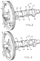
- lift members 40 Such is particularly adaptable to the two cylinders of a V-twin engine.
- the orientation of flat surfaces 48 and 50, and accordingly, lift members 40 could be modified for a different engine configuration. It can thus be appreciated that, as shaft 32 rotates, it engages bulbous portions 52 of lift members 40 at flat surfaces 48 and 50, thereby allowing lift members 40 to disengage the respective exhaust valve tappets.
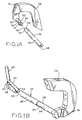
- First segment 34 includes scalloped portion 54 and tongue 56 having a substantially semi-circular cross sectional shape.
- second segment 36 includes tongue 58 which also has a substantially semi-circular cross section as shown in Fig. 1A and in more detail in Fig. 11.
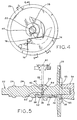
- Tongue 58 includes flat end 60 which abuts against flat portion 62 of first segment 34. In assembled form, the forces holding segments 34 and 36 of shaft 32 together are supplied at the ends of shaft 32. As can be seen in Fig.
- segments 34 and 36 of compression shaft 32 are axially non-interlocking. That is, the mating surfaces of segments 34 and 36 are held together axially by forces exerted on each end of shaft 32, namely, by side surface 68 and bearing surface 65 of camshaft housing 64.
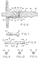
- axially non-interlocking for purposes of this specification means that the connection between segments 34 and 36 need not include fasteners, welding, epoxy or the like. Instead, if the force provided by either side surface 68 or camshaft housing 64 were removed, compression release shaft 32 would be free to separate axially into segments 34 and 36.
- the corresponding shapes include flat surfaces 70 and 72 and end 60 and flat portion 62.
- the corresponding shapes include flat surfaces 70 and 72 and end 60 and flat portion 62.
- one of ordinary skill in the art would be able to substitute other tongue configurations, tongue and groove configurations, etc. which interfit with one another.
- valve actuation device such as valve tappets 28 such that exhaust valves 80 are open, thereby allowing the gases to escape from the cylinder, which in turn results in the starter cord providing less resistance to being pulled.
- valve actuation devices in the illustrated embodiment are shown as valve tappets 28, it is to be understood that the principles embodied by the present invention can be applied to engage other valve actuation devices, depending upon the type of engine in which the present invention is employed.
- Other valve actuation devices include push rods, rocker arms, valves and the like.
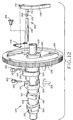
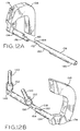
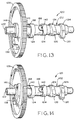
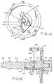
- Figs. 12-22 show a second embodiment of the present invention.
- the embodiments are similar in overall concept and function with the reference numbers for similar elements increased by 100 for the second embodiment, i.e., camshaft 22 in Figs. 1-11 is camshaft 122 in Figs. 12-22.
- Major differences between the second embodiment and the discussion above involve the spring, the location of one of the flat surfaces on the compression release shaft, and the size of the bulbous portion of the lift member.
- torsional spring 144 is attached to cam gear 126 with rivet 186, whereas in the first embodiment that end of torsional spring 44 is inserted in hole 74 of cam gear 26.
- the end of spring 144 has a loop that goes around pressed in rivet 186.
Landscapes
- Engineering & Computer Science (AREA)
- Mechanical Engineering (AREA)
- General Engineering & Computer Science (AREA)
- Valve Device For Special Equipments (AREA)
Claims (9)
- Mécanisme de décompression (20) pour assurer une décompression lors du démarrage d'un moteur à combustion interne à plusieurs cylindres comprenant un arbre à cames (22) sur lequel sont disposés des cames (24) et un pignon de commande de distribution (26), l'arbre à cames étant monté mobile en rotation dans un logement (64), ledit mécanisme comprenant :caractérisé en ce que ledit élément formant masselotte (38) est retenu entre le pignon de commande de distribution (26) et le logement (64), le logement définissant une surface d'appui pour ledit élément formant masselotte.au moins deux éléments de levage (40) montés pour effectuer un mouvement de va-et-vient dans l'arbre à cames, lesdits éléments de levage étant adaptés pour venir en contact avec des dispositifs d'actionnement de soupape (28) ;un arbre de décompression (32) relié à un élément formant masselotte (38), ledit arbre de décompression (32) s'étendant à travers le pignon de commande de distribution et se prolongeant dans un alésage de l'arbre à cames (22), ledit arbre de décompression venant en prise avec les deux éléments de levage (40) ;
- Mécanisme de décompression selon la revendication 1, caractérisé en ce que ledit arbre de décompression (32) comprend des premier et second segments d'arbre de décompression (34, 36) disposés bout à bout.
- Mécanisme de décompression (20) selon la revendication 2, caractérisé en ce que lesdits premier et second segments d'arbre de décompression (34, 36) sont indépendants l'un de l'autre axialement et interdépendants en rotation.
- Mécanisme de décompression (20) selon la revendication 3, caractérisé en ce que :chacun desdits premier et second segments (34, 36) comprend une partie saillante (56, 58) s'étendant à partir de lui ; etlesdites parties saillantes (56, 58) présentent des formes complémentaires qui s'accouplent l'une avec l'autre.
- Mécanisme de décompression (20) selon l'une quelconque des revendications précédentes, caractérisé en ce que ledit premier segment d'arbre de décompression (34) est formé solidairement dudit élément formant masselotte (38).
- Mécanisme de décompression (20) selon la revendication 5, caractérisé en ce que ledit élément formant masselotte (38) est réalisé à partir d'une poudre métallique.
- Mécanisme de décompression selon l'une quelconque des revendications précédentes, caractérisé en ce que l'un desdits premier et second segments (34, 36) est réalisé à partir d'une poudre métallique.
- Mécanisme de décompression (20) selon l'une quelconque des revendications 2 à 7, caractérisé en ce que :ledit premier segment d'arbre de décompression (34) s'étend à travers le pignon de commande de distribution (26) et est formé solidairement dudit élément formant masselotte (38) ; etune extrémité dudit second segment d'arbre de décompression (36) vient en butée contre l'une des cames (24) ;la paroi du logement (64) et la came (24) définissant ainsi des surfaces d'appui (65, 68) qui maintiennent ensemble lesdits premier et second segments (34, 36).
- Mécanisme de décompression (20) selon la revendication 1, caractérisé en ce qu'une extrémité dudit arbre de décompression (32) vient en butée contre l'une des cames (24) en s'appuyant sur elle, les surfaces d'appui (65, 68) du logement (64) et de la came (24) retenant ainsi axialement ledit élément formant masselotte (38) et ledit arbre de décompression (32).
Applications Claiming Priority (2)
| Application Number | Priority Date | Filing Date | Title |
|---|---|---|---|
| US358012 | 1999-07-21 | ||
| US09/358,012 US6269786B1 (en) | 1999-07-21 | 1999-07-21 | Compression release mechanism |
Publications (3)
| Publication Number | Publication Date |
|---|---|
| EP1070833A2 EP1070833A2 (fr) | 2001-01-24 |
| EP1070833A3 EP1070833A3 (fr) | 2001-06-13 |
| EP1070833B1 true EP1070833B1 (fr) | 2004-08-18 |
Family
ID=23407938
Family Applications (1)
| Application Number | Title | Priority Date | Filing Date |
|---|---|---|---|
| EP20000112758 Expired - Lifetime EP1070833B1 (fr) | 1999-07-21 | 2000-06-16 | Mécanisme de décompression |
Country Status (5)
| Country | Link |
|---|---|
| US (1) | US6269786B1 (fr) |
| EP (1) | EP1070833B1 (fr) |
| AU (1) | AU740295B2 (fr) |
| CA (1) | CA2312498C (fr) |
| DE (1) | DE60013048T2 (fr) |
Cited By (1)
| Publication number | Priority date | Publication date | Assignee | Title |
|---|---|---|---|---|
| DE102008020909A1 (de) | 2008-04-17 | 2009-10-29 | Weber Technology Ag | Dekompressionsvorrichtung für eine Brennkraftmaschine |
Families Citing this family (25)
| Publication number | Priority date | Publication date | Assignee | Title |
|---|---|---|---|---|
| JP3705726B2 (ja) * | 1999-12-15 | 2005-10-12 | 川崎重工業株式会社 | 自動デコンプ装置 |
| US6886518B2 (en) * | 2000-02-18 | 2005-05-03 | Briggs & Stratton Corporation | Retainer for release member |
| JP2002303110A (ja) * | 2001-04-05 | 2002-10-18 | Yamaha Motor Co Ltd | エンジンのデコンプ装置 |
| US6874458B2 (en) | 2001-12-28 | 2005-04-05 | Kohler Co. | Balance system for single cylinder engine |
| JP3973085B2 (ja) * | 2002-03-29 | 2007-09-05 | ヤマハモーターパワープロダクツ株式会社 | エンジンのデコンプ装置 |
| US6739304B2 (en) | 2002-06-28 | 2004-05-25 | Kohler Co. | Cross-flow cylinder head |
| US6684846B1 (en) | 2002-07-18 | 2004-02-03 | Kohler Co. | Crankshaft oil circuit |
| US6732701B2 (en) | 2002-07-01 | 2004-05-11 | Kohler Co. | Oil circuit for twin cam internal combustion engine |
| US6837206B2 (en) | 2002-07-11 | 2005-01-04 | Kohler Co. | Crankcase cover with oil passages |
| US6742488B2 (en) | 2002-07-18 | 2004-06-01 | Kohler Co. | Component for governing air flow in and around cylinder head port |
| US6752846B2 (en) * | 2002-07-18 | 2004-06-22 | Kohler Co. | Panel type air filter element with integral baffle |
| US6837207B2 (en) | 2002-07-18 | 2005-01-04 | Kohler Co. | Inverted crankcase with attachments for an internal combustion engine |
| US6672269B1 (en) * | 2002-07-18 | 2004-01-06 | Kohler Co. | Automatic compression release mechanism |
| US6978751B2 (en) | 2002-07-18 | 2005-12-27 | Kohler Co. | Cam follower arm for an internal combustion engine |
| DE10253231B3 (de) * | 2002-11-15 | 2004-02-12 | Dr.Ing.H.C. F. Porsche Ag | Automatische Dekompressionsvorrichtung für ventilgesteuerte Brennkraftmaschinen |
| WO2005019634A2 (fr) * | 2003-08-20 | 2005-03-03 | Kohler Co. | Mecanisme de decompression automatique comprenant une fonction empechant toute desactivation involontaire pendant l'arret du moteur |
| JP2005105972A (ja) * | 2003-09-30 | 2005-04-21 | Fuji Heavy Ind Ltd | エンジンのデコンプ装置 |
| JP4234653B2 (ja) * | 2004-09-03 | 2009-03-04 | ヤマハ発動機株式会社 | エンジンのデコンプ装置 |
| JP4382621B2 (ja) * | 2004-09-29 | 2009-12-16 | 本田技研工業株式会社 | デコンプ装置付きカム機構 |
| JP4490846B2 (ja) * | 2005-02-21 | 2010-06-30 | 本田技研工業株式会社 | エンジンのデコンプ装置 |
| US7506625B2 (en) | 2006-03-31 | 2009-03-24 | Caterpillar Inc. | Method and apparatus for controlling engine valve timing |
| JP4696092B2 (ja) * | 2007-06-08 | 2011-06-08 | 本田技研工業株式会社 | 内燃機関のデコンプ装置 |
| MA31817B1 (fr) * | 2009-04-24 | 2010-11-01 | Nasserlehaq Nsarellah | Arbre a cames coulissantes et intercalaires entre rails a position variable et poussoirs pour la distribution variable continue chez les moteurs a combustion interne de quatre temps. |
| JP6068424B2 (ja) * | 2014-12-08 | 2017-01-25 | 富士重工業株式会社 | デコンプ装置 |
| CN115585029A (zh) * | 2021-06-22 | 2023-01-10 | 李贵臣 | 一种智能控制气门闭合时间的装置 |
Family Cites Families (34)
| Publication number | Priority date | Publication date | Assignee | Title |
|---|---|---|---|---|
| US868765A (en) | 1906-11-19 | 1907-10-22 | Dock Gas Engine Company | Internal-combustion engine. |
| US1439798A (en) | 1921-07-09 | 1922-12-26 | Wright Aeronautical Corp | Compression-relief device for internal-combustion engines |
| US1990427A (en) | 1930-06-05 | 1935-02-05 | Marshall Sons And Company Ltd | Means for starting compressionignition oil engines |
| US2086609A (en) | 1932-10-06 | 1937-07-13 | Packard Motor Car Co | Internal combustion engine |
| US2054928A (en) | 1933-09-11 | 1936-09-22 | Gen Motors Corp | Compression release mechanism |
| FR896700A (fr) | 1942-07-13 | 1945-02-28 | F A M O Fahrzeug Und Motorenwe | Dispositif décompresseur de démarrage pour moteurs à combustion interne |
| GB607750A (en) | 1946-02-11 | 1948-09-03 | Coventry Climax Eng Ltd | Improvements in decompressor mechanism for compression ignition engines |
| US2947300A (en) | 1957-05-31 | 1960-08-02 | Outboard Marine Corp | Starter-controlled engine compression relief |
| US3314408A (en) | 1965-05-17 | 1967-04-18 | Kohler Co | Centrifugally operated compression release mechanism |
| US3362390A (en) | 1966-02-09 | 1968-01-09 | Wisconsin Motor Corp | Automatic compression release |
| US3381676A (en) | 1967-04-12 | 1968-05-07 | Tecumseh Products Co | Compression relief mechanism |
| US3496922A (en) | 1968-04-18 | 1970-02-24 | Tecumseh Products Co | Compression relief mechanism |
| US3511219A (en) | 1968-11-12 | 1970-05-12 | Wisconsin Motors Corp | Automatic compression release |
| US3620203A (en) | 1970-03-11 | 1971-11-16 | Briggs & Stratton Corp | Automatic compression relief mechanism |
| US3897768A (en) | 1973-11-19 | 1975-08-05 | Tecumseh Products Co | Compression relief mechanism |
| JPS6032507U (ja) | 1983-08-10 | 1985-03-05 | 川崎重工業株式会社 | エンジンのオ−トデコンプ装置 |
| US4590905A (en) | 1984-05-04 | 1986-05-27 | Honda Giken Kogyo Kabushiki Kaisha | Process for decompression control in internal combustion engine and apparatus therefor |
| JPS61178011U (fr) * | 1985-04-25 | 1986-11-06 | ||
| US4696266A (en) | 1985-05-14 | 1987-09-29 | Fuji Jukogyo Kabushiki Kaisha | Decompression apparatus for engines |
| JPH0267409A (ja) | 1988-08-31 | 1990-03-07 | Yamaha Motor Co Ltd | エンジンのデコンプ装置 |
| JPH0250107U (fr) * | 1988-10-03 | 1990-04-09 | ||
| US4898133A (en) | 1988-12-07 | 1990-02-06 | Kohler Co. | Automatic compression release apparatus for an internal combustion engine |
| US4892068A (en) | 1989-06-09 | 1990-01-09 | Kohler Co. | Geared automatic compression release for an internal combustion engine |
| JPH03107515A (ja) | 1989-09-20 | 1991-05-07 | Honda Motor Co Ltd | V型エンジン |
| JPH03107514A (ja) | 1989-09-20 | 1991-05-07 | Honda Motor Co Ltd | 内燃機関の始動負荷軽減装置 |
| EP0425899B1 (fr) | 1989-11-02 | 1994-01-26 | Kubota Corporation | Moteur avec régulation mécanique et dispositif de décompression |
| IT1254606B (it) * | 1992-02-10 | 1995-09-28 | Cagiva Motor | Dispositivo automatico di decompressione di un motore di una motocicletta in fase di avviamento |
| US5197422A (en) | 1992-03-19 | 1993-03-30 | Briggs & Stratton Corporation | Compression release mechanism and method for assembling same |
| WO1993025808A1 (fr) | 1992-06-11 | 1993-12-23 | Generac Corporation | Moteur a combustion interne pour groupe d'alimentation portable |
| US5402759A (en) | 1994-07-08 | 1995-04-04 | Outboard Marine Corporation | Cylinder decompression arrangement in cam shaft |
| JPH0949408A (ja) | 1995-08-07 | 1997-02-18 | Sanshin Ind Co Ltd | オートデコンプ装置を備える船外機 |
| JP3107515B2 (ja) | 1996-03-29 | 2000-11-13 | アロン化成株式会社 | ごみ収集車のごみ収集装置 |
| US5809958A (en) | 1997-05-08 | 1998-09-22 | Briggs & Stratton Corporation | Compression release for multi-cylinder engines |
| US5823153A (en) | 1997-05-08 | 1998-10-20 | Briggs & Stratton Corporation | Compressing release with snap-in components |
-
1999
- 1999-07-21 US US09/358,012 patent/US6269786B1/en not_active Expired - Lifetime
-
2000
- 2000-06-16 DE DE60013048T patent/DE60013048T2/de not_active Expired - Fee Related
- 2000-06-16 EP EP20000112758 patent/EP1070833B1/fr not_active Expired - Lifetime
- 2000-06-27 CA CA002312498A patent/CA2312498C/fr not_active Expired - Lifetime
- 2000-07-20 AU AU48734/00A patent/AU740295B2/en not_active Ceased
Cited By (2)
| Publication number | Priority date | Publication date | Assignee | Title |
|---|---|---|---|---|
| DE102008020909A1 (de) | 2008-04-17 | 2009-10-29 | Weber Technology Ag | Dekompressionsvorrichtung für eine Brennkraftmaschine |
| DE102008020909B4 (de) * | 2008-04-17 | 2014-10-09 | Weber Technology Ag | Dekompressionsvorrichtung für eine Brennkraftmaschine |
Also Published As
| Publication number | Publication date |
|---|---|
| DE60013048D1 (de) | 2004-09-23 |
| EP1070833A2 (fr) | 2001-01-24 |
| CA2312498A1 (fr) | 2001-01-21 |
| EP1070833A3 (fr) | 2001-06-13 |
| AU4873400A (en) | 2001-01-25 |
| CA2312498C (fr) | 2007-10-30 |
| AU740295B2 (en) | 2001-11-01 |
| US6269786B1 (en) | 2001-08-07 |
| DE60013048T2 (de) | 2005-09-01 |
Similar Documents
| Publication | Publication Date | Title |
|---|---|---|
| EP1070833B1 (fr) | Mécanisme de décompression | |
| CA2068955C (fr) | Mecanisme de decompression actionne par la force centrifuge | |
| EP1892388B1 (fr) | Moteur avec dispositif de décompression | |
| US4453507A (en) | Centrifugally responsive compression release mechanism | |
| KR960007963B1 (ko) | 내연기관용 밸브제어수단 | |
| US6343581B2 (en) | Variable valve timing and lift structure for four cycle engine | |
| US8033261B1 (en) | Valve actuation system and related methods | |
| US5184586A (en) | Mechanical compression release for an internal combustion engine | |
| JP4103580B2 (ja) | 弁開閉時期制御装置 | |
| EP0834647B1 (fr) | Commande de soupape pour moteur | |
| EP1380729A1 (fr) | Dispositif de décompression pour moteur à combustion interne | |
| US6789521B2 (en) | Valve system for engine | |
| CA2506097C (fr) | Mecanisme de commande de decompression | |
| EP1460240B1 (fr) | Came munie d'un système de décompression | |
| US6314929B1 (en) | Valve timing control device of internal combustion engine | |
| US20020108596A1 (en) | Vacuum release mechanism | |
| EP1101903A1 (fr) | Dispositif mécanique de décompression | |
| US6886518B2 (en) | Retainer for release member | |
| EP1664516B1 (fr) | Mecanisme de decompression automatique comprenant une fonction empechant toute desactivation involontaire pendant l'arret du moteur | |
| EP3061930B1 (fr) | Arbre et poussoir pour décompression | |
| US7249581B2 (en) | System with camshaft and camshaft receptacle | |
| EP0705382A1 (fr) | Systeme a bossage de came en forme de fleche a action variable | |
| EP4365420A1 (fr) | Dispositif de décompression et moteur | |
| JPH10220318A (ja) | 分配型燃料噴射ポンプ及び動力伝達装置 | |
| JPS6221681Y2 (fr) |
Legal Events
| Date | Code | Title | Description |
|---|---|---|---|
| PUAI | Public reference made under article 153(3) epc to a published international application that has entered the european phase |
Free format text: ORIGINAL CODE: 0009012 |
|
| AK | Designated contracting states |
Kind code of ref document: A2 Designated state(s): DE FR GB IT |
|
| AX | Request for extension of the european patent |
Free format text: AL;LT;LV;MK;RO;SI |
|
| PUAL | Search report despatched |
Free format text: ORIGINAL CODE: 0009013 |
|
| AK | Designated contracting states |
Kind code of ref document: A3 Designated state(s): AT BE CH CY DE DK ES FI FR GB GR IE IT LI LU MC NL PT SE |
|
| AX | Request for extension of the european patent |
Free format text: AL;LT;LV;MK;RO;SI |
|
| 17P | Request for examination filed |
Effective date: 20011201 |
|
| AKX | Designation fees paid |
Free format text: DE FR GB IT |
|
| GRAP | Despatch of communication of intention to grant a patent |
Free format text: ORIGINAL CODE: EPIDOSNIGR1 |
|
| GRAS | Grant fee paid |
Free format text: ORIGINAL CODE: EPIDOSNIGR3 |
|
| GRAA | (expected) grant |
Free format text: ORIGINAL CODE: 0009210 |
|
| AK | Designated contracting states |
Kind code of ref document: B1 Designated state(s): DE FR GB IT |
|
| REG | Reference to a national code |
Ref country code: GB Ref legal event code: FG4D |
|
| REF | Corresponds to: |
Ref document number: 60013048 Country of ref document: DE Date of ref document: 20040923 Kind code of ref document: P |
|
| RIN2 | Information on inventor provided after grant (corrected) |
Inventor name: STERR, RANDALL E. Inventor name: SNYDER, DALE D. Inventor name: KOEHLER, SCOT A. Inventor name: MILLER, WILLIAM M. |
|
| PLBE | No opposition filed within time limit |
Free format text: ORIGINAL CODE: 0009261 |
|
| STAA | Information on the status of an ep patent application or granted ep patent |
Free format text: STATUS: NO OPPOSITION FILED WITHIN TIME LIMIT |
|
| ET | Fr: translation filed | ||
| 26N | No opposition filed |
Effective date: 20050519 |
|
| PGFP | Annual fee paid to national office [announced via postgrant information from national office to epo] |
Ref country code: IT Payment date: 20090526 Year of fee payment: 10 Ref country code: FR Payment date: 20090601 Year of fee payment: 10 |
|
| PGFP | Annual fee paid to national office [announced via postgrant information from national office to epo] |
Ref country code: GB Payment date: 20090518 Year of fee payment: 10 Ref country code: DE Payment date: 20090601 Year of fee payment: 10 |
|
| GBPC | Gb: european patent ceased through non-payment of renewal fee |
Effective date: 20100616 |
|
| REG | Reference to a national code |
Ref country code: FR Ref legal event code: ST Effective date: 20110228 |
|
| PG25 | Lapsed in a contracting state [announced via postgrant information from national office to epo] |
Ref country code: IT Free format text: LAPSE BECAUSE OF NON-PAYMENT OF DUE FEES Effective date: 20100616 |
|
| PG25 | Lapsed in a contracting state [announced via postgrant information from national office to epo] |
Ref country code: DE Free format text: LAPSE BECAUSE OF NON-PAYMENT OF DUE FEES Effective date: 20110101 |
|
| PG25 | Lapsed in a contracting state [announced via postgrant information from national office to epo] |
Ref country code: FR Free format text: LAPSE BECAUSE OF NON-PAYMENT OF DUE FEES Effective date: 20100630 |
|
| PG25 | Lapsed in a contracting state [announced via postgrant information from national office to epo] |
Ref country code: GB Free format text: LAPSE BECAUSE OF NON-PAYMENT OF DUE FEES Effective date: 20100616 |