EP1070862B1 - Senkrechter Karabinerhaken mit breiter Unterstützungsfläche - Google Patents
Senkrechter Karabinerhaken mit breiter Unterstützungsfläche Download PDFInfo
- Publication number
- EP1070862B1 EP1070862B1 EP00104598A EP00104598A EP1070862B1 EP 1070862 B1 EP1070862 B1 EP 1070862B1 EP 00104598 A EP00104598 A EP 00104598A EP 00104598 A EP00104598 A EP 00104598A EP 1070862 B1 EP1070862 B1 EP 1070862B1
- Authority
- EP
- European Patent Office
- Prior art keywords
- karabiner
- arcuate portion
- pin
- support
- arcuate
- Prior art date
- Legal status (The legal status is an assumption and is not a legal conclusion. Google has not performed a legal analysis and makes no representation as to the accuracy of the status listed.)
- Expired - Lifetime
Links
Images



Classifications
-
- F—MECHANICAL ENGINEERING; LIGHTING; HEATING; WEAPONS; BLASTING
- F16—ENGINEERING ELEMENTS AND UNITS; GENERAL MEASURES FOR PRODUCING AND MAINTAINING EFFECTIVE FUNCTIONING OF MACHINES OR INSTALLATIONS; THERMAL INSULATION IN GENERAL
- F16B—DEVICES FOR FASTENING OR SECURING CONSTRUCTIONAL ELEMENTS OR MACHINE PARTS TOGETHER, e.g. NAILS, BOLTS, CIRCLIPS, CLAMPS, CLIPS OR WEDGES; JOINTS OR JOINTING
- F16B45/00—Hooks; Eyes
- F16B45/02—Hooks with pivoting or elastically bending closing member
- F16B45/036—Hooks with pivoting or elastically bending closing member with an elastically bending closing member
Definitions
- the present invention relates to auxiliary equipment used for personal safety and, in particular, for sports climbing.
- the invention relates to a quick-locking safety karabiner comprising a shaped body having an arcuate striker portion which defines a hollow conformation by which the karabiner can be attached to an elongated support element such as a rope or a loop element, the hollow attachment conformation being accessible via an opening in the body adjacent the arcuate part and in correspondence to which there is disposed a closing element which can oscillate in the general plane of the arcuate portion between a position intercepting the opening in which it engages with the arcuate portion and an open position in which it is spaced from the arcuate portion.
- Karabiners of the type defined above known at present have the main drawback of being substantially flat, so that, when they are connected by means of a rope or a tape to a fixture on a wall, e.g. ringed piton, they lie parallel to the wall because of their shape and the force of gravity.
- Another characteristic of the karabiner known at present is that the force generated by the spring which regulates the opening of the mobile part lies in a plane without constrains so that a climber who wants to insert his safety rope into one of these karabiners must use one hand to hold the karabiner away from the wall and hold it immobile until the rope is inserted into it by means of the other hand which must in some way press the rope onto the mobile part in order to rotate it to free the access for the rope.
- FR-A-331.831 and FR-E-2.734 disclose a karabiner comprising a shaped body having an arcuate striker portion defining a hook extremity for the attachment of an elongated support element - such as a rope - in which the shaped body has an opening adjacent the arcuate portion corresponding to which is disposed a closing element.
- the closing element can oscillate in the general plane defined by the arcuate portion between one position of intercepting the opening, in which it engages with the arcuate portion, and an open position, in which it is spaced from the said portion.
- the shaped body defines a base of support, substantially flat and transverse to the general plane of the arcuate portion. The said base of support lies entirely onto a single plane, thus providing a "surface to surface" bearing of the karabiner on external surfaces.
- the object of the present invention is a karabiner of the type described above, in which the body defines a base that, in turn, defines unambiguously at least one plane of support transversal to the general plane of the arcuate portion, so that in normal use the karabiner lies naturally with the arcuate portion perpendicular to the surface on which it lies.
- the object of the present invention is therefore a karabiner of the type disclosed in FR-A-331.831 or in FR-E-2.734, as described in the preamble of claim 1, characterised in that, when the karabiner lies with its base of support on a surface, said base of support rests on said surface by means of three or more points of support, so that the arcuate portion extends perpendicularly to such a surface.
- the karabiner automatically lies in such a way the force of the spring regulating the mobile part is opposed by the reaction of the surface of support.
- the rope may thus be inserted into its hollow conformation of attachment by one hand alone - i.e. by the hand that controls the rope - simply by pressing the rope onto the mobile part.
- the said part being attached by a hinge whose constraining reactions are balanced by the surface of support on which it lies, must move in the only degree of freedom left to it and frees enough space for the rope to enter the karabiner. This operation can be done quickly and in relative safety.
- the closing element has a vertex part which can engage a hook extremity of the arcuate part and presents a tapered form, decreasing in width from its hinged base to its vertex.
- a safety karabiner which can be used in particular in climbing, is indicated in general by reference number 1. It comprises a shaped body 3 preferably produced from a single piece of light alloy, preferably high-strength aluminum such as Ergal or Avional, having an arcuate striker portion 5 which surrounds at least part of a hollow attachment conformation 5a.
- This attachment conformation 5a is shaped as a saddle to receive an elongated support element such as a rope C or loop element of the user e.g. a climber.
- a forked portion which includes a pair of arms 9 arranged substantially in a U-shape.
- the arms 9 comprise corresponding circular seats in the extremities opposite the arcuate portion 5. The function of these seats will be made clear below.
- the arms 9 define a plane substantially perpendicular to the plane in which the arcuate portion 5 lies, and so define a support plane for the karabiner 1, e.g. on the surface of a rockface.
- the support base of the karabiner 1 is transverse to the general plane in which the arcuate portion 5 lies, so in the position where the karabiner 1 lies stable with its base on a surface, the arcuate portion 5 extends perpendicular to that surface.
- the element 15 is fitted in order to oscillate in the general plane of the arcuate portion 5 between a first position in which it intercepts the opening of the karabiner 1 and where a vertex part of the element 15 engages a hook portion of the arcuate portion 5, and an open position in which the vertex part is spaced from the hook element.
- the element 15 presents a generally tapered shape, which could be produced by metal wire e.g. steel piano wire, shaped to a V- or U-shape.
- the two arms of the element 15 separate slightly from the vertex part to finish up approximately perpendicular to holes 17.
- the closing part consists of an element substantially parallel to the plane of opening; in such circumstances the rope wound about it tends to open the karabiner and facilitate the escape of the rope from the karabiner.
- the closing element 15 in the karabiner 1 presents a shape tapered toward its vertex, in similar circumstances the rope C which tends to wind around the closing element is forced to slide along the tapered shape to fall into the saddle-backed conformation 5a; there is a natural tendency for the rope to return to the saddle-backed conformation 5a without imposing such force on the closing element 15 as to cause it to open.
- the closing element 15 remains therefore in its closed configuration and guarantees reliable operation of the karabiner 1.
- the closing element 15 is slightly asymmetrical in that the arms are of different lengths in such a way as that one of the transverse projections engages one of the holes 17, while the other engages the other of the holes 17, the holes 17 being parallel but staggered so that there is an elastic force returning the closing element 15 to its position of intercepting the opening of the karabiner 1.
- the closing element 15 is wound around the pin 2 and engages the holes 17 symmetrically.
- the circular seats of the extremities of the arms 9 are each surrounded by their respective collars and are engaged by the transverse pin 2 which is of a corresponding shape.
- the pin 2 acts as the anchor for connecting the karabiner 1 with a retaining element 6, e.g. consisting of a flexible tape or ribbon with hooks at opposite extremities, one of which surrounds the pin 2 while the other is engaged in an auxiliary karabiner M, e.g. of conventional structure, inserted into a ring piton inserted into a rockface.
- the pin 2 is produced from a solid or hollow cylinder and is connected in a stable way to the arms 9 either by having screw-threads and action seats or by having seats with different diameters and one or two external lock screws.
- each collar is sufficiently broad radially so that, when the pin 2 is surrounded by the retaining element 6, there is space between the outside surface of the element 6 and the outer peripheral surface of the collar itself.
- the element 6 is raised with regard to the surface (i.e. not in contact with the surface) and so avoids the kind of chafing that might damage it.
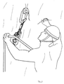
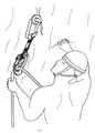
- Figs 3 and 4 show a climber who is carrying out the operation of hooking the line C to the karabiner 1.
- the operation of hooking the rope C can be carried out alone by the hand which holds the rope C and without intervening directly with the opening of the karabiner 1, since the arcuate portion 5 of the karabiner 1 is always disposed perpendicularly to the surface of the rockface due to the support base of at least three points defined by the arcuate portion 5 and the forked portion.
- the climber can insert the rope C into the karabiner from left to right or from right to left, or whatever side he pleases without worrying about avoiding certain passes of the rope C from one side or the other of the karabiner 1.
- the safety karabiner illustrated has been described for use in a rock climbing context, but it can be used for various other uses, e.g. for workers working on site, or in any situation where the characteristics of the invention afford an advantage.
Landscapes
- Engineering & Computer Science (AREA)
- General Engineering & Computer Science (AREA)
- Mechanical Engineering (AREA)
- Emergency Lowering Means (AREA)
- Hooks, Suction Cups, And Attachment By Adhesive Means (AREA)
- Supports Or Holders For Household Use (AREA)
Claims (10)
- Schnellverschluß-Sicherheitskarabiner, umfassend einen geformten Grundkörper (3) zum Befestigen eines länglichen Halteelements, wie z.B. einem Seil oder einem Schlaufenelement, wobei der Grundkörper (3) eine Öffnung nächst dem bogenförmigen Abschnitt (5) aufweist, passend zu welchem ein Verschlußelement (15) angeordnet ist, das in der allgemeinen Ebene des bogenförmigen Abschnitts (5) zwischen einer Halteposition, in der es mit dem bogenförmigen Abschnitt (5) zusammenwirkt, und einer offenen Position, in der es von dem genannten Abschnitt (5) beabstandet ist, hin- und herschwenken kann, wobei der Grundkörper (3) eine stabile Auflagebasis definiert, die im wesentlichen flach ist und quer zur allgemeinen Ebene des bogenförmigen Abschnitts (5) liegt, dadurch gekennzeichnet, dass der Karabiner (1) mit seiner Auflagebasis auf einer Oberfläche liegt, wobei die genannte Auflagebasis mittels drei oder mehr Auflagepunkten auf der genannten Fläche ruht, so daß der bogenförmige Abschnitt (5) sich senkrecht zu einer solchen Fläche erstreckt.
- Karabiner nach Anspruch 1, dadurch gekennzeichnet, dass der Grundkörper (3) einen gabelförmigen Abschnitt umfaßt, der dem bogenförmigen Abschnitt (5) gegenüberliegt, und dass der Karabiner zwei ein Paar bildende auseinanderlaufende Schenkel (9) aufweist, an denen das Verschlußelement (15), der bogenförmige Abschnitt (5) und der gabelförmige Abschnitt gelenkig befestigt sind, und die die drei oder mehr genannten Auflagepunkte bilden.
- Karabiner nach Anspruch 2, dadurch gekennzeichnet, dass der genannte Grundkörper (3) durch plastisches Umformen einer leichten Aluminiumlegierung mit hoher Festigkeit, insbesondere z.B. aus Ergal® oder Avional®, oder einem hochfesten Stahl hergestellt ist, indem aufeinanderfolgende Bearbeitungen durchgeführt werden, um das Hakenende senkrecht zu dem gabelförmigen Abschnitt herzustellen.
- Karabiner nach Anspruch 2 oder 3, dadurch gekennzeichnet, dass das Verschlußelement (15) mit einem Scheitelabschnitt versehen ist, um mit dem genannten Hakenende des bogenförmigen Abschnitts (5) zusammenzuwirken und dass sich das Verschlußelement (15) im allgemeinen von seinem gelenkig befestigten Abschnitt zum Scheitelabschnitt hin verjüngt.
- Karabiner nach Anspruch 4, dadurch gekennzeichnet, dass das Verschlußelement (15) durch Mittel realisiert ist, die aus einem im wesentlichen V- oder U-förmigen Stahldraht bestehen, dessen Schenkel jeweilige Quervorsprünge aufweisen, die mit dem Gelenkverbindungspunkt korrespondieren, um in korrespondierende Löcher (17) einzugreifen, die in Vorsprüngen (13) vorgesehen sind, die sich von den freien Enden der genannten auseinanderlaufenden Schenkel (9) erstrecken.
- Karabiner nach Anspruch 5, dadurch gekennzeichnet, dass die genannten Löcher (17), die in verschiedenen Schenkeln des gabelförmigen Abschnitts liegen, parallele, jedoch versetzte Achsen haben.
- Karabiner nach einem der Ansprüche 2 bis 6, dadurch gekennzeichnet, dass der genannte Karabiner einen Querbolzen (2) einschließt, der geeignet ist, mit einem länglichen Halteelement (6), wie z.B. einem Seil oder einem Schlaufenelement verbunden zu werden, welches den Bolzen umgibt, wobei der Bolzen (2) in ein Paar von korrespondierenden kreisförmigen Aufnahmen eingreift, die jeweils in einem entsprechenden Schenkel (9) nahe dem freien Ende gegenüber dem bogenförmigen Abschnitt (5) vorgesehen sind, und wobei der genannte Bolzen (2) in Ebenen liegt, die annähernd parallel zu dem genannten bogenförmigen Abschnitt (5) sind.
- Karabiner nach Anspruch 7, dadurch gekennzeichnet, dass der Bolzen (2) derart angeordnet ist, dass das genannte längliche Halteelement (6), das den Bolzen (2) umgibt, gegenüber der Auflagebasis mit dem Ziel angehoben wird, zu verhindern, dass eine Fläche, auf der der Karabiner (1) mit seiner Auflagebasis ruht, an dem Halteelement (6) entlangscheuert.
- Karabiner nach Anspruch 7 oder 8, dadurch gekennzeichnet, dass der genannte Bolzen (2) ein annähernd zylindrisches Element ist, das auf ähnliche Art wie der Grundkörper (3) aus einer leichten Aluminiumlegierung mit hoher Festigkeit, insbesondere z.B. aus Ergal® odel Avional®, oder einem hochfesten Stahl hergestellt ist, und dass er in den Aufnahmen durch Schraubgewinde oder Befestigungselemente verankert werden kann.
- Karabiner nach den Ansprüche 7 bis 9, dadurch gekennzeichnet, dass der Bolzen (2) durch Walzen oder Drehen einer vorgefertigten Stange, z.B. einer gezogenen Stange, hergestellt ist.
Applications Claiming Priority (2)
| Application Number | Priority Date | Filing Date | Title |
|---|---|---|---|
| ITTO990649 | 1999-07-21 | ||
| IT1999TO000649A IT1310133B1 (it) | 1999-07-21 | 1999-07-21 | Dispositivo di sicurezza ad aggancio rapido a moschettone con based'appoggio allargata e gancio ortogonale |
Publications (2)
| Publication Number | Publication Date |
|---|---|
| EP1070862A1 EP1070862A1 (de) | 2001-01-24 |
| EP1070862B1 true EP1070862B1 (de) | 2003-07-23 |
Family
ID=11417990
Family Applications (1)
| Application Number | Title | Priority Date | Filing Date |
|---|---|---|---|
| EP00104598A Expired - Lifetime EP1070862B1 (de) | 1999-07-21 | 2000-03-15 | Senkrechter Karabinerhaken mit breiter Unterstützungsfläche |
Country Status (5)
| Country | Link |
|---|---|
| EP (1) | EP1070862B1 (de) |
| AT (1) | ATE245776T1 (de) |
| DE (1) | DE60003983T2 (de) |
| ES (1) | ES2204375T3 (de) |
| IT (1) | IT1310133B1 (de) |
Families Citing this family (5)
| Publication number | Priority date | Publication date | Assignee | Title |
|---|---|---|---|---|
| GB0019136D0 (en) * | 2000-08-04 | 2000-09-27 | Dmm Eng Ltd | Karabiners |
| GB2441142A (en) * | 2006-08-25 | 2008-02-27 | Christopher John Dale | Carabiner with first and second hook sections |
| AT11210U1 (de) * | 2008-11-27 | 2010-06-15 | Aba Hoertnagl Kg Werkzeuge Vor | Karabinerhaken |
| BR112016011806A2 (pt) | 2013-11-26 | 2017-08-08 | Basf Se | Estruturante para fraturar hidraulicamente uma formação subterrânea, e, método para formar um estruturante |
| GB2541457A (en) * | 2015-08-21 | 2017-02-22 | Latchways Plc | A karabiner |
Family Cites Families (3)
| Publication number | Priority date | Publication date | Assignee | Title |
|---|---|---|---|---|
| FR2734E (fr) * | 1904-11-15 | Gabriel Jules Robergel | Perfectionnements aux crochets-mousquetons | |
| FR2531870B1 (fr) * | 1982-08-18 | 1985-06-28 | Contat Freres Ets | Mousqueton, notamment pour l'alpinisme, et son procede de fabrication |
| US5913479A (en) * | 1996-09-18 | 1999-06-22 | Westwood, Iii; Samuel M. | Snap hook with pivotal gate |
-
1999
- 1999-07-21 IT IT1999TO000649A patent/IT1310133B1/it active
-
2000
- 2000-03-15 AT AT00104598T patent/ATE245776T1/de not_active IP Right Cessation
- 2000-03-15 DE DE60003983T patent/DE60003983T2/de not_active Expired - Fee Related
- 2000-03-15 EP EP00104598A patent/EP1070862B1/de not_active Expired - Lifetime
- 2000-03-15 ES ES00104598T patent/ES2204375T3/es not_active Expired - Lifetime
Also Published As
| Publication number | Publication date |
|---|---|
| DE60003983T2 (de) | 2004-03-04 |
| DE60003983D1 (de) | 2003-08-28 |
| ES2204375T3 (es) | 2004-05-01 |
| IT1310133B1 (it) | 2002-02-11 |
| EP1070862A1 (de) | 2001-01-24 |
| ITTO990649A1 (it) | 2001-01-21 |
| ATE245776T1 (de) | 2003-08-15 |
Similar Documents
| Publication | Publication Date | Title |
|---|---|---|
| US9168402B2 (en) | Rope grab | |
| US9636528B2 (en) | Rope grab | |
| US6959783B2 (en) | Figure eight descender | |
| CA1222981A (en) | Descender | |
| AU722413B2 (en) | Guarded snap hook | |
| US5265696A (en) | Ladder climbing safety clamp | |
| US5005266A (en) | Self-closing carabiner | |
| CN109603020B (zh) | 用于纺织绳索的下降器装置 | |
| US6102264A (en) | Tool holder for a tool belt | |
| US12257463B1 (en) | Bucket hook with tether hole | |
| CA2514268C (en) | Safety hook for patient lift | |
| US20110113604A1 (en) | Easy clip carabiner with a retractable trigger | |
| WO1997023406A1 (en) | A lifting hook | |
| EP1666104A1 (de) | Vorrichtung zum anhängen und arretieren von kletterseilen | |
| EP1070862B1 (de) | Senkrechter Karabinerhaken mit breiter Unterstützungsfläche | |
| KR20250003909A (ko) | 각형 게이트 카라비너 | |
| EP0527927A1 (de) | Haken. | |
| US7082647B2 (en) | Snap-hook for carrying accessories | |
| EP3001047B1 (de) | Karabiner | |
| CN115957456B (zh) | 一种能适应钩挂吊杆粗细的可调式防坠装置 | |
| RU2828930C1 (ru) | Самоблокирующееся спусковое устройство для двух веревок | |
| RU2015709C1 (ru) | Страховочный карабин | |
| JPH0813968A (ja) | 吊下げ具 | |
| CA1116376A (en) | Anti-fouling latched sling hook | |
| JPH08280829A (ja) | 墜落防止装置のフック |
Legal Events
| Date | Code | Title | Description |
|---|---|---|---|
| PUAI | Public reference made under article 153(3) epc to a published international application that has entered the european phase |
Free format text: ORIGINAL CODE: 0009012 |
|
| AK | Designated contracting states |
Kind code of ref document: A1 Designated state(s): AT BE CH CY DE DK ES FI FR GB GR IE IT LI LU MC NL PT SE |
|
| AX | Request for extension of the european patent |
Free format text: AL;LT;LV;MK;RO;SI |
|
| 17P | Request for examination filed |
Effective date: 20010716 |
|
| AKX | Designation fees paid |
Free format text: AT BE CH CY DE DK ES FI FR GB GR IE IT LI LU MC NL PT SE |
|
| 17Q | First examination report despatched |
Effective date: 20011212 |
|
| GRAH | Despatch of communication of intention to grant a patent |
Free format text: ORIGINAL CODE: EPIDOS IGRA |
|
| GRAH | Despatch of communication of intention to grant a patent |
Free format text: ORIGINAL CODE: EPIDOS IGRA |
|
| GRAA | (expected) grant |
Free format text: ORIGINAL CODE: 0009210 |
|
| AK | Designated contracting states |
Designated state(s): AT BE CH CY DE DK ES FI FR GB GR IE IT LI LU MC NL PT SE |
|
| PG25 | Lapsed in a contracting state [announced via postgrant information from national office to epo] |
Ref country code: NL Free format text: LAPSE BECAUSE OF FAILURE TO SUBMIT A TRANSLATION OF THE DESCRIPTION OR TO PAY THE FEE WITHIN THE PRESCRIBED TIME-LIMIT Effective date: 20030723 Ref country code: IT Free format text: LAPSE BECAUSE OF FAILURE TO SUBMIT A TRANSLATION OF THE DESCRIPTION OR TO PAY THE FEE WITHIN THE PRE;WARNING: LAPSES OF ITALIAN PATENTS WITH EFFECTIVE DATE BEFORE 2007 MAY HAVE OCCURRED AT ANY TIME BEFORE 2007. THE CORRECT EFFECTIVE DATE MAY BE DIFFERENT FROM THE ONE RECORDED.SCRIBED TIME-LIMIT Effective date: 20030723 Ref country code: FI Free format text: LAPSE BECAUSE OF FAILURE TO SUBMIT A TRANSLATION OF THE DESCRIPTION OR TO PAY THE FEE WITHIN THE PRESCRIBED TIME-LIMIT Effective date: 20030723 Ref country code: CY Free format text: LAPSE BECAUSE OF FAILURE TO SUBMIT A TRANSLATION OF THE DESCRIPTION OR TO PAY THE FEE WITHIN THE PRESCRIBED TIME-LIMIT Effective date: 20030723 Ref country code: BE Free format text: LAPSE BECAUSE OF FAILURE TO SUBMIT A TRANSLATION OF THE DESCRIPTION OR TO PAY THE FEE WITHIN THE PRESCRIBED TIME-LIMIT Effective date: 20030723 |
|
| REG | Reference to a national code |
Ref country code: GB Ref legal event code: FG4D |
|
| REG | Reference to a national code |
Ref country code: CH Ref legal event code: EP |
|
| REG | Reference to a national code |
Ref country code: IE Ref legal event code: FG4D |
|
| REF | Corresponds to: |
Ref document number: 60003983 Country of ref document: DE Date of ref document: 20030828 Kind code of ref document: P |
|
| PG25 | Lapsed in a contracting state [announced via postgrant information from national office to epo] |
Ref country code: SE Free format text: LAPSE BECAUSE OF FAILURE TO SUBMIT A TRANSLATION OF THE DESCRIPTION OR TO PAY THE FEE WITHIN THE PRESCRIBED TIME-LIMIT Effective date: 20031023 Ref country code: GR Free format text: LAPSE BECAUSE OF FAILURE TO SUBMIT A TRANSLATION OF THE DESCRIPTION OR TO PAY THE FEE WITHIN THE PRESCRIBED TIME-LIMIT Effective date: 20031023 Ref country code: DK Free format text: LAPSE BECAUSE OF FAILURE TO SUBMIT A TRANSLATION OF THE DESCRIPTION OR TO PAY THE FEE WITHIN THE PRESCRIBED TIME-LIMIT Effective date: 20031023 |
|
| NLV1 | Nl: lapsed or annulled due to failure to fulfill the requirements of art. 29p and 29m of the patents act | ||
| PG25 | Lapsed in a contracting state [announced via postgrant information from national office to epo] |
Ref country code: PT Free format text: LAPSE BECAUSE OF FAILURE TO SUBMIT A TRANSLATION OF THE DESCRIPTION OR TO PAY THE FEE WITHIN THE PRESCRIBED TIME-LIMIT Effective date: 20031223 |
|
| PG25 | Lapsed in a contracting state [announced via postgrant information from national office to epo] |
Ref country code: LU Free format text: LAPSE BECAUSE OF NON-PAYMENT OF DUE FEES Effective date: 20040315 Ref country code: IE Free format text: LAPSE BECAUSE OF NON-PAYMENT OF DUE FEES Effective date: 20040315 Ref country code: GB Free format text: LAPSE BECAUSE OF NON-PAYMENT OF DUE FEES Effective date: 20040315 Ref country code: AT Free format text: LAPSE BECAUSE OF NON-PAYMENT OF DUE FEES Effective date: 20040315 |
|
| PG25 | Lapsed in a contracting state [announced via postgrant information from national office to epo] |
Ref country code: ES Free format text: LAPSE BECAUSE OF NON-PAYMENT OF DUE FEES Effective date: 20040316 |
|
| PGFP | Annual fee paid to national office [announced via postgrant information from national office to epo] |
Ref country code: DE Payment date: 20040319 Year of fee payment: 5 |
|
| PGFP | Annual fee paid to national office [announced via postgrant information from national office to epo] |
Ref country code: FR Payment date: 20040330 Year of fee payment: 5 |
|
| PG25 | Lapsed in a contracting state [announced via postgrant information from national office to epo] |
Ref country code: MC Free format text: LAPSE BECAUSE OF NON-PAYMENT OF DUE FEES Effective date: 20040331 Ref country code: LI Free format text: LAPSE BECAUSE OF NON-PAYMENT OF DUE FEES Effective date: 20040331 Ref country code: CH Free format text: LAPSE BECAUSE OF NON-PAYMENT OF DUE FEES Effective date: 20040331 |
|
| REG | Reference to a national code |
Ref country code: ES Ref legal event code: FG2A Ref document number: 2204375 Country of ref document: ES Kind code of ref document: T3 |
|
| ET | Fr: translation filed | ||
| PLBE | No opposition filed within time limit |
Free format text: ORIGINAL CODE: 0009261 |
|
| STAA | Information on the status of an ep patent application or granted ep patent |
Free format text: STATUS: NO OPPOSITION FILED WITHIN TIME LIMIT |
|
| 26N | No opposition filed |
Effective date: 20040426 |
|
| GBPC | Gb: european patent ceased through non-payment of renewal fee |
Effective date: 20040315 |
|
| REG | Reference to a national code |
Ref country code: CH Ref legal event code: PL |
|
| REG | Reference to a national code |
Ref country code: IE Ref legal event code: MM4A |
|
| REG | Reference to a national code |
Ref country code: ES Ref legal event code: FD2A Effective date: 20040316 |
|
| PG25 | Lapsed in a contracting state [announced via postgrant information from national office to epo] |
Ref country code: DE Free format text: LAPSE BECAUSE OF NON-PAYMENT OF DUE FEES Effective date: 20051001 |
|
| PG25 | Lapsed in a contracting state [announced via postgrant information from national office to epo] |
Ref country code: FR Free format text: LAPSE BECAUSE OF NON-PAYMENT OF DUE FEES Effective date: 20051130 |
|
| REG | Reference to a national code |
Ref country code: FR Ref legal event code: ST Effective date: 20051130 |