EP1070911A2 - Projecteur pour véhicules automobiles - Google Patents
Projecteur pour véhicules automobiles Download PDFInfo
- Publication number
- EP1070911A2 EP1070911A2 EP00890214A EP00890214A EP1070911A2 EP 1070911 A2 EP1070911 A2 EP 1070911A2 EP 00890214 A EP00890214 A EP 00890214A EP 00890214 A EP00890214 A EP 00890214A EP 1070911 A2 EP1070911 A2 EP 1070911A2
- Authority
- EP
- European Patent Office
- Prior art keywords
- diaphragm
- reflector
- headlight according
- cam
- aperture
- Prior art date
- Legal status (The legal status is an assumption and is not a legal conclusion. Google has not performed a legal analysis and makes no representation as to the accuracy of the status listed.)
- Withdrawn
Links
- 238000009826 distribution Methods 0.000 description 76
- 230000007704 transition Effects 0.000 description 9
- 238000005286 illumination Methods 0.000 description 7
- 230000004313 glare Effects 0.000 description 4
- 238000013461 design Methods 0.000 description 2
- 238000009434 installation Methods 0.000 description 2
- 238000004519 manufacturing process Methods 0.000 description 2
- 238000000034 method Methods 0.000 description 2
- 230000003287 optical effect Effects 0.000 description 2
- 230000002093 peripheral effect Effects 0.000 description 2
- 229920000049 Carbon (fiber) Polymers 0.000 description 1
- 230000001133 acceleration Effects 0.000 description 1
- 239000004917 carbon fiber Substances 0.000 description 1
- 239000000919 ceramic Substances 0.000 description 1
- 238000010276 construction Methods 0.000 description 1
- 238000011161 development Methods 0.000 description 1
- 230000000694 effects Effects 0.000 description 1
- 238000005516 engineering process Methods 0.000 description 1
- 230000005484 gravity Effects 0.000 description 1
- 230000002452 interceptive effect Effects 0.000 description 1
- 239000000463 material Substances 0.000 description 1
- 239000002184 metal Substances 0.000 description 1
- VNWKTOKETHGBQD-UHFFFAOYSA-N methane Chemical compound C VNWKTOKETHGBQD-UHFFFAOYSA-N 0.000 description 1
- 238000004091 panning Methods 0.000 description 1
- 239000004033 plastic Substances 0.000 description 1
- 239000013641 positive control Substances 0.000 description 1
- 239000000700 radioactive tracer Substances 0.000 description 1
- 238000011160 research Methods 0.000 description 1
- 238000012549 training Methods 0.000 description 1
Images


Classifications
-
- F—MECHANICAL ENGINEERING; LIGHTING; HEATING; WEAPONS; BLASTING
- F21—LIGHTING
- F21S—NON-PORTABLE LIGHTING DEVICES; SYSTEMS THEREOF; VEHICLE LIGHTING DEVICES SPECIALLY ADAPTED FOR VEHICLE EXTERIORS
- F21S41/00—Illuminating devices specially adapted for vehicle exteriors, e.g. headlamps
- F21S41/60—Illuminating devices specially adapted for vehicle exteriors, e.g. headlamps characterised by a variable light distribution
- F21S41/68—Illuminating devices specially adapted for vehicle exteriors, e.g. headlamps characterised by a variable light distribution by acting on screens
- F21S41/683—Illuminating devices specially adapted for vehicle exteriors, e.g. headlamps characterised by a variable light distribution by acting on screens by moving screens
- F21S41/686—Blades, i.e. screens moving in a vertical plane
-
- F—MECHANICAL ENGINEERING; LIGHTING; HEATING; WEAPONS; BLASTING
- F21—LIGHTING
- F21W—INDEXING SCHEME ASSOCIATED WITH SUBCLASSES F21K, F21L, F21S and F21V, RELATING TO USES OR APPLICATIONS OF LIGHTING DEVICES OR SYSTEMS
- F21W2102/00—Exterior vehicle lighting devices for illuminating purposes
- F21W2102/20—Illuminance distribution within the emitted light
Definitions
- the invention relates to a headlight for vehicles with a reflector, one Light source, a lens arranged in front of the reflector in the direction of light and one between this and the reflector arranged aperture arrangement, which at least one height adjustable Has aperture.
- a disadvantage of such an embodiment of a headlight is that with one Switching between the two beam distribution patterns often than by the vehicle occupants unpleasant noises such as a click occur. This noise is mostly on the locking process of the panel by means of the bolt attributed. Furthermore, these noises also arise when using a stop for positioning the cover in an end position.
- Conventional headlights as known from the standard installation in motor vehicles can generally only two beam distribution patterns, namely a main beam distribution pattern (High beam) and a secondary beam distribution pattern (low beam) produce.
- a main beam distribution pattern High beam
- a secondary beam distribution pattern low beam
- a headlight of the type mentioned has become known, in which the diaphragm arrangement from a fixed and one between two end positions adjustable additional aperture.
- the additional panel has an actuating element and is acted upon by a spring element towards an end position.
- the spring element is integral with the additional panel is designed as a spring arm protruding therefrom, which is located on a with respect to the additional cover fixed part of the headlamp.
- the cut-off is formed by the fixed diaphragm while in another end position, the additional screen in sections over the edge of the screen of the fixed aperture protrudes and thus the light-dark boundary of the from the Headlight emerging light bundle forms.
- the adjustability of the additional cover is important for the reason that the headlight can be used for both right-hand and left-hand traffic.
- the adjustment of the additional cover is usually done manually, for example with the help of a screwdriver.
- the disadvantage of this invention is that, on the one hand, no dynamic, automatic adjustment the additional aperture, for example while driving a car, and on the other hand the Aperture arrangement is also not set up to use different beam distribution patterns to produce a high beam or low beam.
- DE 43 35 286 A1 describes a projection headlight for motor vehicles with an im essential elliptical reflector, a light source in a first focal point of the reflector and a projection lens arranged in front of the reflector is described is characterized in that the aperture near a second focal point of the reflector and is arranged in a focal point of the projection lens, the aperture being that of Part of the reflector to the projection lens catches light and is shaped in such a way that there is a distance between the center of rotation of the diaphragm and a point on the peripheral surface the aperture gradually changes along the peripheral surface of the aperture.
- the aperture is included pivoted about a horizontal carrier shaft.
- the apex of the aperture is indicated by Rotating the aperture around the horizontal support shaft changed in the vertical direction, causing the distribution of the emitted light beam is controlled.
- Around the center of gravity of the aperture can align with the center of rotation of the aperture on the aperture Balance weights must be attached.
- An object of the invention described in DE 43 35 286 A1 is, in addition to that of Conventional headlights known possibility of a main beam distribution pattern (High beam) and to produce a secondary beam distribution pattern (low beam), also the Possibility to offer other beam distribution patterns, the light-dark boundary should be evenly and continuously changeable in the vertical direction and a sharp cut-off line is to be maintained.
- the at least one aperture is assigned at least one rotatable cam is, wherein the at least one aperture on a sliding surface of the associated cam is held, and at least one motor is provided for driving the at least one cam is, with the help of the at least one adjustable in height direction aperture in predetermined defined positions can be brought.
- the invention provides a headlight for generating multiple beam distribution patterns.
- a headlight for generating multiple beam distribution patterns.
- one or more diaphragms that can be adjusted in the height direction the beam path of the light emerging from the reflector are brought. That on the The beam distribution pattern projected on the roadway is seen from the height direction generated top aperture.
- One of the adjustable panels is for generation a sub-beam distribution pattern is provided.
- the additional panels are for generation of medium beam distribution patterns necessary. By moving all panels in a main beam distribution pattern can be generated at a lower position.
- the covers by means of cams in terms of their Adjusted height, the cams being driven by at least one motor. By a appropriate training of the cam shape can ensure that a continuous Transition without disturbing, undesired beam distribution patterns between the individual Beam distribution pattern is possible
- one motor is for two or more cams provided on a common shaft are provided.
- Headlights can be manufactured inexpensively, and can also be used for the headlights necessary space is kept small.
- the at least one aperture is through Spring force held against the associated cam, advantageously at least an aperture has a scanning nose, by means of which it faces the assigned cam is held.
- An advantageous and simple embodiment of the invention is characterized in that that at least two diaphragms are provided and each diaphragm is assigned exactly one cam with the help of which the diaphragms can be adjusted in the vertical direction.
- the at least one aperture around an axis is pivotally mounted, advantageously at least two panels are provided are pivotally mounted about a common axis.
- An embodiment of the invention with the help of three different beam distribution patterns, namely a main beam distribution pattern, a secondary beam distribution pattern (low beam) and a medium beam distribution pattern (motorway light) are generated can, has two in mutually parallel, substantially vertical planes swiveling screens, a reflector-side screen and a lens-side screen.
- the reflector-side diaphragm used to generate the secondary beam distribution pattern has a top edge with two substantially horizontal areas on, with the areas vertically offset from one another and over a beveled area are interconnected.
- the lens-side diaphragm which generates a medium beam distribution pattern, has an im essential horizontal, continuous top edge of the panel.
- a headlamp 1 with a reflector 2 and a light source 3, for example a gas discharge lamp or an incandescent lamp.
- the reflector 2 can be an ellipsoidal reflector or the like trade an open space reflector. Such an open space reflector is for example from the AT 404 396 B became known.
- the light source 3 is held in a version 4.
- a lens 5 is arranged Y from a front edge 9 of the reflector 2.
- the Lens 5 is held in a carrier (not shown here) connected to the reflector 2.
- the headlight 1 has a diaphragm arrangement between the reflector 2 and the lens 5 20 from two pivotable panels 6 and 7, a reflector-side panel 6 and a lens-side aperture 7, on.
- Both the aperture 6 and arranged on the reflector side the aperture 7 arranged on the lens side is about a common pivot axis 8 in the height direction, d. H. essentially pivotable in the vertical direction.
- the common Pivot axis 8 is in the embodiment of the invention shown on the front edge 9 of the Reflector 2 attached.
- the pivot axis 8 is necessarily with the reflector 2 in such a way that when pivoting, for example a dynamic Panning the headlamp 1 as a result of acceleration processes or Compensating loads, the panels 6, 7 their positions in relation to the reflector 2 or on the light source 3 in order to obtain a desired beam distribution pattern produce.
- the diaphragms 6, 7 each have a scanning lug 10, 11, each scanning lug 10, 11 on one Sliding surface 12, 13 of a rotatable cam 14, 15 assigned to the respective panel 6, 7 attacks.
- the scanning lugs 10, 11 on the sliding surfaces 12, 13 are expedient positively guided.
- a positive control not shown, prevents the Apertures 6, 7 or their scanning lugs 10, 11 jump from the cams 14, 15.
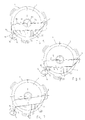
- the two Cams 14, 15 sit on a common shaft 16 which is driven by a motor 17 is. This arrangement is shown in more detail in FIG. 4. 4 is a possible one The shape of the cams is clearly visible.
- the motor 17 has a feedback Determination of the current alignment of the cams 14, 15, with the motor 17 as a rule Servomotor is designed.
- the two are Apertures 6, 7 in two mutually parallel, perpendicular to the optical axis X. Layers arranged swiveling. In order to image the cut-off line as sharply as possible to enable the lens 5 in the light direction Y in front of the reflector 2 and the diaphragms 6, 7 arranged that their focal point is as exact as possible with the planes of the diaphragms 6, 7 coincides. In order for this to be possible, in the present, practical embodiment the screens 6, 7 are designed as sheet-like components.
- the panels 6, 7 can actually be made of sheet metal, but also made of a suitable plastic, carbon fiber or ceramic be -, but rather describe the shape of the panels 6, 7, which as flat, flat components are formed, the thickness, i.e. essentially their spatial extent in light direction Y, as low as possible, especially with regard to the cross-sectional dimensions the apertures arranged in the beam path.
- the panels 6, 7, if possible have a small thickness to provide a clear image of the cut-off line in low beam and with a medium beam distribution pattern, such as a motorway light. In a simple way, a small thickness of the panels in the area of the top edges of the panel beveled in this area.
- the screens are generally designed as flat components. It can but also be appropriate - especially when using open space reflectors -, that the panels have a curved shape, which is a curvature the aperture is in the horizontal plane. This curvature may be necessary to get one to achieve a sharp image of the cut-off line.
- FIG. 5 is a front view of the headlight 1 according to the invention with a diaphragm position shown corresponding to a low beam, being behind the Aperture 6 of the reflector 2 is arranged.
- the lens 5 not shown in the drawing.
- the top edge 18 of the aperture 6, which acts as a light-dark boundary HD1 is mapped onto a roadway FB - see FIG. 8 for this purpose two substantially horizontal sections 18a, 18c on an inclined extending section 18b are interconnected.
- the lens side Aperture 7 is provided to generate an average beam distribution pattern LV2, which is shown schematically in FIG. 9.
- Such a pattern LV2 is represented by an aperture position, 6 in a front view of the headlight 1 according to the invention is achieved. From Fig. 6 it can be seen that for this purpose the lens-side diaphragm 7 an aperture edge 19 with an essentially continuous, horizontally extending Section that has a continuous light-dark boundary HD2 on the road FB maps.
- the positions of the lens and the reflector-side panel can be easily interchanged.
- a sub-beam distribution pattern is then no longer from the reflector side, but from the lens-side aperture is generated, in this case a medium beam distribution pattern no longer generated by the lens-side, but by the reflector-side aperture.
- the aperture position shown in FIGS. 1 and 7 generates a beam distribution pattern according to a high beam.
- the two panels 6, 7 are located in a lower one End position, so that in comparison to the diaphragm position shown in FIG. 2 or FIG light escaping from the headlight 1 additionally also one above the horizontal HH lying area can illuminate. This one, illuminated above the horizon
- the area is indicated by the curve HD3.
- the curve HD3 should not be considered understand a sharp transition between a light and a dark area, because with high beam the light distribution in the areas further in front of the vehicle shows no abrupt, but rather a continuous decrease in luminance.
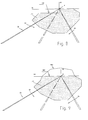
- FIGS. 8 and 9 show a beam distribution pattern LV1 of a low beam.
- a roadway FB which runs to a vanishing point FP, is also indicated a horizon HH and a vertical direction VV.
- the essentially illuminated area of the Lane FB is marked with LV1.
- FIG. 9 shows the light distribution LV2 of an average beam distribution pattern LV2.
- the light-dark boundary HD2 extends approximately to the horizon HH, which of course means a much better illumination of the roadway FB, in particular on the oncoming traffic side GV.
- this light distribution LV2 on the road FB is good visibility for the driver even at relatively high speeds or the vehicle occupants, without oncoming traffic even at a great distance dazzle.
- high beam shows a light distribution accordingly curve HD3 in FIG. 9. From FIG. 9 it can be seen that a not insignificant Part of the light distribution is already above the HH horizon, which on the one hand leads to a very good visibility, but on the other hand also to a strong glare of oncoming traffic leads, which are greatly reduced by using the motorway light described can.
- the roadway FB is essentially a two-lane road, approximately one Federal road shown.
- a medium beam distribution pattern also be designed so that the glare on oncoming traffic on a federal road is kept as low as possible.
- the main and most effective use of a medium Beam distribution pattern is undoubtedly given when used as a motorway light, since here usually a much higher driving speed than on a federal road prevails and thus in oncoming traffic, the low beam is switched on as it is Federal roads happen, too little illumination of the road brings with it.
- the lens-side diaphragm 7 is in an upper end position
- the reflector-side diaphragm 6, is in a position in which its Upper edge 18 of the aperture 7 with respect to the beam projection onto the roadway FB is completely covered.
- the light-dark boundary HD2 is thus complete in this case generated by the top edge 19 of the aperture 7.
- Beam distribution patterns LV2 as shown schematically in FIG. 9, are generated, which a road illumination similar to that of a high beam can be achieved without to show the strong glare of high beam for oncoming traffic.
- the panels 6, 7 are movable between the different positions, they are on one end mounted on the pivot axis 8, at the other end they each have one Scanning nose 10, 11, which by means of spring force 21, 22 against the sliding surfaces 12, 13 of the assigned cams 14, 15 are pressed.
- the two cams 14, 15 are on one arranged common shaft 16 which is driven by the motor 17.
- the cams 14, 15 are eccentric shaped, as can be seen from FIGS. 1-7.
- cams 14, 15 are arranged offset from one another, it can be achieved that when the shaft 16 is rotated by means of the motor 17, that aperture, the scanning nose attacks the cam assigned to it in an area with eccentricity, in the vertical direction is moved, but the other aperture, the scanning nose on a circular Attacks the area of the cam, does not experience any movement in the vertical direction. This way and This ensures that there is a smooth, continuous transition between the individual beam distribution patterns is possible without the transition between two Beam distribution patterns cause unwanted interference.
- the scanning nose 10 attacks the reflector-side diaphragm 6 a circular area of the cam 14, while the scanning lug 11 of the lens side Aperture 7 is located in an eccentric area of cam 15.
- the Wave 16 counterclockwise - when looking in the opposite direction of light Y - the aperture 7 is pivoted upwards until its scanning lug in the circular area the cam 15 arrives.
- the pivoting movement of the panel 7 has now ended, the panel 7 is at its highest point.
- the scanning lug 10 of the diaphragm 6 still engages circular area of the cam 14, the aperture 6 thus experiences at the beginning of the rotary movement the shaft 16 still no vertical movement. This ensures that not short term undesirable when transitioning from one beam distribution pattern to another Interfering effects, such as the high beam lighting up during the transition from low-beam to low-beam Autobahn light, occur. Only when the aperture 7 has reached its uppermost position gradually begins the downward movement of the diaphragm 6 to a lower position.
- the height adjustment of the panels can also be done automatically, depending on one Vehicle speed. This makes it necessary to adapt the road illumination possible at the current vehicle speed. Research has shown that the driver's attention especially to those on the light-dark boundary Area of the roadway is directed. It can therefore be useful when driving on a motorway be when the range of the illumination is automatic at a lower speed is reduced, for example, to the driver's attention to that area to steer the vehicle, which is approximately that at the prevailing speed necessary braking distance for stopping in front of an obstacle.
- the adjustment of the Aperture takes place via electronics known to the person skilled in the art, which are the motor controls according to the vehicle speed and the respective aperture in that position moves, which generates a light distribution corresponding to the speed.
- the embodiment of the invention described above is particularly advantageous simple and inexpensive construction.
- To turn the two cams 14, 15 is a only motor 17 is provided, thereby reducing the manufacturing cost of the invention Headlights can be kept low compared to other headlights.
- Another advantageous aspect is that switching between different Beam distribution patterns are essentially silent. This can be attributed to this that the transition between the different aperture positions takes place continuously and the shutters are held in the desired position via the cams become. With other headlights with an adjustable cover, however, the cover snaps in an end position or is moved against a stop, which is often characterized by a unpleasant click noticeable.
- the mode of operation of the invention also extends to three or more Apertures can be used to generate four or more beam distribution patterns can, the cams necessary for height adjustment of the diaphragms in turn on a common shaft can sit and are driven by only one motor. It only has to care must be taken that the cams are shaped accordingly and with regard to their eccentricity are offset from one another so that there is a continuous transition between the individual Beam distribution patterns is possible.
- each pair of diaphragms or each diaphragm has its own shaft associated cam is driven.
- the advantage of using multiple shafts is that when switching between two beam distribution patterns, a brief switch-on an undesirable beam distribution pattern - such as when using three or more apertures, which by means of cams that are on a common driven shaft are arranged, is inevitable -, can be avoided.
- this is one Embodiment is more expensive to manufacture and requires more installation space.
- the invention can also be used when only one height-adjustable screen is of great advantage because of the use a cam for moving the diaphragms to switch between two beam distribution patterns - As already mentioned above - almost silent and for the vehicle occupants is no longer perceptible acoustically.
- the beam distribution pattern Low beam / high beam or motorway light / high beam can be generated.
Landscapes
- Engineering & Computer Science (AREA)
- General Engineering & Computer Science (AREA)
- Non-Portable Lighting Devices Or Systems Thereof (AREA)
- Lighting Device Outwards From Vehicle And Optical Signal (AREA)
Applications Claiming Priority (2)
| Application Number | Priority Date | Filing Date | Title |
|---|---|---|---|
| AT0128399A ATA128399A (de) | 1999-07-23 | 1999-07-23 | Scheinwerfer für kraftfahrzeuge |
| AT128399 | 1999-07-23 |
Publications (2)
| Publication Number | Publication Date |
|---|---|
| EP1070911A2 true EP1070911A2 (fr) | 2001-01-24 |
| EP1070911A3 EP1070911A3 (fr) | 2005-12-28 |
Family
ID=3510546
Family Applications (1)
| Application Number | Title | Priority Date | Filing Date |
|---|---|---|---|
| EP00890214A Withdrawn EP1070911A3 (fr) | 1999-07-23 | 2000-07-10 | Projecteur pour véhicules automobiles |
Country Status (2)
| Country | Link |
|---|---|
| EP (1) | EP1070911A3 (fr) |
| AT (1) | ATA128399A (fr) |
Cited By (13)
| Publication number | Priority date | Publication date | Assignee | Title |
|---|---|---|---|---|
| DE10125463A1 (de) * | 2001-05-25 | 2002-11-28 | Hella Kg Hueck & Co | Projektionsmodul für einen Fahrzeugscheinwerfer |
| EP1798468A3 (fr) * | 2005-12-15 | 2007-08-22 | Hella KG Hueck & Co. | Projecteur pour véhicule |
| CZ299344B6 (cs) * | 2003-09-10 | 2008-06-25 | Visteon Glogal Technologies, Inc. | Multifunkcní adaptivní projektorový systém pro motorová vozidla |
| DE102008001094A1 (de) | 2007-05-21 | 2008-11-27 | Zizala Lichtsysteme Gmbh | Blendenanordnung für eine Lichteinheit bzw. einen Scheinwerfer eines Kraftfahrzeugs |
| EP2088365A2 (fr) | 2006-09-27 | 2009-08-12 | Volkswagen AG | Phare pour véhicule |
| DE102009027702A1 (de) | 2008-08-13 | 2010-02-18 | Saia-Burgess Murten Ag | Einstellvorrichtung zum Bewegen einer Einstellkomponente mit einem Elektroantrieb |
| EP2196731A1 (fr) * | 2008-12-12 | 2010-06-16 | Valeo Vision | Module optique de projecteur automobile avec cache mobile |
| CN101915402A (zh) * | 2010-07-05 | 2010-12-15 | 奇瑞汽车股份有限公司 | 一种自适应前照灯执行机构 |
| EP2357400A1 (fr) * | 2010-02-09 | 2011-08-17 | Raiderson Enterprise Co.,Ltd. | Dispositif de commande d'un faisceau à forte et faible intensité pour un phare |
| DE102005012303B4 (de) * | 2005-03-17 | 2015-11-26 | Automotive Lighting Reutlingen Gmbh | Scheinwerfer |
| CN106813186A (zh) * | 2017-04-10 | 2017-06-09 | 海纳川海拉(三河)车灯有限公司 | 车用led近光模组及其使用方法 |
| DE102007045150B4 (de) * | 2006-09-27 | 2021-03-04 | HELLA GmbH & Co. KGaA | Scheinwerferanordnung für ein Fahrzeug und Verfahren zum Steuern einer Scheinwerferanordnung |
| CN113167936A (zh) * | 2018-12-10 | 2021-07-23 | 海拉有限双合股份公司 | 用于制造光学构件的方法、光学构件以及用于机动车的照明设备 |
Citations (3)
| Publication number | Priority date | Publication date | Assignee | Title |
|---|---|---|---|---|
| DE4335286A1 (de) | 1992-10-21 | 1994-04-28 | Koito Mfg Co Ltd | Projektionsscheinwerfer für Kraftfahrzeuge |
| DE4243174A1 (de) | 1992-12-19 | 1994-06-23 | Bosch Gmbh Robert | Scheinwerfer für Fahrzeuge |
| AT404396B (de) | 1996-12-05 | 1998-11-25 | Zizala Lichtsysteme Gmbh | Rillenscheinwerfer |
Family Cites Families (4)
| Publication number | Priority date | Publication date | Assignee | Title |
|---|---|---|---|---|
| US2015935A (en) * | 1934-11-19 | 1935-10-01 | Ray D Smith | Head lamp for vehicles |
| DE3926455A1 (de) * | 1989-08-10 | 1991-02-14 | Hella Kg Hueck & Co | Scheinwerfer fuer fahrzeuge |
| DE19537838A1 (de) * | 1995-10-11 | 1997-04-17 | Bosch Gmbh Robert | Scheinwerfer für Fahrzeuge |
| DE19708111A1 (de) * | 1997-02-28 | 1998-09-03 | Hella Kg Hueck & Co | Fernbetätigbares Einstellsystem |
-
1999
- 1999-07-23 AT AT0128399A patent/ATA128399A/de not_active Application Discontinuation
-
2000
- 2000-07-10 EP EP00890214A patent/EP1070911A3/fr not_active Withdrawn
Patent Citations (3)
| Publication number | Priority date | Publication date | Assignee | Title |
|---|---|---|---|---|
| DE4335286A1 (de) | 1992-10-21 | 1994-04-28 | Koito Mfg Co Ltd | Projektionsscheinwerfer für Kraftfahrzeuge |
| DE4243174A1 (de) | 1992-12-19 | 1994-06-23 | Bosch Gmbh Robert | Scheinwerfer für Fahrzeuge |
| AT404396B (de) | 1996-12-05 | 1998-11-25 | Zizala Lichtsysteme Gmbh | Rillenscheinwerfer |
Cited By (17)
| Publication number | Priority date | Publication date | Assignee | Title |
|---|---|---|---|---|
| DE10125463A1 (de) * | 2001-05-25 | 2002-11-28 | Hella Kg Hueck & Co | Projektionsmodul für einen Fahrzeugscheinwerfer |
| CZ299344B6 (cs) * | 2003-09-10 | 2008-06-25 | Visteon Glogal Technologies, Inc. | Multifunkcní adaptivní projektorový systém pro motorová vozidla |
| DE102005012303B4 (de) * | 2005-03-17 | 2015-11-26 | Automotive Lighting Reutlingen Gmbh | Scheinwerfer |
| EP1798468A3 (fr) * | 2005-12-15 | 2007-08-22 | Hella KG Hueck & Co. | Projecteur pour véhicule |
| EP2088365A2 (fr) | 2006-09-27 | 2009-08-12 | Volkswagen AG | Phare pour véhicule |
| EP2088365A3 (fr) * | 2006-09-27 | 2010-01-13 | Volkswagen AG | Phare pour véhicule |
| DE102007045150B4 (de) * | 2006-09-27 | 2021-03-04 | HELLA GmbH & Co. KGaA | Scheinwerferanordnung für ein Fahrzeug und Verfahren zum Steuern einer Scheinwerferanordnung |
| DE102008001094A1 (de) | 2007-05-21 | 2008-11-27 | Zizala Lichtsysteme Gmbh | Blendenanordnung für eine Lichteinheit bzw. einen Scheinwerfer eines Kraftfahrzeugs |
| DE102009027702A1 (de) | 2008-08-13 | 2010-02-18 | Saia-Burgess Murten Ag | Einstellvorrichtung zum Bewegen einer Einstellkomponente mit einem Elektroantrieb |
| EP2196731A1 (fr) * | 2008-12-12 | 2010-06-16 | Valeo Vision | Module optique de projecteur automobile avec cache mobile |
| FR2939869A1 (fr) * | 2008-12-12 | 2010-06-18 | Valeo Vision Sas | Module optique de projecteur automobile avec cache mobile |
| EP2357400A1 (fr) * | 2010-02-09 | 2011-08-17 | Raiderson Enterprise Co.,Ltd. | Dispositif de commande d'un faisceau à forte et faible intensité pour un phare |
| CN101915402A (zh) * | 2010-07-05 | 2010-12-15 | 奇瑞汽车股份有限公司 | 一种自适应前照灯执行机构 |
| CN101915402B (zh) * | 2010-07-05 | 2012-11-28 | 奇瑞汽车股份有限公司 | 一种自适应前照灯执行机构 |
| CN106813186A (zh) * | 2017-04-10 | 2017-06-09 | 海纳川海拉(三河)车灯有限公司 | 车用led近光模组及其使用方法 |
| CN113167936A (zh) * | 2018-12-10 | 2021-07-23 | 海拉有限双合股份公司 | 用于制造光学构件的方法、光学构件以及用于机动车的照明设备 |
| CN113167936B (zh) * | 2018-12-10 | 2023-04-28 | 海拉有限双合股份公司 | 用于制造光学构件的方法、光学构件以及用于机动车的照明设备 |
Also Published As
| Publication number | Publication date |
|---|---|
| EP1070911A3 (fr) | 2005-12-28 |
| ATA128399A (de) | 2005-09-15 |
Similar Documents
| Publication | Publication Date | Title |
|---|---|---|
| EP2039567B1 (fr) | Agencement de phare de projection pour véhicules | |
| EP2069685B1 (fr) | Ensemble phare pour un véhicule et procédé de commande associé | |
| DE19860461B4 (de) | Scheinwerferanlage für Fahrzeuge zur Erzeugung von Lichtbündeln mit unterschiedlicher Charakteristik | |
| DE102007045150B4 (de) | Scheinwerferanordnung für ein Fahrzeug und Verfahren zum Steuern einer Scheinwerferanordnung | |
| DE19961942C5 (de) | Scheinwerferanlage für Fahrzeuge zur Erzeugung von Lichtbündeln mit unterschiedlicher Charakteristik | |
| EP1234716B1 (fr) | Phare de véhicule | |
| DE102008053947B4 (de) | Fahrzeugleuchtensystem | |
| EP0937942A2 (fr) | Phare du type projecteur | |
| DE102005012303B4 (de) | Scheinwerfer | |
| DE102008014182A1 (de) | Verfahren zur Fahrlichtsteuerung eines Fahrzeugs | |
| DE10044392B4 (de) | Fahrzeugscheinwerfer | |
| DE102005011650A1 (de) | Projektionsfahrzeugscheinwerfer | |
| DE19946350A1 (de) | Projektionsscheinwerfer und Beleuchtungsvorrichtung für Fahrzeuge mit derartigen Scheinwerfern | |
| DE102007007839A1 (de) | Fahrzeugscheinwerfer | |
| DE4306316A1 (en) | Reflector positioner e.g. for varying vehicle headlamp light distribution - involves servomotor in controlled movement of reflector guided by pins engaging in grooves of fixed plate | |
| EP1070911A2 (fr) | Projecteur pour véhicules automobiles | |
| DE4314332A1 (de) | Scheinwerfer mit vier lampen und variablem lichtstrahlmuster | |
| DE69709200T2 (de) | Fahrzeugscheinwerfer mit einziger Lichtquelle für Ablendlicht und Fernlicht | |
| DE102004045881A1 (de) | Scheinwerfer | |
| AT504793B1 (de) | Blendenanordnung für eine lichteinheit bzw. einen scheinwerfer eines kraftfahrzeugs | |
| DE19844839B4 (de) | Scheinwerfer für Fahrzeuge | |
| DE102011121603A1 (de) | Scheinwerferanordnung für ein Fahrzeug und Verfahren zum Herstellen einer Scheinwerferanordnung in einem Fahrzeug | |
| EP1398210A2 (fr) | Projecteur pour véhicule | |
| DE10012923A1 (de) | Scheinwerfer für Fahrzeuge und Steuervorrichtung | |
| DE102004051485A1 (de) | Fahrzeugscheinwerfer |
Legal Events
| Date | Code | Title | Description |
|---|---|---|---|
| PUAI | Public reference made under article 153(3) epc to a published international application that has entered the european phase |
Free format text: ORIGINAL CODE: 0009012 |
|
| AK | Designated contracting states |
Kind code of ref document: A2 Designated state(s): AT BE CH CY DE DK ES FI FR GB GR IE IT LI LU MC NL PT SE |
|
| AX | Request for extension of the european patent |
Free format text: AL;LT;LV;MK;RO;SI |
|
| PUAL | Search report despatched |
Free format text: ORIGINAL CODE: 0009013 |
|
| AK | Designated contracting states |
Kind code of ref document: A3 Designated state(s): AT BE CH CY DE DK ES FI FR GB GR IE IT LI LU MC NL PT SE |
|
| AX | Request for extension of the european patent |
Extension state: AL LT LV MK RO SI |
|
| STAA | Information on the status of an ep patent application or granted ep patent |
Free format text: STATUS: THE APPLICATION IS DEEMED TO BE WITHDRAWN |
|
| 18D | Application deemed to be withdrawn |
Effective date: 20060201 |