EP1072425B1 - Control unit and method for controlling motor for use in printer and storage medium storing control program - Google Patents
Control unit and method for controlling motor for use in printer and storage medium storing control program Download PDFInfo
- Publication number
- EP1072425B1 EP1072425B1 EP00306297A EP00306297A EP1072425B1 EP 1072425 B1 EP1072425 B1 EP 1072425B1 EP 00306297 A EP00306297 A EP 00306297A EP 00306297 A EP00306297 A EP 00306297A EP 1072425 B1 EP1072425 B1 EP 1072425B1
- Authority
- EP
- European Patent Office
- Prior art keywords
- speed
- motor
- printer
- controlling
- detected
- Prior art date
- Legal status (The legal status is an assumption and is not a legal conclusion. Google has not performed a legal analysis and makes no representation as to the accuracy of the status listed.)
- Expired - Lifetime
Links
- 238000000034 method Methods 0.000 title claims description 20
- 239000000976 ink Substances 0.000 description 25
- 238000010276 construction Methods 0.000 description 18
- 230000015654 memory Effects 0.000 description 15
- 230000001133 acceleration Effects 0.000 description 14
- 238000010586 diagram Methods 0.000 description 8
- 238000007599 discharging Methods 0.000 description 5
- 230000000694 effects Effects 0.000 description 3
- 238000001514 detection method Methods 0.000 description 2
- 230000010354 integration Effects 0.000 description 2
- 230000003287 optical effect Effects 0.000 description 2
- 230000002093 peripheral effect Effects 0.000 description 2
- 101000793686 Homo sapiens Azurocidin Proteins 0.000 description 1
- 230000007423 decrease Effects 0.000 description 1
- 239000006185 dispersion Substances 0.000 description 1
- 239000000428 dust Substances 0.000 description 1
- 238000012986 modification Methods 0.000 description 1
- 230000004048 modification Effects 0.000 description 1
- 239000000843 powder Substances 0.000 description 1
- 230000001172 regenerating effect Effects 0.000 description 1
- 238000007789 sealing Methods 0.000 description 1
- 230000001629 suppression Effects 0.000 description 1
Images


Classifications
-
- B—PERFORMING OPERATIONS; TRANSPORTING
- B41—PRINTING; LINING MACHINES; TYPEWRITERS; STAMPS
- B41J—TYPEWRITERS; SELECTIVE PRINTING MECHANISMS, i.e. MECHANISMS PRINTING OTHERWISE THAN FROM A FORME; CORRECTION OF TYPOGRAPHICAL ERRORS
- B41J19/00—Character- or line-spacing mechanisms
- B41J19/18—Character-spacing or back-spacing mechanisms; Carriage return or release devices therefor
- B41J19/20—Positive-feed character-spacing mechanisms
- B41J19/202—Drive control means for carriage movement
Definitions
- the present invention relates generally to a control unit and method for controlling a motor for use in a printer, and a storage medium storing a control program. More specifically, the invention is used for controlling the speed of a motor for driving a carriage of a serial printer.
- a recording head scans on a printing paper to print.
- This recording head is fixed to a carriage to move with the carriage.
- This carriage is driven by a DC (Direct Current) motor.
- the system for driving the carriage is as follows.
- a timing belt is stretched at a predetermined tension between a driving pulley, which is fixed to the rotating shaft of the DC motor, and a driven wheel which is a companion to the driving pulley.
- the carriage is mounted on the timing belt.
- the carriage is driven by the rotation of the DC motor so as to move main scanning directions.
- the speed control for causing the speed of the DC motor to be a constant speed is carried out by a PID control based on the deviation of a detected actual speed from a target speed.
- a typical DC motor has a stator 210 and a rotor 220.
- the stator 210 comprises a yoke 210a and a magnetic pole 210b.
- the rotor 220 comprises a protruding portion 220a which serves as a magnetic pole of an electromagnet, and a coil 220b which is wound onto the base portion of the protruding portion 220a.
- the rotor 220 is designed to sequentially switch the polarity of the electromagnet by the operation of a commutator 230 and a brush 240. Therefore, the DC motor has the fluctuation in torque.
- the number of phases of the DC motor (the number of coils, i.e., the number of the base portions of the protruding portions 220a) is p
- the fluctuation in torque occurs 2p times while the DC motor makes one rotation.
- the number of phases of the DC motor is 3 in FIG. 13.
- US Patent No. 5748206 discloses a printer, wherein a variation in the moving speed of a carriage, mainly due to the variation of the mass of the carriage with the consumption of ink is corrected every printing cycle to enhance the accuracy of printing.
- a control unit for controlling a motor in a printer, said control unit comprising: a speed detecting part for detecting a speed of said motor in a predetermined period t v ; an average speed calculating part for calculating an average speed based on, from said speed detecting part, a current detected speed and a previously detected speed which has been detected n ( ⁇ 2) periods t v before a detecting of said current speed corresponding to a substantially half period of a fluctuation in speed of said motor; and a speed control part (6f, 6h) for controlling the speed of said motor on the basis of a speed deviation of said average speed from a target speed of said motor.
- the number n used for calculating the average speed preferably meets the following expression. T v / ( 2 t v ) - 2 ⁇ n ⁇ T v / ( 2 t v ) + 2
- the average speed calculating part preferably calculates an average speed of k+1 detected speeds from the current detected speed to a detected speed of k (n > k ⁇ 0) before, and k+1 detected speeds from a detected speed of n before to a detected speed of k+1 before.
- the speed control part preferably has a differentiating element which operates on the basis of the speed deviation of the average speed from the target speed.
- the speed control part may have a proportional element which operates on the basis of the speed deviation of the average speed from the target speed.
- the speed detecting part may comprise an encoder for generating an output pulse in accordance with the rotation of the motor, and a speed calculating part for calculating the speed of the motor in a period of the output pulse on the basis of the output pulse of the encoder.
- the motor may be a carriage motor for use in an ink jet printer, and the encoder may generate the output pulse in accordance with the movement of a carriage driven by the carriage motor via a pulley, which is mounted of the rotating shaft of the carriage motor, and via a timing belt which is driven by the pulley.
- the n meets the following expression. L / ( 4 p ⁇ ) ⁇ n ⁇ L / ( 4 p ⁇ ) + 2
- the speed control part may further comprise: a second speed calculating part for calculating the speed of the motor in a second predetermined period on the basis of the output pulse of the encoder; a second average speed calculating part for calculating the average speed using at least the current calculated speed, which is calculated by the second speed calculating part, and a calculated speed which has been m (m ⁇ 2) before; and a second differentiating element which operates on the basis of a speed deviation of the output of the second average speed calculating part from the target speed.
- the motor may be a DC motor.
- a method for controlling a motor in a printer comprising the steps of: detecting a speed of said motor in a predetermined period t v ; calculating an average speed based on, from said detecting, a current detected speed and on a previously detected speed which has been detected n ( ⁇ 2) periods t v before said detecting of said current speed corresponding to a substantially half period of a fluctuation in speed of said motor; and controlling the speed of said motor on the basis of a speed deviation of said average speed from a target speed of said motor.
- the number n used for calculating the average speed preferably meets the following expression. T v / ( 2 t v ) - 2 ⁇ n ⁇ T v / ( 2 t v ) + 2
- the step of controlling the speed of the motor controls the speed of the motor on the basis of the sum of the speed deviation and the output of a differentiating element which operates on the basis of the speed deviation.
- a computer-readable storage medium storing control program code for controlling a motor in a printer, comprising: first program code means for detecting the speed of said motor in a predetermined period t v ; second program code means for calculating an average speed using at least a current detected speed and a detected speed which has been detected n ( ⁇ 2) periods t v before a time when said current speed is detected, corresponding to a substantially half period of a fluctuation in speed of said motor; and third program code means for controlling the speed of said motor on the basis of a speed deviation of said average speed from a target speed of said motor.
- This ink jet printer comprises: a paper feed motor (which will be also hereinafter referred to as a PF motor) 1 for feeding a paper; a paper feed motor driver 2 for driving the paper feed motor 1; a carriage 3; a carriage motor (which will be also hereinafter referred to as a CR motor) 4; a CR motor driver 5 for driving the carriage motor 4; a DC unit 6; a pump motor 7 for controlling the suction of ink for preventing clogging; a pump motor driver 8 for driving the pump motor 7; a recording head 9, fixed to the carriage 3, for discharging ink to a printing paper 50; a head driver 10 for driving and controlling the recording head 9; a linear type encoder 11 fixed to the carriage 3; a code plate 12 which has slits in regular intervals; a rotary type encoder 13 for use in the PF motor 1; a paper detecting sensor 15 for detecting the position of the rear edge of a paper which is being printed; a CPU 16 for controlling the whole printer; a
- each of the paper feed motor 1 and the CR motor 4 comprises a DC motor.
- FIG. 7 The peripheral construction of the carriage 3 of this ink jet printer is shown in FIG. 7.
- the carriage 3 is connected to the carriage motor 4 via the timing belt 31 and the pulley 30 to be driven so as to be guided by a guide member 32 to move in parallel to the platen 25.
- the carriage 3 is provided with the recording head 9 on the surface facing the printing paper.
- the recording head 9 comprises a nozzle row for discharging a black ink and a nozzle row for discharging color inks. Each nozzle is supplied with ink from an ink cartridge 34, and discharges drops of ink to the printing paper to print characters and/or images.
- a capping unit 35 for sealing a nozzle opening of the recording head 9 during non-print
- a pump unit 36 having the pump motor 7 shown in FIG. 6.
- the pump unit 36 When the nozzle opening row of the recording head 9 is clogged with ink, or when the cartridge 34 is exchanged or the like to force the recording head 9 to discharge ink, the pump unit 36 is operated in the sealed state of the recording head 9, to suck ink out of the nozzle opening row by a negative pressure from the pump unit 36. Thus, dust and paper powder adhering to a portion near the nozzle opening row are cleaned. Moreover, bubbles of the recording head 9, together with ink, are discharged to a cap 37.
- This encoder 11 comprises a light emitting diode 11a, a collimator lens 11b, and a detection processing part 11c.
- the detection processing part 11c has a plurality of (four) photodiodes 11d, a signal processing circuit 11e, and two comparators 11f A and 11f B .
- the parallel rays passing through the code plate 12 are incident on each of the photodiodes 11d via a fixed slit (not shown), and converted into electric signals.
- the electric signals outputted from the four photodiodes 11d are processed by the signal processing circuit 11e.
- the signals outputted from the signal processing circuit 11e are compared by the comparators 11f A and 11f B , and the compared results are outputted as pulses.
- the pulses ENC-A and ENC-B outputted from the comparators 11f A and 11f B are outputs of the encoder 11.
- the phase of the pulse ENC-A is different from the phase of the pulse ENC-B by 90 degrees.
- the encoder 4 is designed so that the phase of the pulse ENC-A is advanced from the pulse ENC-B by 90 degrees as shown in FIG. 9(a) when the CR motor 4 is normally rotating, i.e., when the carriage 3 is moving a main scanning direction, and the phase of the pulse ENC-A lags behind the pulse ENC-B by 90 degrees as shown in FIG. 9(b) when the CR motor 4 is reversely rotating.
- the paper 10 inserted into a paper feeding port 61 of a printer 60 is fed into the printer 60 by means of a paper feeding roller 64 which is driven by a paper feeding motor 63.
- the front edge of the paper 50, which has been fed into the printer 60 is detected by, e.g., an optical paper detecting sensor 15.
- the paper 50, the front edge of which has been detected by the paper detecting sensor 15, is fed by means of a paper feed roller 65 and a driven roller 66 which are driven by the PF motor 1.
- the DC unit 6 comprises a position calculating part 6a, a subtracter 6b, a target speed calculating part 6c, a speed calculating part 6d, a subtracter 6e, a proportional element 6f, an integrating element 6g, a differentiating element 6h, an adder 6i, a D/A converter 6j, a timer 6k, and an acceleration control part 6m.
- the position calculating part 6a is designed to detect the leading and trailing edges of each of the output pulses ENC-A and ENC-B of the encoder 11 to count the number of the detected edges, and to calculate the position of the carriage 3 on the basis of the counted value. In this counting, when the CR motor 4 is normally rotating, if one edge is detected, "+1" is added, and when the CR motor 4 is reversely rotating, if one edge is detected, "-1" is added.
- Each of the periods of the pulses ENC-A and ENC-B is equal to the distance between adjacent slits of the code plate 12, and the phase of the pulse ENC-A is different from the phase of the pulse ENC-B by 90 degrees.
- the counted value "1" in the above described counting corresponds to 1/4 of the distance between adjacent slits of the code plate 12.
- the subtracter 6b is designed to calculate a position deviation of the actual position of the carriage 3, which is obtained by the position calculating part 6a, from a target position which is fed from the CPU 16.
- the target speed calculating part 6c is designed to calculate a target speed of the carriage 3 on the basis of the position deviation which is the output of the subtracter 6b. This operation is carried out by multiplying the position deviation by a gain K p .
- This gain K p is determined in accordance with the position deviation. Furthermore, the value of the gain K p may be stored in a table (not shown).
- the subtracter 6e is designed to calculate a speed deviation of the actual speed of the carriage 3, which is calculated by the speed calculating part 6d, from a target speed.
- the proportional element 6f is designed to multiply the speed deviation by a constant Gp to output the multiplied result.
- the integrating element 6g is designed to integrate a value which is obtained by multiplying the speed deviation by a constant Gi.
- the differentiating element 6h is designed to multiply a difference between the current speed deviation and the last speed variation by a constant Gd to output the multiplied result. Furthermore, the operations in the proportional element 6f, integrating element 6g and differentiating element 6h are carried out every one period of the output pulse ENC-A of the encoder 11, i.e., in synchronism with the leading edge of the output pulse ENC-A.
- the outputs of the proportional element 6f, integrating element 6g and differentiating element 6h are added by the adder 6i. Then, the added result, i.e., the driving current of the CR motor 4, is fed to the D/A converter 6j to be converted into an analog current. On the basis of the analog current, the CR motor 4 is driven by the driver 5.
- timer 6k and the acceleration control part 6m are used for controlling acceleration
- PID control using the proportional element 6f, integrating element 6g and differentiating element 6h is used for controlling the constant speed and deceleration during acceleration.
- the timer 6k is designed to generate a timer interruption signal every a predetermined time on the basis of a clock signal which is fed from the CPU 16.
- the acceleration control part 6m is designed to integrate a predetermined current value (e.g., 20 mA) into a target current value every time it receives the timer interruption signal, and to feed the integrated result, i.e., the target current value of the DC motor 4 during acceleration, to the D/A converter 6j. Similar to the PID control, the target current value is converted into an analog current by the D/A converter 6j. On the basis of this analog current, the CR motor 4 is driven by the driver.
- a predetermined current value e.g. 20 mA
- the driver 5 has, e.g., four transistors. By turning each of the transistors ON and OFF on the basis of the output of the D/A converter 6j, the driver 5 can be selectively in (a) an operation mode in which the CR motor 4 is normally or reversely rotated, (b) a regenerative brake operation mode (a short brake operation mode, i.e., a mode in which the stopping of the CR motor is maintained), or (c) a mode in which the CR motor is intended to be stopped.
- a regenerative brake operation mode a short brake operation mode, i.e., a mode in which the stopping of the CR motor is maintained
- a mode in which the CR motor is intended to be stopped.
- a start-up initial current value I o is fed from the acceleration control part 6m to the D/A converter 6j. Furthermore, this start-up initial current value I o , together with the start-up command signal, is fed from the CPU 16 to the acceleration control part 6m. Then, this current value I o is converted into an analog current by the D/A converter 6j to be fed to the driver 5, and the CR motor is started up by the driver 5 (see FIG. 12(a), 12(b)).
- the timer 6k After the start-up command signal is received, the timer 6k generates a timer interruption signal every a predetermined time. Every time the acceleration control part 6m receives the timer interruption signal, the acceleration control part 6m integrates a predetermined current value (e.g., 20 mA) into the start-up initial current value I o , to feed the integrated current value to the D/A converter 6j. Then, the integrated current value is converted into an analog current by the D/A converter 6j to be fed to the driver 5. Then, the CR motor is driven by the driver 5 so that the value of the current supplied to the CR motor 4 is the integrated current value, so that the speed of the CR motor 4 increases (see FIG. 12(b)). Therefore, the current value supplied to the CR motor is step-wise as shown in FIG. 12(a).
- a predetermined current value e.g. 20 mA
- the D/A converter 6j selects and incorporates the output of the acceleration control part 6m.
- the integration of the current value in the acceleration control part 6m is carried out until the integrated current value becomes a constant current value I s .
- the acceleration control part 6m stops the integration, and supplies the constant current value I s to the D/A converter 6j.
- the CR motor 4 is driven by the driver 5 so that the value of the current supplied to the CR motor 4 becomes the current value I s (see FIG. 12(a)).
- the acceleration control part 6m controls the CR motor 4 so as to reduce the current, which is supplied to the CR motor 4, when the speed of the CR motor 4 becomes a predetermined speed V 1 (see time t 2 ). At this time, the speed of the CR motor 4 further increases. However, when the speed of the CR motor 4 reaches a predetermined speed V c (see time t 3 in FIG. 12(b)), the D/A converter 6j selects the output of the PID control system, i.e., the output of the adder 6i, to carry out the PID control.
- the target speed is calculated on the basis of the position deviation of the actual position, which is obtained from the output of the encoder 11, from the target position.
- the proportional element 6f, integrating element 6g and differentiating element 6h are operated on the basis of the speed deviation of the actual speed, which is obtained from the output of the encoder 11, from the target speed to carry out the proportional, integrating and differentiating operations.
- the CR motor 4 is controlled on the basis of the sum of these calculated results.
- the above described proportional, integrating and differentiating operations are carried out in synchronism with, e.g., the leading edge of the output pulse ENC-A of the encoder 11..
- the speed of the DC motor 4 is controlled so as to be a desired speed V e .
- the predetermined speed V c is preferably a value of 70 % to 80 % of the desired speed V e .
- the construction of the first preferred embodiment of a control unit for controlling a motor for use in a printer according to the present invention is shown in FIG. 1.
- the control unit in this preferred embodiment is used for controlling a carriage motor 4 comprising a DC motor for use in an ink jet printer, and comprises a DC unit 80.
- the DC unit 80 includes an average speed measuring part 90, which is substituted for the speed calculating part 6d of the DC unit 6 shown in FIG. 11, and a subtracter 96 which is newly provided.
- the average speed measuring part 90 comprises a speed calculating part 91, a memory 92, and an average speed calculating part 93.
- the speed calculating part 91 has the same construction as that of the speed calculating part 6d shown in FIG. 11.
- the speed calculating part 91 is designed to calculate a speed of the CR motor 4, i.e., a speed of the carriage 3, on the basis of the output of the encoder 11.
- This operation is carried out in synchronism with the leading edge of the output pulse ENC-A of the encoder 11.
- the memory 92 is designed to store therein n speed data from the last calculated result to a calculated result of n (n ⁇ 1) before, which have been calculated by the speed calculating part 91. After the average speed calculating part 93 reads n speed data, the memory 92 is designed to store therein the current speed which is calculated by the speed calculating part 91 in place of the calculated speed of n before.
- the average speed calculating part 93 is designed to calculate an average of two speed data of the current speed data, which are calculated by the speed calculating part 91, and speed data of n before, which have been stored in the memory 92.
- the subtracter 6e is designed to calculate a speed deviation of the current speed, which is calculated by the speed calculating part 91, from a target speed, which is the output of the target speed calculating part 6c, to transmit the calculated speed deviation to the integrating element 6g.
- the subtracter 96 is designed to calculate a speed deviation of the average speed, which is the output of the average speed calculating part 93, from the target speed, which is the output of the target speed calculating part 6c, to transmit the calculated speed deviation to the proportional element 6f and the differentiating element 6h.
- the proportional element 6f is designed to multiply the output of the subtracter 96 by a constant Gp to transmit the multiplied result to the adder 6i.
- the integrating element 6g is designed to integrate a value, which has been obtained by multiplying the output of the subtracter 6e by a constant Gi, to transmit the integrated result to the adder 6i.
- the differentiating element 6h is designed to multiply a difference between the current speed deviation and the last speed deviation by a constant Gd to transmit the multiplied result to the adder 6i. Furthermore, the operations in the proportional element 6f, integrating element 6g and differentiating element 6h are carried out in synchronism with the leading edge of the output pulse ENC-A of the encoder 11.
- the outputs of the proportional element 6f, integrating element 6g and differentiating element 6h are added up by the adder 6i. Then, the added result, i.e., the current for driving the CR motor 4 which causes the above described speed deviation to be zero, is fed to the D/A converter 6j to be converted an analog current. On the basis of this analog current, the CR motor 4 is driven by the driver 5.
- the number n used for calculating the average speed approximates to T v / (2t v ) assuming that the period of the fluctuation in speed of the CR motor 4 is T v and that the period of the operation of the speed in the speed calculating part 91 is t v .
- the number n used for calculating the average speed preferably meets the following expression.
- the same effects can be obtained if the speed deviation is inputted to only the differentiating element 6h and if the speed deviation of the output of the speed calculating part 91 from the target speed is inputted to the proportional element 6f and the integrating element 6f.
- the same effects can be obtained if the speed deviation of the average speed from the target speed is inputted to all of the proportional element 6f, the integrating element 6g and the differentiating element 6h.
- the position calculating part 6a has counted the leading and trailing edges of the output pulses ENC-A and ENC-B of the encoder 11 to multiply the counted value by the distance between adjacent slits of the code plate 12 of the encoder 11, the leading and trailing edges of the output pulses ENC-A and ENC-B may be counted without the multiplication by the distance between adjacent slits, to be outputted.
- the target position is also expressed by the number of pulses, and the output of the speed calculating part 91 is the inverse number of the period of the output pulse ENC-A of the encoder 11.
- the average speed calculating part 93 calculates an average value of the inverse number of the period of the output pulse ENC-A to output the calculated average value.
- the average speed calculating part 93 has calculated the average speed of the current calculated speed and the calculated speed of n before in the above described first preferred embodiment
- the average value (the average speed) of k+1 calculated speed data from the current calculated speed to a calculated speed of k (n > k ⁇ 1) before and k+1 calculated speed data from a calculated speed of n before and a calculated speed of n+k before may be obtained.
- n+k calculated speed data from the last calculated speed to the calculated speed of n+k before are stored in the memory 92.
- the average speed calculating part 93 may be designed to obtain an average value of m (n-1 ⁇ m ⁇ 2) calculated speed data, which are selected from n calculated speed data from the current calculated speed to a calculated speed of n-1 before and which include the current calculated speed, and m calculated speed data which are selected from n calculated speed data from a calculated speed of n before to a calculated speed of 2n-1 and which correspond to the m calculated speed data.
- the calculated speed data corresponding to the current calculated speed data are the calculated speed data of n before
- the calculated speed data corresponding to the calculated speed data of k (n-1 ⁇ k ⁇ 1) before are the calculated speed data of n+k before.
- the speed of the carriage 3 fluctuates under the influence of (a) the fluctuation in speed of the CR motor 4, (b) the fluctuation in speed of the timing belt 31, and (c) the fluctuation in speed of the pulley. Therefore, it is not only required to suppress the fluctuation in speed of the CR motor 4, but it is also required to suppress the fluctuation in speed due to other factors. In the following second preferred embodiment, the fact that the fluctuation in speed due to other factors can be suppressed will be described below.
- FIG. 5 The construction of the second preferred embodiment of a control unit for controlling a motor for use in a printer according to the present invention is shown in FIG. 5.
- the control unit in this second preferred embodiment is used for controlling the speed of a CR motor of an ink jet printer.
- a DC unit 80A is substituted for the DC unit 80 of the control unit in the first preferred embodiment shown in FIG. 1.
- the DC unit 80A has an average speed measuring part 90A, a subtracter 97 and a differentiating element 98 which are newly added to the DC unit 80 shown in FIG. 1.
- the average speed measuring part 90A has substantially the same construction as that of the average speed measuring part 90, and comprises a speed calculating part 91A, a memory 92A and an average speed calculating part 93A.
- the speed calculating part 91A has the same construction as that of the speed calculating part 91, and is designed to calculate the speed of the CR motor 4, i.e., the speed of the carriage 3, on the basis of the output pulse ENC-A of the encoder 11. This operation is carried out in synchronism with the leading edge of the output pulse ENC-A of the encoder 11.
- the memory 92A is designed to store therein m speed data from the last calculated result to the calculated result of m (m ⁇ 2) before, which are calculated by the speed calculating part 91A. After the average speed calculating part 93A reads data of m before, the memory 92A is designed to store therein the current calculated speed, which is calculated by the speed calculating part 91A, in place of the calculated speed of m before.
- the average speed calculating part 93A is designed to calculate an average value (an average speed) of the current speed data, which are calculated by the speed calculating part 91A, and the calculated speed of m before, to transmit the calculated result to the subtracter 97.
- the subtracter 97 is designed to calculate a speed deviation of the average speed, which is the output of the average speed calculating part 93A, from the target speed which is the output of the target speed calculating means 6c.
- the differentiating element 98 is designed to multiply the difference between the current speed deviation and the last speed deviation by a constant Gd A , to transmit the multiplied result to the adder 6i.
- the sum of the outputs of the proportional element 6f, integrating element 6g, differentiating element 6h and differentiating element 98 is calculated by the adder 6i.
- the output of the adder 6i i.e., the driving current for the CR motor 4 which causes the speed deviation to be zero, is fed to the D/A converter 6j to be converted an analog current. On the basis of this analog current, the CR motor 4 is driven by the driver 5.
- the number m used for calculating the average speed approximates to T vA /(2t vA ) assuming that the period of the fluctuation in speed to be suppressed other than the fluctuation in speed of the CR motor 4 is T vA and that the operation period in the speed calculating part 91A is t vA .
- control unit in this second preferred embodiment can suppress the fluctuation in speed of the CR motor 4, and can also suppress the fluctuation in speed due to other factors.
- the operation period of the speed calculating part 91A has been equal to the period of the output pulse ENC-A of the encoder 11.
- the operation of the speed calculating part 91A is preferably carried out in synchronism with the leading and trailing edges of each of the output pulses ENC-A and ENC-B of the encoder, or on the basis of the output pulse of a higher definition encoder.
- the average speed calculating part 93A has calculated the average speed of the current calculated speed and the calculated speed of m before.
- the average value (the average speed) of k+1 calculated speed data from the current calculated speed to the calculated speed of k (m > k ⁇ 1) before and k+1 calculated speed data from the calculated speed of m before to the calculated speed of m+k before may be obtained.
- the memory 92 stores therein m+k calculated speed data from the last calculated speed to the calculated speed of m+k before.
- the DC motor has been described in the above described first and second preferred embodiments, the present invention can also be applied to an AC motor.
- This third preferred embodiment relates to a method for controlling a motor for use in a printer, and the control procedure thereof is shown in FIG. 14.
- the speed of a motor for use in a printer is detected in a predetermined period t v to be stored (see step F1 in FIG. 14) .
- an average speed is calculated using at least the current detected speed and a detected speed which has been detected n (n ⁇ 2), which corresponds to substantially half period in the fluctuation in speed of the motor, before the timing in detecting the current detected speed (see step F2 in FIG. 14).
- the speed of the motor is controlled on the basis of the speed deviation of the average speed from the target speed (see step F3 in FIG. 14).
- the influence of the fluctuation in speed is removed from the calculated average speed, so that the fluctuation in speed can be suppressed by controlling the speed of the motor on the basis of the speed deviation of the average speed from the target speed.
- the average speed of k+1 detected speeds from the current detected speed to the detected speed of k (n > k ⁇ 0) before and k+1 detected speeds from the detected speed of n before to the detected speed of n+k before may be obtained.
- the motor may be controlled on the basis of the sum of the speed deviation and the output of the differentiating element which is operated on the basis of the speed deviation.
- FIGS. 15 and 16 are a perspective view and block diagram showing an example of a computer system 130 which uses a storage medium, in which a print control program in this preferred embodiment has been recorded.
- the computer system 130 comprises a computer body 130 including a CPU, a display unit 132, such as a CRT, an input unit 133, such as a keyboard or mouse, and a printer 134 for carrying out a print.
- a computer body 130 including a CPU, a display unit 132, such as a CRT, an input unit 133, such as a keyboard or mouse, and a printer 134 for carrying out a print.
- the computer body 131 comprises an internal memory 135 of a RAM, and a built-in or exterior memory unit 136.
- a flexible or floppy disk (FD) drive 137, a CD-ROM drive 138 and a hard disk drive (HD) unit 139 are mounted as the memory unit 136.
- a flexible disk or floppy disk (FD) 141 which is inserted into a slot of the FD drive 137 to be used, a CD-ROM 142 which is used for the CD-ROM drive 138, or the like is used as a storage medium 140 for use in the memory unit 136.
- the FD 141 or the CD-ROM 142 is used as the storage medium for use in a typical computer system.
- the control program of the present invention may be recorded in, e.g., a ROM chip 143 serving as a nonvolatile memory which is built in the printer 134.
- the storage medium may be any one of FDs, CD-ROMs, MOs (Magneto-Optical) disks, DVDs (Digital Versatile Disks), other optical recording disks, card memories, and magnetic tapes.
- the storage medium 140 in this preferred embodiment is designed to carry out a control procedure including steps. F1 through F3 shown in FIG. 14. That is, the storage medium 140 in this preferred embodiment may carry out the steps of detecting the speed of a motor in a predetermined period t v , calculating an average speed using at least the current detected speed and a detected speed which has been detected n (n ⁇ 2), which corresponds to substantially half period in the fluctuation in speed of the motor, before the timing in detecting the current detected speed, and controlling the speed of the motor on the basis of a speed deviation of the average speed from the target speed.
Landscapes
- Character Spaces And Line Spaces In Printers (AREA)
- Control Of Electric Motors In General (AREA)
- Control Of Direct Current Motors (AREA)
- Ink Jet (AREA)
- Accessory Devices And Overall Control Thereof (AREA)
Abstract
Description
- The present invention relates generally to a control unit and method for controlling a motor for use in a printer, and a storage medium storing a control program. More specifically, the invention is used for controlling the speed of a motor for driving a carriage of a serial printer.
- In a typical serial printer such as an ink jet printer, a recording head scans on a printing paper to print. This recording head is fixed to a carriage to move with the carriage. This carriage is driven by a DC (Direct Current) motor. The system for driving the carriage is as follows.
- First, a timing belt is stretched at a predetermined tension between a driving pulley, which is fixed to the rotating shaft of the DC motor, and a driven wheel which is a companion to the driving pulley. The carriage is mounted on the timing belt. Thus, the carriage is driven by the rotation of the DC motor so as to move main scanning directions.
- When the carriage is moving at a constant speed, i.e., when the DC motor is rotating at a constant speed, print is carried out.
- Conventionally, the speed control for causing the speed of the DC motor to be a constant speed is carried out by a PID control based on the deviation of a detected actual speed from a target speed.
- However, as shown in FIG. 13, a typical DC motor has a
stator 210 and arotor 220. Thestator 210 comprises ayoke 210a and amagnetic pole 210b. Therotor 220 comprises aprotruding portion 220a which serves as a magnetic pole of an electromagnet, and acoil 220b which is wound onto the base portion of theprotruding portion 220a. Therotor 220 is designed to sequentially switch the polarity of the electromagnet by the operation of acommutator 230 and abrush 240. Therefore, the DC motor has the fluctuation in torque. Assuming that the number of phases of the DC motor (the number of coils, i.e., the number of the base portions of theprotruding portions 220a) is p, the fluctuation in torque occurs 2p times while the DC motor makes one rotation. Furthermore, the number of phases of the DC motor is 3 in FIG. 13. - Therefore, in the serial printer using the DC motor for driving the carriage, there is a problem in that the speed of the carriage (i.e., the speed of the DC motor) fluctuates due to the fluctuation in torque of the DC motor to cause the dispersion between printed dots, so that it is not possible to carry out a precise print.
- US Patent No. 5748206 discloses a printer, wherein a variation in the moving speed of a carriage, mainly due to the variation of the mass of the carriage with the consumption of ink is corrected every printing cycle to enhance the accuracy of printing.
- It is therefore an object of the present invention to eliminate the aforementioned problems and to provide a control unit and method for controlling a motor in a printer, which can suppress the fluctuation in speed of the motor, and a storage medium having a control program recorded therein for controlling a motor in a printer.
- In order to accomplish the aforementioned and other objects, according to one aspect of the present invention, there is provided a control unit for controlling a motor in a printer, said control unit comprising: a speed detecting part for detecting a speed of said motor in a predetermined period tv; an average speed calculating part for calculating an average speed based on, from said speed detecting part, a current detected speed and a previously detected speed which has been detected n (≧ 2) periods tv before a detecting of said current speed corresponding to a substantially half period of a fluctuation in speed of said motor; and a speed control part (6f, 6h) for controlling the speed of said motor on the basis of a speed deviation of said average speed from a target speed of said motor.
- Furthermore, assuming that the period of the fluctuation in speed of the motor is Tv, the number n used for calculating the average speed preferably meets the following expression.

- The average speed calculating part preferably calculates an average speed of k+1 detected speeds from the current detected speed to a detected speed of k (n > k ≧ 0) before, and k+1 detected speeds from a detected speed of n before to a detected speed of k+1 before.
- The speed control part preferably has a differentiating element which operates on the basis of the speed deviation of the average speed from the target speed.
- The speed control part may have a proportional element which operates on the basis of the speed deviation of the average speed from the target speed.
- The speed detecting part may comprise an encoder for generating an output pulse in accordance with the rotation of the motor, and a speed calculating part for calculating the speed of the motor in a period of the output pulse on the basis of the output pulse of the encoder.
- The motor may be a carriage motor for use in an ink jet printer, and the encoder may generate the output pulse in accordance with the movement of a carriage driven by the carriage motor via a pulley, which is mounted of the rotating shaft of the carriage motor, and via a timing belt which is driven by the pulley.
- Preferably, assuming that the distance between adjacent slits of a code plate of the encoder is λ, that a pitch circle length of the pulley is L and that the number of phases of the motor is p, the n meets the following expression.

- The speed control part may further comprise: a second speed calculating part for calculating the speed of the motor in a second predetermined period on the basis of the output pulse of the encoder; a second average speed calculating part for calculating the average speed using at least the current calculated speed, which is calculated by the second speed calculating part, and a calculated speed which has been m (m ≧ 2) before; and a second differentiating element which operates on the basis of a speed deviation of the output of the second average speed calculating part from the target speed.
- The motor may be a DC motor.
- According to another aspect of the present invention, there is provided a method for controlling a motor in a printer, said method comprising the steps of: detecting a speed of said motor in a predetermined period tv; calculating an average speed based on, from said detecting, a current detected speed and on a previously detected speed which has been detected n (≧ 2) periods tv before said detecting of said current speed corresponding to a substantially half period of a fluctuation in speed of said motor; and controlling the speed of said motor on the basis of a speed deviation of said average speed from a target speed of said motor.
- In the control method, assuming that the period of the fluctuation in speed of the motor is Tv, the number n used for calculating the average speed preferably meets the following expression.

- Preferably, the step of controlling the speed of the motor controls the speed of the motor on the basis of the sum of the speed deviation and the output of a differentiating element which operates on the basis of the speed deviation.
- According to a further aspect of the present invention, there is provided a computer-readable storage medium storing control program code for controlling a motor in a printer, comprising: first program code means for detecting the speed of said motor in a predetermined period tv; second program code means for calculating an average speed using at least a current detected speed and a detected speed which has been detected n (≧ 2) periods tv before a time when said current speed is detected, corresponding to a substantially half period of a fluctuation in speed of said motor; and third program code means for controlling the speed of said motor on the basis of a speed deviation of said average speed from a target speed of said motor.
- The present invention will be understood more fully from the detailed description given herebelow and from the accompanying drawings of the preferred embodiments of the invention. However, the drawings are not intended to imply limitation of the invention to a specific embodiment, but are for explanation and understanding only.
- In the drawings:
- FIG. 1 is a block diagram showing the construction of the first preferred embodiment of a control unit for controlling a motor for use in a printer according to the present invention;
- FIG. 2 is a graph showing the fluctuation in speed for explaining effects in the first preferred embodiment;
- FIG. 3 is a waveform illustration showing the fluctuation in speed of a CR motor;
- FIG. 4 is a schematic diagram for explaining the driving of a carriage;
- FIG. 5 is a block diagram showing the construction of the second preferred embodiment of a control unit for controlling a motor for use in a printer according to the present invention;
- FIG. 6 is a block diagram schematically showing the construction of an ink jet printer;
- FIG. 7 is a perspective view showing the peripheral construction of a carriage;
- FIG. 8 is a schematic view showing the construction of a linear type encoder;
- FIGS. 9(a) and 9(b) are waveform illustrations of output pulses of an encoder;
- FIG. 10 is a schematic perspective view of a printer for explaining the position of a paper detecting sensor;
- FIG. 11 is a block diagram showing the construction of a typical speed control unit for use in an ink jet printer;
- FIGS. 12(a) and 12(b) are waveform illustrations for explaining the operation of the speed control unit shown in FIG. 11;
- FIG. 13 is a schematic diagram showing the construction of a typical DC motor;
- FIG. 14 is a flow chart showing a control procedure in a method for controlling a motor for use in a printer according to the present invention;
- FIG. 15 is a perspective view showing an example of a computer system using a storage medium, in which a print control program has been recorded, according to the present invention; and
- FIG. 16 is a block diagram showing an example of a computer system using a storage medium, in which a print control program has been recorded, according to the present invention.
- Referring now to the accompanying drawings, the preferred embodiments of the present invention will be described below.
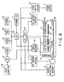
- First, the schematic construction and control of an ink jet printer, which uses a control unit for controlling a motor for use in a printer according to the present invention, will be described. The schematic construction of this ink jet printer is shown in FIG. 6.
- This ink jet printer comprises: a paper feed motor (which will be also hereinafter referred to as a PF motor) 1 for feeding a paper; a paper feed motor driver 2 for driving the paper feed motor 1; a carriage 3; a carriage motor (which will be also hereinafter referred to as a CR motor) 4; a CR motor driver 5 for driving the carriage motor 4; a DC unit 6; a pump motor 7 for controlling the suction of ink for preventing clogging; a pump motor driver 8 for driving the pump motor 7; a recording head 9, fixed to the carriage 3, for discharging ink to a printing paper 50; a head driver 10 for driving and controlling the recording head 9; a linear type encoder 11 fixed to the carriage 3; a code plate 12 which has slits in regular intervals; a rotary type encoder 13 for use in the PF motor 1; a paper detecting sensor 15 for detecting the position of the rear edge of a paper which is being printed; a CPU 16 for controlling the whole printer; a timer IC 17 for periodically generating an interruption signal to output the signal to the CPU 16; an interface part (which will be also hereinafter referred to as an IF) 19 for transmitting/receiving data to/from a host computer 18; an ASIC 20 for controlling the printing definition, the driving waveform of the recording head 9 and so forth on the basis of printing information which is fed from the host computer 18 via the IF 19; a PROM 21, RAM 22 and EEPROM 23 which are used as working and program storing regions for the ASIC 20 and the CPU 16; a platen 25 for supporting the paper 50 during print; a carrier roller 27, driven by the PF motor 1, for carrying the printing paper 50; a pulley 30 mounted on the rotating shaft of the CR motor 4; and a timing belt 31 driven by the pulley 30.
- Furthermore, the
DC unit 6 is designed to drive and control the paperfeed motor driver 2 and theCR motor driver 5 on the basis of a control command, which is fed from theCPU 16, and the outputs of theencoders paper feed motor 1 and theCR motor 4 comprises a DC motor. - The peripheral construction of the
carriage 3 of this ink jet printer is shown in FIG. 7. - The
carriage 3 is connected to thecarriage motor 4 via thetiming belt 31 and thepulley 30 to be driven so as to be guided by aguide member 32 to move in parallel to theplaten 25. Thecarriage 3 is provided with the recording head 9 on the surface facing the printing paper. The recording head 9 comprises a nozzle row for discharging a black ink and a nozzle row for discharging color inks. Each nozzle is supplied with ink from anink cartridge 34, and discharges drops of ink to the printing paper to print characters and/or images. - In a non-print region of the
carriage 3, there are provided acapping unit 35 for sealing a nozzle opening of the recording head 9 during non-print, and apump unit 36 having the pump motor 7 shown in FIG. 6. When thecarriage 3 moves from a print region to the non-print region, thecarriage 3 contacts a lever (not shown) to move thecapping unit 35 upwards to seal the recording head 9. - When the nozzle opening row of the recording head 9 is clogged with ink, or when the
cartridge 34 is exchanged or the like to force the recording head 9 to discharge ink, thepump unit 36 is operated in the sealed state of the recording head 9, to suck ink out of the nozzle opening row by a negative pressure from thepump unit 36. Thus, dust and paper powder adhering to a portion near the nozzle opening row are cleaned. Moreover, bubbles of the recording head 9, together with ink, are discharged to acap 37. - Then, the construction of the
linear type encoder 11 mounted on thecarriage 3 is shown in FIG. 8. Thisencoder 11 comprises a light emitting diode 11a, acollimator lens 11b, and adetection processing part 11c. Thedetection processing part 11c has a plurality of (four) photodiodes 11d, asignal processing circuit 11e, and two comparators 11fA and 11fB. - If a voltage Vcc is applied between both ends of the light emitting diode 11a via a resistor, light rays are emitted from the light emitting diode 11a. The light rays are collimated by the
collimator lens 11b to pass through thecode plate 12. Thecode plate 12 is provided with slits at regular intervals (e.g., every 1/180 inches (= 1/180 x 2.54 cm)). - The parallel rays passing through the
code plate 12 are incident on each of the photodiodes 11d via a fixed slit (not shown), and converted into electric signals. The electric signals outputted from the four photodiodes 11d are processed by thesignal processing circuit 11e. The signals outputted from thesignal processing circuit 11e are compared by the comparators 11fA and 11fB, and the compared results are outputted as pulses. The pulses ENC-A and ENC-B outputted from the comparators 11fA and 11fB are outputs of theencoder 11. - The phase of the pulse ENC-A is different from the phase of the pulse ENC-B by 90 degrees. The
encoder 4 is designed so that the phase of the pulse ENC-A is advanced from the pulse ENC-B by 90 degrees as shown in FIG. 9(a) when theCR motor 4 is normally rotating, i.e., when thecarriage 3 is moving a main scanning direction, and the phase of the pulse ENC-A lags behind the pulse ENC-B by 90 degrees as shown in FIG. 9(b) when theCR motor 4 is reversely rotating. One period T of the pulses corresponds to the distance between adjacent slits of the code plate 12 (e.g., 1/180 inches (= 1/180 x 2.54 cm)). This is equal to a period of time, in which thecarriage 3 moves between the adjacent slits. - On the other hand, the
rotary type encoder 13 for use in thePF motor 1 has the same construction as that of thelinear type encoder 11, except that the code plate is a rotating disk which rotates in accordance with the rotation of thePF motor 1. Furthermore, in the ink jet printer, the distance between adjacent slits of a plurality of slits provided in the code plate of theencoder 13 for use in the PF motor is 1/180 inches (1/180 x 2.54 cm). When thePF motor 1 rotates by the distance between adjacent slits, the paper is fed by 1/1440 inches (= 1/1440 x 2.54 cm). - Referring to FIG. 10, the position of the
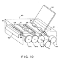
paper detecting sensor 15 shown in FIG. 6 will be described below. - In FIG. 10, the
paper 10 inserted into apaper feeding port 61 of aprinter 60 is fed into theprinter 60 by means of apaper feeding roller 64 which is driven by apaper feeding motor 63. The front edge of thepaper 50, which has been fed into theprinter 60, is detected by, e.g., an opticalpaper detecting sensor 15. Thepaper 50, the front edge of which has been detected by thepaper detecting sensor 15, is fed by means of apaper feed roller 65 and a drivenroller 66 which are driven by thePF motor 1. - Subsequently, ink drops from the recording head (not shown), which is fixed to the
carriage 3 moving along thecarriage guide member 32, to carry out a print. Then, when the paper is fed to a predetermined position, the rear edge of thepaper 50, which is currently being printed, is detected by thepaper detecting sensor 15. Then, agear 67c is driven, via agear 67b, by means of agear 67a which is driven by thePF motor 1. Thus, apaper discharging roller 68 and a drivenroller 69 are rotated to discharge the printedpaper 50 from apaper discharging port 62 to the outside. - Referring to FIGS. 11 and 12, an example of the speed control of the
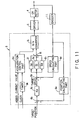
DC motor 4 using theDC unit 6 shown in FIG. 6 will be described below. - The
DC unit 6 comprises aposition calculating part 6a, asubtracter 6b, a targetspeed calculating part 6c, aspeed calculating part 6d, asubtracter 6e, aproportional element 6f, an integratingelement 6g, a differentiatingelement 6h, anadder 6i, a D/A converter 6j, atimer 6k, and anacceleration control part 6m. - The
position calculating part 6a is designed to detect the leading and trailing edges of each of the output pulses ENC-A and ENC-B of theencoder 11 to count the number of the detected edges, and to calculate the position of thecarriage 3 on the basis of the counted value. In this counting, when theCR motor 4 is normally rotating, if one edge is detected, "+1" is added, and when theCR motor 4 is reversely rotating, if one edge is detected, "-1" is added. Each of the periods of the pulses ENC-A and ENC-B is equal to the distance between adjacent slits of thecode plate 12, and the phase of the pulse ENC-A is different from the phase of the pulse ENC-B by 90 degrees. Therefore, the counted value "1" in the above described counting corresponds to 1/4 of the distance between adjacent slits of thecode plate 12. Thus, if the counted value is multiplied by 1/4 of the distance between adjacent slits, it is possible to obtain the moving amount of thecarriage 3 from a position corresponding to a counted value "0". At this time, the definition of theencoder 11 is 1/4 of the distance between adjacent slits of thecode plate 12. If the distance between adjacent slits is 1/180 inches (= 1/180 x 2.54 cm), the definition is 1/720 inches (= 1/720 x 2.54 cm). - The
subtracter 6b is designed to calculate a position deviation of the actual position of thecarriage 3, which is obtained by theposition calculating part 6a, from a target position which is fed from theCPU 16. - The target
speed calculating part 6c is designed to calculate a target speed of thecarriage 3 on the basis of the position deviation which is the output of thesubtracter 6b. This operation is carried out by multiplying the position deviation by a gain Kp. This gain Kp is determined in accordance with the position deviation. Furthermore, the value of the gain Kp may be stored in a table (not shown). - The
speed calculating part 6d is designed to calculate a speed of thecarriage 3 on the basis of the output pulses ENC-A and ENC-B of theencoder 11. This speed is obtained as follows. First, the leading and trailing edges of each of the output pulses ENC=A and ENC-B of theencoder 11 are detected, and the time interval between the edges corresponding to 1/4 of the distance between adjacent slits of thecode plate 12 is counted by, e.g., a timer counter. Assuming that the counted value is T and that the distance between adjacent slits of thecode plate 12 is λ, the speed of the carriage is λ/(4T). Furthermore, in this preferred embodiment, the speed of the carriage is obtained by counting one period of the output pulse ENC-A, e.g., the period between the leading edge and the next leading edge, by means of a timer counter. - The
subtracter 6e is designed to calculate a speed deviation of the actual speed of thecarriage 3, which is calculated by thespeed calculating part 6d, from a target speed. - The
proportional element 6f is designed to multiply the speed deviation by a constant Gp to output the multiplied result. The integratingelement 6g is designed to integrate a value which is obtained by multiplying the speed deviation by a constant Gi. The differentiatingelement 6h is designed to multiply a difference between the current speed deviation and the last speed variation by a constant Gd to output the multiplied result. Furthermore, the operations in theproportional element 6f, integratingelement 6g and differentiatingelement 6h are carried out every one period of the output pulse ENC-A of theencoder 11, i.e., in synchronism with the leading edge of the output pulse ENC-A. - The outputs of the
proportional element 6f, integratingelement 6g and differentiatingelement 6h are added by theadder 6i. Then, the added result, i.e., the driving current of theCR motor 4, is fed to the D/A converter 6j to be converted into an analog current. On the basis of the analog current, theCR motor 4 is driven by thedriver 5. - In addition, the
timer 6k and theacceleration control part 6m are used for controlling acceleration, and the PID control using theproportional element 6f, integratingelement 6g and differentiatingelement 6h is used for controlling the constant speed and deceleration during acceleration. - The
timer 6k is designed to generate a timer interruption signal every a predetermined time on the basis of a clock signal which is fed from theCPU 16. - The
acceleration control part 6m is designed to integrate a predetermined current value (e.g., 20 mA) into a target current value every time it receives the timer interruption signal, and to feed the integrated result, i.e., the target current value of theDC motor 4 during acceleration, to the D/A converter 6j. Similar to the PID control, the target current value is converted into an analog current by the D/A converter 6j. On the basis of this analog current, theCR motor 4 is driven by the driver. - The
driver 5 has, e.g., four transistors. By turning each of the transistors ON and OFF on the basis of the output of the D/A converter 6j, thedriver 5 can be selectively in (a) an operation mode in which theCR motor 4 is normally or reversely rotated, (b) a regenerative brake operation mode (a short brake operation mode, i.e., a mode in which the stopping of the CR motor is maintained), or (c) a mode in which the CR motor is intended to be stopped. - Referring to FIGS. 12 (a) and 12(b), the operation of the
DC unit 6 will be described below. - If a start-up command signal for starting the
CR motor 4 is fed from theCPU 16 to theDC unit 6 when theCR motor 4 is stopped, a start-up initial current value Io is fed from theacceleration control part 6m to the D/A converter 6j. Furthermore, this start-up initial current value Io, together with the start-up command signal, is fed from theCPU 16 to theacceleration control part 6m. Then, this current value Io is converted into an analog current by the D/A converter 6j to be fed to thedriver 5, and the CR motor is started up by the driver 5 (see FIG. 12(a), 12(b)). - After the start-up command signal is received, the
timer 6k generates a timer interruption signal every a predetermined time. Every time theacceleration control part 6m receives the timer interruption signal, theacceleration control part 6m integrates a predetermined current value (e.g., 20 mA) into the start-up initial current value Io, to feed the integrated current value to the D/A converter 6j. Then, the integrated current value is converted into an analog current by the D/A converter 6j to be fed to thedriver 5. Then, the CR motor is driven by thedriver 5 so that the value of the current supplied to theCR motor 4 is the integrated current value, so that the speed of theCR motor 4 increases (see FIG. 12(b)). Therefore, the current value supplied to the CR motor is step-wise as shown in FIG. 12(a). - Furthermore, at this time, although the PID control system also operates, the D/
A converter 6j selects and incorporates the output of theacceleration control part 6m. - The integration of the current value in the
acceleration control part 6m is carried out until the integrated current value becomes a constant current value Is. When the integrated current value becomes the predetermined value Is at time t1, theacceleration control part 6m stops the integration, and supplies the constant current value Is to the D/A converter 6j. Thus, theCR motor 4 is driven by thedriver 5 so that the value of the current supplied to theCR motor 4 becomes the current value Is (see FIG. 12(a)). - Then, in order to prevent the speed of the
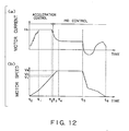
CR motor 4 from overshooting, theacceleration control part 6m controls theCR motor 4 so as to reduce the current, which is supplied to theCR motor 4, when the speed of theCR motor 4 becomes a predetermined speed V1 (see time t2). At this time, the speed of theCR motor 4 further increases. However, when the speed of theCR motor 4 reaches a predetermined speed Vc (see time t3 in FIG. 12(b)), the D/A converter 6j selects the output of the PID control system, i.e., the output of theadder 6i, to carry out the PID control. - That is, the target speed is calculated on the basis of the position deviation of the actual position, which is obtained from the output of the
encoder 11, from the target position. In addition, theproportional element 6f, integratingelement 6g and differentiatingelement 6h are operated on the basis of the speed deviation of the actual speed, which is obtained from the output of theencoder 11, from the target speed to carry out the proportional, integrating and differentiating operations. Moreover, theCR motor 4 is controlled on the basis of the sum of these calculated results. Furthermore, the above described proportional, integrating and differentiating operations are carried out in synchronism with, e.g., the leading edge of the output pulse ENC-A of theencoder 11.. Thus, the speed of theDC motor 4 is controlled so as to be a desired speed Ve. Furthermore, the predetermined speed Vc is preferably a value of 70 % to 80 % of the desired speed Ve. - Since the speed of the
DC motor 4 is the desired speed Ve after time t4, a printing processing can be carried out. When the printing processing is completed and when thecarriage 3 reaches the target position (see time t5. in FIG. 12 (b)), theDC motor 4 is decelerated to be stopped at time t6. - The construction of the first preferred embodiment of a control unit for controlling a motor for use in a printer according to the present invention is shown in FIG. 1. The control unit in this preferred embodiment is used for controlling a
carriage motor 4 comprising a DC motor for use in an ink jet printer, and comprises aDC unit 80. TheDC unit 80 includes an averagespeed measuring part 90, which is substituted for thespeed calculating part 6d of theDC unit 6 shown in FIG. 11, and asubtracter 96 which is newly provided. - The average
speed measuring part 90 comprises aspeed calculating part 91, amemory 92, and an averagespeed calculating part 93. Thespeed calculating part 91 has the same construction as that of thespeed calculating part 6d shown in FIG. 11. Thespeed calculating part 91 is designed to calculate a speed of theCR motor 4, i.e., a speed of thecarriage 3, on the basis of the output of theencoder 11. - This operation is carried out in synchronism with the leading edge of the output pulse ENC-A of the
encoder 11. - The
memory 92 is designed to store therein n speed data from the last calculated result to a calculated result of n (n ≧ 1) before, which have been calculated by thespeed calculating part 91. After the averagespeed calculating part 93 reads n speed data, thememory 92 is designed to store therein the current speed which is calculated by thespeed calculating part 91 in place of the calculated speed of n before. - The average
speed calculating part 93 is designed to calculate an average of two speed data of the current speed data, which are calculated by thespeed calculating part 91, and speed data of n before, which have been stored in thememory 92. - The
subtracter 6e is designed to calculate a speed deviation of the current speed, which is calculated by thespeed calculating part 91, from a target speed, which is the output of the targetspeed calculating part 6c, to transmit the calculated speed deviation to the integratingelement 6g. - The
subtracter 96 is designed to calculate a speed deviation of the average speed, which is the output of the averagespeed calculating part 93, from the target speed, which is the output of the targetspeed calculating part 6c, to transmit the calculated speed deviation to theproportional element 6f and the differentiatingelement 6h. - The
proportional element 6f is designed to multiply the output of thesubtracter 96 by a constant Gp to transmit the multiplied result to theadder 6i. The integratingelement 6g is designed to integrate a value, which has been obtained by multiplying the output of the subtracter 6e by a constant Gi, to transmit the integrated result to theadder 6i. The differentiatingelement 6h is designed to multiply a difference between the current speed deviation and the last speed deviation by a constant Gd to transmit the multiplied result to theadder 6i. Furthermore, the operations in theproportional element 6f, integratingelement 6g and differentiatingelement 6h are carried out in synchronism with the leading edge of the output pulse ENC-A of theencoder 11. - The outputs of the
proportional element 6f, integratingelement 6g and differentiatingelement 6h are added up by theadder 6i. Then, the added result, i.e., the current for driving theCR motor 4 which causes the above described speed deviation to be zero, is fed to the D/A converter 6j to be converted an analog current. On the basis of this analog current, theCR motor 4 is driven by thedriver 5. - In this preferred embodiment, the number n used for calculating the average speed approximates to Tv/ (2tv) assuming that the period of the fluctuation in speed of the
CR motor 4 is Tv and that the period of the operation of the speed in thespeed calculating part 91 is tv. By thus causing the number n to approximate to Tv/(2tv), the fluctuation in speed of theCR motor 4 can be suppressed. - Referring to FIGS. 2 and 3, this will be described. In this preferred embodiment, it is assumed that the number of poles of the
CR motor 4 is 5, that the effective diameter length (i.e., the pitch circle length) L of thepulley 30, mounted on the rotating shaft of theCR motor 4, for driving thetiming belt 31 is 26 mm, and that the distance λ between adjacent slits of thecode plate 12 of theencoder 11 is 1/180 inches (= 0.14 mm). Then, the fluctuation in speed of theCR motor 4 occurs 10 times every one rotation, i.e., 10 times while thecarriage 3 moves by 26 mm, so that the period Tv of the fluctuation in speed is equal to a period of time, in which thecarriage 3 moves by 2.6 mm (= 26 mm / (2×5)). - On the other hand, the operation period tv of the
speed calculating part 91 is equal to the period of the output pulse ENC-A of theencoder 11, i.e., a period of time, in which thecarriage 3 moves by the distance between adjacent slits (= 0.14 mm) of thecode plate 12. - Therefore, in one period of the fluctuation in speed of the
CR motor 4, Tv/tv = 18.4 (= 2.6 mm / 0.14 mm) speed operations are carried out by thespeed calculating part 91. - In such conditions, assuming that the speed of the rotating shaft of the
CR motor 4 fluctuates as a sinusoidal wave about a predetermined speed Ve and that the number n used for calculating the average speed by the averagespeed calculating part 93 is a parameter, the state of the output of the average speed calculating part in this preferred embodiment is shown in FIG. 2. Furthermore, in FIG. 2, only the fluctuating part in speed is normalized. - In FIG. 2, a graph g1 shows the state of the fluctuation in speed when n = 0, i.e., when the output of the average
speed calculating part 93 is coincident with the output of thespeed calculating part 91, and a graph g2 shows the state of the fluctuation in speed when n = 7, i.e., the fluctuation in average speed of the current calculated speed and a calculated speed of 7 before. In addition, a graph g3 shows the state of the fluctuation in speed when n = 8, i.e., the fluctuation in average speed of the current calculated speed and a calculated speed of 8 before, and a graph g4 shows the state of the fluctuation in speed when n = 9, i.e., the fluctuation in average speed of the current calculated speed and a calculated speed of 9 before. Moreover, a graph g5 shows the state of the fluctuation in speed when n = 10, i.e., the fluctuation in average speed of the current calculated speed and a calculated speed of 10 before, and a graph g6 shows the state of the fluctuation in speed when n = 11, i.e., the fluctuation in average speed of the current calculated speed and a calculated speed of 11 before. - As can be seen from the calculated results shown in FIG. 2, when n = 9, i.e., when n approximates to Tv/(2tv) (= 9.2), the fluctuation in speed is smallest. It is considered that the reason for this is that if the product ntv of the operation period tv of the
speed calculating part 91 and the number n is about half of the period Tv of the fluctuation in speed of theCR motor 4, the average speed calculated by the averagespeed calculating part 93 approximates to zero as shown in FIG. 3, so that the fluctuation in speed decreases. - Therefore, it is possible to suppress the fluctuation in speed if the number n used for calculating the average speed meets the following expression.

- Furthermore, in practice, as shown in FIG. 4, the
timing belt 31 is stretched at a tension between thepulley 30, which is driven by theCR motor 4, and the drivenwheel 30a which is driven by thepulley 30, so that the fluctuation in speed of theCR motor 4 is lately transmitted to thecarriage 3. Therefore, as can be seen from FIG. 2, it is considered that the use of n = 10, in which the phase is advanced, is more effective in the suppression of the fluctuation in speed of theCR motor 4 although the fluctuation in speed is slightly greater than that when n = 9. - Therefore, assuming that the distance between adjacent slits of the
code plate 12 of theencoder 11 is λ, that the pitch circle length (the effective diameter length) of thepulley 30 is L, and that the number of phases of theCR motor 4 is p, then, the number n used for calculating the average speed preferably meets the following expression.
CR motor 4 is Tv and that the operation period of thespeed calculating part 91 is tv, the following expression is satisfied.
- As described above, according to this preferred embodiment, it is possible to suppress the fluctuation in speed of the CR motor.
- Furthermore, while the speed deviation serving as the deviation of the average speed from the target speed has been inputted to the
proportional element 6f and the differentiatingelement 6f in this preferred embodiment, the same effects can be obtained if the speed deviation is inputted to only the differentiatingelement 6h and if the speed deviation of the output of thespeed calculating part 91 from the target speed is inputted to theproportional element 6f and the integratingelement 6f. In addition, the same effects can be obtained if the speed deviation of the average speed from the target speed is inputted to all of theproportional element 6f, the integratingelement 6g and the differentiatingelement 6h. - Furthermore, while the
position calculating part 6a has counted the leading and trailing edges of the output pulses ENC-A and ENC-B of theencoder 11 to multiply the counted value by the distance between adjacent slits of thecode plate 12 of theencoder 11, the leading and trailing edges of the output pulses ENC-A and ENC-B may be counted without the multiplication by the distance between adjacent slits, to be outputted. In this case, the target position is also expressed by the number of pulses, and the output of thespeed calculating part 91 is the inverse number of the period of the output pulse ENC-A of theencoder 11. In addition, the averagespeed calculating part 93 calculates an average value of the inverse number of the period of the output pulse ENC-A to output the calculated average value. - In addition, while the average
speed calculating part 93 has calculated the average speed of the current calculated speed and the calculated speed of n before in the above described first preferred embodiment, the average value (the average speed) of k+1 calculated speed data from the current calculated speed to a calculated speed of k (n > k ≧ 1) before and k+1 calculated speed data from a calculated speed of n before and a calculated speed of n+k before may be obtained. In this case, n+k calculated speed data from the last calculated speed to the calculated speed of n+k before are stored in thememory 92. With this construction, it is possible to suppress the influence of noises. - In addition, the average
speed calculating part 93 may be designed to obtain an average value of m (n-1 ≧ m ≧ 2) calculated speed data, which are selected from n calculated speed data from the current calculated speed to a calculated speed of n-1 before and which include the current calculated speed, and m calculated speed data which are selected from n calculated speed data from a calculated speed of n before to a calculated speed of 2n-1 and which correspond to the m calculated speed data. The calculated speed data corresponding to the current calculated speed data are the calculated speed data of n before, and the calculated speed data corresponding to the calculated speed data of k (n-1 ≧ k ≧ 1) before are the calculated speed data of n+k before. - In addition, in the above described preferred embodiment, while the value approximating to Tv / (2tv) = L / (4pλ) = πD / (4pλ) has been selected as the number n used for calculating the average speed assuming that the number of phases of the
CR motor 4 is p, that the effective length of thepulley 30 is L (= πD (D is a pitch circle diameter)), that the period of the fluctuation in speed of theCR motor 4 is Tv, that the operation period of thespeed calculating part 91 is tv and that the distance between adjacent slits of theencoder 11 is λ, n may be fixed to a predetermined value, and the pitch circle diameter D may be a value meeting the above described relationship. - Furthermore, in the ink jet printer, the speed of the
carriage 3 fluctuates under the influence of (a) the fluctuation in speed of theCR motor 4, (b) the fluctuation in speed of thetiming belt 31, and (c) the fluctuation in speed of the pulley. Therefore, it is not only required to suppress the fluctuation in speed of theCR motor 4, but it is also required to suppress the fluctuation in speed due to other factors. In the following second preferred embodiment, the fact that the fluctuation in speed due to other factors can be suppressed will be described below. - The construction of the second preferred embodiment of a control unit for controlling a motor for use in a printer according to the present invention is shown in FIG. 5. The control unit in this second preferred embodiment is used for controlling the speed of a CR motor of an ink jet printer. In this preferred embodiment, a
DC unit 80A is substituted for theDC unit 80 of the control unit in the first preferred embodiment shown in FIG. 1. TheDC unit 80A has an averagespeed measuring part 90A, asubtracter 97 and a differentiatingelement 98 which are newly added to theDC unit 80 shown in FIG. 1. - The average
speed measuring part 90A has substantially the same construction as that of the averagespeed measuring part 90, and comprises aspeed calculating part 91A, amemory 92A and an averagespeed calculating part 93A. - The
speed calculating part 91A has the same construction as that of thespeed calculating part 91, and is designed to calculate the speed of theCR motor 4, i.e., the speed of thecarriage 3, on the basis of the output pulse ENC-A of theencoder 11. This operation is carried out in synchronism with the leading edge of the output pulse ENC-A of theencoder 11. - The
memory 92A is designed to store therein m speed data from the last calculated result to the calculated result of m (m ≧ 2) before, which are calculated by thespeed calculating part 91A. After the averagespeed calculating part 93A reads data of m before, thememory 92A is designed to store therein the current calculated speed, which is calculated by thespeed calculating part 91A, in place of the calculated speed of m before. - The average
speed calculating part 93A is designed to calculate an average value (an average speed) of the current speed data, which are calculated by thespeed calculating part 91A, and the calculated speed of m before, to transmit the calculated result to thesubtracter 97. - The
subtracter 97 is designed to calculate a speed deviation of the average speed, which is the output of the averagespeed calculating part 93A, from the target speed which is the output of the target speed calculating means 6c. - The differentiating
element 98 is designed to multiply the difference between the current speed deviation and the last speed deviation by a constant GdA, to transmit the multiplied result to theadder 6i. - Then, the sum of the outputs of the
proportional element 6f, integratingelement 6g, differentiatingelement 6h and differentiatingelement 98 is calculated by theadder 6i. The output of theadder 6i, i.e., the driving current for theCR motor 4 which causes the speed deviation to be zero, is fed to the D/A converter 6j to be converted an analog current. On the basis of this analog current, theCR motor 4 is driven by thedriver 5. - In this preferred embodiment, the number m used for calculating the average speed approximates to TvA/(2tvA) assuming that the period of the fluctuation in speed to be suppressed other than the fluctuation in speed of the
CR motor 4 is TvA and that the operation period in thespeed calculating part 91A is tvA. - As described above, the control unit in this second preferred embodiment can suppress the fluctuation in speed of the
CR motor 4, and can also suppress the fluctuation in speed due to other factors. - Furthermore, in the second preferred embodiment, the operation period of the
speed calculating part 91A has been equal to the period of the output pulse ENC-A of theencoder 11. However, when the period of the fluctuation in speed to be suppressed is shorter than the period of the fluctuation in speed of the CR motor, the operation of thespeed calculating part 91A is preferably carried out in synchronism with the leading and trailing edges of each of the output pulses ENC-A and ENC-B of the encoder, or on the basis of the output pulse of a higher definition encoder. - In addition, in the second preferred embodiment, the average
speed calculating part 93A has calculated the average speed of the current calculated speed and the calculated speed of m before. However, the average value (the average speed) of k+1 calculated speed data from the current calculated speed to the calculated speed of k (m > k ≧ 1) before and k+1 calculated speed data from the calculated speed of m before to the calculated speed of m+k before may be obtained. In this case, thememory 92 stores therein m+k calculated speed data from the last calculated speed to the calculated speed of m+k before. - Furthermore, the DC motor has been described in the above described first and second preferred embodiments, the present invention can also be applied to an AC motor.
- Referring to FIG. 14, the third preferred embodiment of the present invention will be described below. This third preferred embodiment relates to a method for controlling a motor for use in a printer, and the control procedure thereof is shown in FIG. 14.
- First, the speed of a motor for use in a printer, e.g., the speed of a carriage motor, is detected in a predetermined period tv to be stored (see step F1 in FIG. 14) . Then, an average speed is calculated using at least the current detected speed and a detected speed which has been detected n (n ≧ 2), which corresponds to substantially half period in the fluctuation in speed of the motor, before the timing in detecting the current detected speed (see step F2 in FIG. 14). Subsequently, the speed of the motor is controlled on the basis of the speed deviation of the average speed from the target speed (see step F3 in FIG. 14).
- According to the above described control method in this preferred embodiment, the influence of the fluctuation in speed is removed from the calculated average speed, so that the fluctuation in speed can be suppressed by controlling the speed of the motor on the basis of the speed deviation of the average speed from the target speed.
- Furthermore, at the step of calculating the average speed, the average speed of k+1 detected speeds from the current detected speed to the detected speed of k (n > k≧ 0) before and k+1 detected speeds from the detected speed of n before to the detected speed of n+k before may be obtained.
- In addition, at the step of controlling the speed of the motor, the motor may be controlled on the basis of the sum of the speed deviation and the output of the differentiating element which is operated on the basis of the speed deviation.
- Referring to FIGS. 15 and 16, the fourth preferred embodiment of the present invention will be described below. This preferred embodiment relates to a storage medium, in which a control program for controlling a motor for use in a printer has been stored. FIGS. 15 and 16 are a perspective view and block diagram showing an example of a
computer system 130 which uses a storage medium, in which a print control program in this preferred embodiment has been recorded. - In FIG. 15, the
computer system 130 comprises acomputer body 130 including a CPU, adisplay unit 132, such as a CRT, aninput unit 133, such as a keyboard or mouse, and aprinter 134 for carrying out a print. - As shown in FIG. 16, the
computer body 131 comprises aninternal memory 135 of a RAM, and a built-in orexterior memory unit 136. As thememory unit 136, a flexible or floppy disk (FD) drive 137, a CD-ROM drive 138 and a hard disk drive (HD)unit 139 are mounted. As shown in FIG. 15, a flexible disk or floppy disk (FD) 141 which is inserted into a slot of the FD drive 137 to be used, a CD-ROM 142 which is used for the CD-ROM drive 138, or the like is used as astorage medium 140 for use in thememory unit 136. - As shown in FIGS. 15 and 16, it is considered that the
FD 141 or the CD-ROM 142 is used as the storage medium for use in a typical computer system. However, since this preferred embodiment relates to a control program for controlling a motor for use in theprinter 134, the control program of the present invention may be recorded in, e.g., aROM chip 143 serving as a nonvolatile memory which is built in theprinter 134. Of course, the storage medium may be any one of FDs, CD-ROMs, MOs (Magneto-Optical) disks, DVDs (Digital Versatile Disks), other optical recording disks, card memories, and magnetic tapes. - The
storage medium 140 in this preferred embodiment is designed to carry out a control procedure including steps. F1 through F3 shown in FIG. 14. That is, thestorage medium 140 in this preferred embodiment may carry out the steps of detecting the speed of a motor in a predetermined period tv, calculating an average speed using at least the current detected speed and a detected speed which has been detected n (n ≧ 2), which corresponds to substantially half period in the fluctuation in speed of the motor, before the timing in detecting the current detected speed, and controlling the speed of the motor on the basis of a speed deviation of the average speed from the target speed. - As described above, according to the present invention, it is possible to suppress the fluctuation in speed of a motor for use in a printer.
- While the present invention has been disclosed in terms of the preferred embodiment in order to facilitate better understanding thereof, it should be appreciated that the invention can be embodied in various ways without departing from the principle of the invention. Therefore, the invention should be understood to include all possible embodiments and modification to the shown embodiments which can be embodied without departing from the principle of the invention as set forth in the appended claims.
- Reference signs in the claims are intended for better understanding and shall not limit the scope.
Claims (18)
- A control unit for controlling a motor in a printer, said control unit comprising:a speed detecting part (11, 91) for detecting a speed of said motor in a predetermined period tv;an average speed calculating part (93) for calculating an average speed based on, from said speed detecting part, a current detected speed and a previously detected speed which has been detected n (≧ 2) periods tv before a detecting of said current speed corresponding to a substantially half period of a fluctuation in speed of said motor Tv, anda speed control part (6f, 6h) for controlling the speed of said motor on the basis of a speed deviation of said average speed from a target speed of said motor.
- A control unit for controlling a motor in a printer, as set forth in claim 1, wherein assuming that the period of the fluctuation in speed of said motor is Tv, the number n used for calculating said average speed meets the following expression.

- A control unit for controlling a motor in a printer, as set forth in claim 2, wherein said average speed calculating part calculates an average speed of k+1 detected speeds from the current detected speed to a detected speed of k (n > k ≧ 0) before, and k+1 detected speeds from a detected speed of n before to a detected speed of k+1 before.
- A control unit for controlling a motor in a printer, as set forth in claim 3, wherein said speed control part has a differentiating element (6d) which operates on the basis of said speed deviation of said average speed from said target speed.
- A control unit for controlling a motor in a printer, as set forth in claim 4, wherein said speed control part has a proportional element (6f) which operates on the basis of said speed deviation of said average speed from said target speed.
- A control unit for controlling a motor in a printer, as set forth in claim 5, wherein said speed detecting part comprises an encoder (11) for generating an output pulse in accordance with the rotation of said motor, and a speed calculating part (91) for calculating the speed of said motor in a period of said output pulse on the basis of said output pulse of said encoder.
- A control unit for controlling a motor in a printer, as set forth in claim 6, wherein said motor is a carriage motor for use in an ink jet printer, and said encoder generates said output pulse in accordance with the movement of a carriage driven by said carriage motor via a pulley, which is mounted of the rotating shaft of said carriage motor, and via a timing belt which is driven by said pulley.
- A control unit for controlling a motor in a printer, as set forth in claim 7, wherein assuming that the distance between adjacent slits of a code plate of said encoder is λ, that a pitch circle length of said pulley is L and that the number of phases of said motor is p, said n meets the following expression.

- A control unit for controlling a motor in a printer, as set forth in claim 7 or 8, wherein said speed control part further comprises:a second speed calculating part (91A) for calculating the speed of said motor in a second predetermined period on the basis of said output pulse of said encoder;a second average speed calculating part (93A) for calculating said average speed using at least the current calculated speed, which is calculated by said second speed calculating part, and a calculated speed which has been m (m ≧ 2) before; anda second differentiating element (98) which operates on the basis of a speed deviation of the output of said second average speed calculating part from said target speed.
- A control unit for controlling a motor in a printer, as set forth in any one of claims 1 to 9, wherein said motor is a DC motor.
- A method for controlling a motor in a printer, said method comprising the steps of:detecting a speed of said motor in a predetermined period tv;calculating an average speed based on, from said detecting, a current detected speed and on a previously detected speed which has been detected n (≧ 2) periods tv before said detecting of said current speed corresponding to a substantially half period of a fluctuation in speed of said motor Tv, andcontrolling the speed of said motor on the basis of a speed deviation of said average speed from a target speed of said motor.
- A method for controlling a motor in a printer, as set forth in claim 11, wherein assuming that the period of the fluctuation in speed of said motor is Tv, the number n used for calculating said average speed meets the following expression.

- A method for controlling a motor in a printer,as set forth in claim 12, wherein said step of calculating said average speed calculates an average speed of k+1 detected speeds from the current detected speed to a detected speed of k (n > k ≧ 0) before, and k+1 detected speeds from a detected speed of n before to a detected speed of k+1 before.
- A method for controlling a motor in a printer,as set forth in claim 13, wherein said step of controlling the speed of said motor controls the speed of said motor on the basis of the sum of said speed deviation and the output of a differentiating element which operates on the basis of said speed deviation.
- A method for controlling a motor in a printer, as set forth in claim 14, wherein said step of detecting the speed of said motor includes a step of calculating the speed of said motor in a period of an output pulse of an encoder, which generates said output pulse in accordance with the rotation of said motor, on the basis of said output pulse of said encoder.
- A method for controlling a motor in a printer, as set forth in claim 15, wherein said motor is a carriage motor for use in an ink jet printer.
- A method for controlling a motor in a printer, as set forth in any one of claims 11 to 16, wherein said motor is a DC motor.
- A computer-readable storage medium storing control program code for controlling a motor in a printer, comprising:first program code means for detecting the speed of said motor in a predetermined period tv;second program code means for calculating an average speed using at least a current detected speed and a detected speed which has been detected n (≧ 2) periods tv before a time when said current speed is detected, corresponding to a substantially half period of a fluctuation in speed of said motor Tv, andthird program code means for controlling the speed of said motor on the basis of a speed deviation of said average speed from a target speed of said motor.
Applications Claiming Priority (4)
| Application Number | Priority Date | Filing Date | Title |
|---|---|---|---|
| JP21107699 | 1999-07-26 | ||
| JP21107699 | 1999-07-26 | ||
| JP2000141661A JP3859115B2 (en) | 1999-07-26 | 2000-05-15 | Printer motor control apparatus, control method, and recording medium recording control program |
| JP2000141661 | 2000-05-15 |
Publications (3)
| Publication Number | Publication Date |
|---|---|
| EP1072425A2 EP1072425A2 (en) | 2001-01-31 |
| EP1072425A3 EP1072425A3 (en) | 2001-02-07 |
| EP1072425B1 true EP1072425B1 (en) | 2006-03-29 |
Family
ID=26518419
Family Applications (1)
| Application Number | Title | Priority Date | Filing Date |
|---|---|---|---|
| EP00306297A Expired - Lifetime EP1072425B1 (en) | 1999-07-26 | 2000-07-24 | Control unit and method for controlling motor for use in printer and storage medium storing control program |
Country Status (6)
| Country | Link |
|---|---|
| US (3) | US6528962B1 (en) |
| EP (1) | EP1072425B1 (en) |
| JP (1) | JP3859115B2 (en) |
| CN (1) | CN1120093C (en) |
| AT (1) | ATE321669T1 (en) |
| DE (1) | DE60026942T2 (en) |
Families Citing this family (17)
| Publication number | Priority date | Publication date | Assignee | Title |
|---|---|---|---|---|
| JP3832712B2 (en) * | 2000-09-21 | 2006-10-11 | セイコーエプソン株式会社 | PRINT CONTROL DEVICE, CONTROL METHOD, AND RECORDING MEDIUM CONTAINING PRINT CONTROL PROGRAM |
| JP3687606B2 (en) | 2001-12-20 | 2005-08-24 | ブラザー工業株式会社 | Motor control method and apparatus |
| US7026775B2 (en) * | 2001-12-20 | 2006-04-11 | Brother Kogyo Kabushiki Kaisha | Method and apparatus for controlling speed of moving body |
| JP2004172854A (en) | 2002-11-19 | 2004-06-17 | Seiko Epson Corp | Image sensor controller, electronic device, and image sensor control method |
| JP2004170614A (en) | 2002-11-19 | 2004-06-17 | Seiko Epson Corp | Electronics |
| JP2004172861A (en) | 2002-11-19 | 2004-06-17 | Seiko Epson Corp | Electronic device controller and electronic device control method |
| KR100777450B1 (en) | 2005-05-28 | 2007-11-21 | 삼성전자주식회사 | Encoder speed correction method and device |
| US8021469B2 (en) | 2005-07-14 | 2011-09-20 | Access Business Group International Llc | Control methods for an air treatment system |
| JP4994768B2 (en) * | 2005-12-09 | 2012-08-08 | キヤノン株式会社 | Image forming apparatus |
| JP2007182265A (en) * | 2005-12-29 | 2007-07-19 | Brother Ind Ltd | Sheet transport device |
| JP4781127B2 (en) * | 2006-02-24 | 2011-09-28 | オムロンオートモーティブエレクトロニクス株式会社 | Electric motor control device |
| JP4483812B2 (en) | 2006-03-24 | 2010-06-16 | セイコーエプソン株式会社 | Printing apparatus, stick-slip handling method, program, and printing system |
| US7898207B2 (en) * | 2007-12-04 | 2011-03-01 | Pitney Bowes Inc. | Method for controlling a DC motor |
| JP5371419B2 (en) * | 2008-12-26 | 2013-12-18 | キヤノン株式会社 | Method for controlling motor in equipment |
| JP5610838B2 (en) * | 2010-05-11 | 2014-10-22 | キヤノン株式会社 | Equipment with motor |
| CN107718912A (en) * | 2017-11-21 | 2018-02-23 | 珠海冰河电子技术有限公司 | A kind of printer speed control method and device |
| CN114337404B (en) * | 2021-12-30 | 2024-06-18 | 海信(广东)空调有限公司 | DC motor control method, air conditioner and computer readable storage medium |
Family Cites Families (12)
| Publication number | Priority date | Publication date | Assignee | Title |
|---|---|---|---|---|
| US3863118A (en) * | 1973-01-26 | 1975-01-28 | Warner Electric Brake & Clutch | Closed-loop speed control for step motors |
| US4103216A (en) * | 1976-05-28 | 1978-07-25 | Tally Corporation | Stepping motor closed loop constant velocity control system |
| US4490796A (en) * | 1981-10-16 | 1984-12-25 | International Business Machines Corporation | Print head motor control system using analog and digital feedback |
| JPS60118077A (en) * | 1983-11-29 | 1985-06-25 | Oki Electric Ind Co Ltd | Spacing speed controlling method of printer |
| US4775945A (en) * | 1985-12-11 | 1988-10-04 | International Business Machines Corporation | Print head motor control system with automatic drive parameter calculations |
| JPH07115521B2 (en) * | 1988-11-30 | 1995-12-13 | 沖電気工業株式会社 | DC motor speed controller |
| JP3230364B2 (en) * | 1994-03-03 | 2001-11-19 | 株式会社明電舎 | Speed estimation calculation processing method in speed control system |
| JP3296527B2 (en) * | 1994-08-05 | 2002-07-02 | 株式会社安川電機 | Motor speed control device |
| JPH09202014A (en) * | 1996-01-24 | 1997-08-05 | Brother Ind Ltd | Printer |
| EP0807528B1 (en) * | 1996-05-15 | 2001-12-12 | Océ-Technologies B.V. | Method and system for detecting the position of a carriage |
| JP3281561B2 (en) * | 1996-12-25 | 2002-05-13 | シャープ株式会社 | Motor speed control device |
| US6111384A (en) * | 1998-05-26 | 2000-08-29 | Eastman Kodak Company | Method for controlling motor speed |
-
2000
- 2000-05-15 JP JP2000141661A patent/JP3859115B2/en not_active Expired - Fee Related
- 2000-07-24 EP EP00306297A patent/EP1072425B1/en not_active Expired - Lifetime
- 2000-07-24 AT AT00306297T patent/ATE321669T1/en not_active IP Right Cessation
- 2000-07-24 DE DE60026942T patent/DE60026942T2/en not_active Expired - Lifetime
- 2000-07-26 CN CN00121956A patent/CN1120093C/en not_active Expired - Fee Related
- 2000-07-26 US US09/625,994 patent/US6528962B1/en not_active Expired - Lifetime
-
2002
- 2002-09-25 US US10/253,498 patent/US20030025471A1/en not_active Abandoned
-
2005
- 2005-03-09 US US11/074,761 patent/US20050146300A1/en not_active Abandoned
Also Published As
| Publication number | Publication date |
|---|---|
| US6528962B1 (en) | 2003-03-04 |
| EP1072425A2 (en) | 2001-01-31 |
| ATE321669T1 (en) | 2006-04-15 |
| JP2001103778A (en) | 2001-04-13 |
| CN1120093C (en) | 2003-09-03 |
| CN1282015A (en) | 2001-01-31 |
| DE60026942T2 (en) | 2006-08-24 |
| DE60026942D1 (en) | 2006-05-18 |
| US20030025471A1 (en) | 2003-02-06 |
| US20050146300A1 (en) | 2005-07-07 |
| EP1072425A3 (en) | 2001-02-07 |
| JP3859115B2 (en) | 2006-12-20 |
Similar Documents
| Publication | Publication Date | Title |
|---|---|---|
| US6747429B2 (en) | Print control system, print control method, and recording medium having recorded print control program | |
| EP1072425B1 (en) | Control unit and method for controlling motor for use in printer and storage medium storing control program | |
| US7712857B2 (en) | Printing apparatus, printing method, program, storage medium, and computer system | |
| EP1602504B1 (en) | Motor control device and motor control method | |
| EP1088674B1 (en) | Control unit and method for controlling motor for use in printer, and storage medium storing control program | |
| EP1124320B1 (en) | Motor control method and motor control apparatus | |
| US6390698B1 (en) | Apparatus and method of detecting home position of carriage and storage medium storing home position detection program | |
| JP3832174B2 (en) | Motor control device and control method | |
| US6967729B1 (en) | Control unit and method for controlling motor for use in printer, and storage medium storing control program | |
| JP3570617B2 (en) | DC motor control device and control method | |
| JP2001251878A (en) | Motor control device and control method | |
| JP3705061B2 (en) | MOTOR CONTROL DEVICE, ITS CONTROL METHOD, AND RECORDING MEDIUM CONTAINING MOTOR CONTROL PROGRAM | |
| JP3893853B2 (en) | Printer motor control apparatus and control method | |
| JP3871181B2 (en) | PRINT CONTROL DEVICE, CONTROL METHOD, AND RECORDING MEDIUM CONTAINING PRINT CONTROL PROGRAM | |
| JP2001224189A (en) | Motor control method and control device | |
| JP3849908B2 (en) | Print control apparatus and print control method | |
| JP4432055B2 (en) | Printer motor control apparatus and control method | |
| JP2005200222A (en) | PRINT CONTROL DEVICE, CONTROL METHOD, AND RECORDING MEDIUM CONTAINING PRINT CONTROL PROGRAM | |
| JP2001315395A (en) | PRINT CONTROL DEVICE, PRINT CONTROL METHOD, AND RECORDING MEDIUM CONTAINING PRINT CONTROL PROGRAM | |
| JP2001078475A (en) | Motor control device and control method | |
| JP2002283559A (en) | PRINT CONTROL DEVICE, PRINT CONTROL METHOD, AND RECORDING MEDIUM CONTAINING PRINT CONTROL PROGRAM |
Legal Events
| Date | Code | Title | Description |
|---|---|---|---|
| PUAI | Public reference made under article 153(3) epc to a published international application that has entered the european phase |
Free format text: ORIGINAL CODE: 0009012 |
|
| PUAL | Search report despatched |
Free format text: ORIGINAL CODE: 0009013 |
|
| AK | Designated contracting states |
Kind code of ref document: A2 Designated state(s): AT BE CH CY DE DK ES FI FR GB GR IE IT LI LU MC NL PT SE |
|
| AX | Request for extension of the european patent |
Free format text: AL;LT;LV;MK;RO;SI |
|
| AK | Designated contracting states |
Kind code of ref document: A3 Designated state(s): AT BE CH CY DE DK ES FI FR GB GR IE IT LI LU MC NL PT SE |
|
| AX | Request for extension of the european patent |
Free format text: AL;LT;LV;MK;RO;SI |
|
| 17P | Request for examination filed |
Effective date: 20010614 |
|
| AKX | Designation fees paid |
Free format text: AT BE CH CY DE DK ES FI FR GB GR IE IT LI LU MC NL PT SE |
|
| 17Q | First examination report despatched |
Effective date: 20040907 |
|
| GRAP | Despatch of communication of intention to grant a patent |
Free format text: ORIGINAL CODE: EPIDOSNIGR1 |
|
| GRAS | Grant fee paid |
Free format text: ORIGINAL CODE: EPIDOSNIGR3 |
|
| GRAA | (expected) grant |
Free format text: ORIGINAL CODE: 0009210 |
|
| AK | Designated contracting states |
Kind code of ref document: B1 Designated state(s): AT BE CH CY DE DK ES FI FR GB GR IE IT LI LU MC NL PT SE |
|
| PG25 | Lapsed in a contracting state [announced via postgrant information from national office to epo] |
Ref country code: IT Free format text: LAPSE BECAUSE OF FAILURE TO SUBMIT A TRANSLATION OF THE DESCRIPTION OR TO PAY THE FEE WITHIN THE PRE;WARNING: LAPSES OF ITALIAN PATENTS WITH EFFECTIVE DATE BEFORE 2007 MAY HAVE OCCURRED AT ANY TIME BEFORE 2007. THE CORRECT EFFECTIVE DATE MAY BE DIFFERENT FROM THE ONE RECORDED.SCRIBED TIME-LIMIT Effective date: 20060329 Ref country code: AT Free format text: LAPSE BECAUSE OF FAILURE TO SUBMIT A TRANSLATION OF THE DESCRIPTION OR TO PAY THE FEE WITHIN THE PRESCRIBED TIME-LIMIT Effective date: 20060329 Ref country code: BE Free format text: LAPSE BECAUSE OF FAILURE TO SUBMIT A TRANSLATION OF THE DESCRIPTION OR TO PAY THE FEE WITHIN THE PRESCRIBED TIME-LIMIT Effective date: 20060329 Ref country code: CH Free format text: LAPSE BECAUSE OF FAILURE TO SUBMIT A TRANSLATION OF THE DESCRIPTION OR TO PAY THE FEE WITHIN THE PRESCRIBED TIME-LIMIT Effective date: 20060329 Ref country code: LI Free format text: LAPSE BECAUSE OF FAILURE TO SUBMIT A TRANSLATION OF THE DESCRIPTION OR TO PAY THE FEE WITHIN THE PRESCRIBED TIME-LIMIT Effective date: 20060329 Ref country code: NL Free format text: LAPSE BECAUSE OF FAILURE TO SUBMIT A TRANSLATION OF THE DESCRIPTION OR TO PAY THE FEE WITHIN THE PRESCRIBED TIME-LIMIT Effective date: 20060329 |
|
| REG | Reference to a national code |
Ref country code: GB Ref legal event code: FG4D |
|
| REG | Reference to a national code |
Ref country code: CH Ref legal event code: EP |
|
| REG | Reference to a national code |
Ref country code: IE Ref legal event code: FG4D |
|
| REF | Corresponds to: |
Ref document number: 60026942 Country of ref document: DE Date of ref document: 20060518 Kind code of ref document: P |
|
| PG25 | Lapsed in a contracting state [announced via postgrant information from national office to epo] |
Ref country code: SE Free format text: LAPSE BECAUSE OF FAILURE TO SUBMIT A TRANSLATION OF THE DESCRIPTION OR TO PAY THE FEE WITHIN THE PRESCRIBED TIME-LIMIT Effective date: 20060629 Ref country code: DK Free format text: LAPSE BECAUSE OF FAILURE TO SUBMIT A TRANSLATION OF THE DESCRIPTION OR TO PAY THE FEE WITHIN THE PRESCRIBED TIME-LIMIT Effective date: 20060629 |
|
| PG25 | Lapsed in a contracting state [announced via postgrant information from national office to epo] |
Ref country code: ES Free format text: LAPSE BECAUSE OF FAILURE TO SUBMIT A TRANSLATION OF THE DESCRIPTION OR TO PAY THE FEE WITHIN THE PRESCRIBED TIME-LIMIT Effective date: 20060710 |
|
| PG25 | Lapsed in a contracting state [announced via postgrant information from national office to epo] |
Ref country code: IE Free format text: LAPSE BECAUSE OF NON-PAYMENT OF DUE FEES Effective date: 20060724 |
|
| PG25 | Lapsed in a contracting state [announced via postgrant information from national office to epo] |
Ref country code: MC Free format text: LAPSE BECAUSE OF NON-PAYMENT OF DUE FEES Effective date: 20060731 |
|
| PG25 | Lapsed in a contracting state [announced via postgrant information from national office to epo] |
Ref country code: PT Free format text: LAPSE BECAUSE OF FAILURE TO SUBMIT A TRANSLATION OF THE DESCRIPTION OR TO PAY THE FEE WITHIN THE PRESCRIBED TIME-LIMIT Effective date: 20060829 |
|
| REG | Reference to a national code |
Ref country code: CH Ref legal event code: PL |
|
| NLV1 | Nl: lapsed or annulled due to failure to fulfill the requirements of art. 29p and 29m of the patents act | ||
| ET | Fr: translation filed | ||
| PLBE | No opposition filed within time limit |
Free format text: ORIGINAL CODE: 0009261 |
|
| STAA | Information on the status of an ep patent application or granted ep patent |
Free format text: STATUS: NO OPPOSITION FILED WITHIN TIME LIMIT |
|
| 26N | No opposition filed |
Effective date: 20070102 |
|
| PG25 | Lapsed in a contracting state [announced via postgrant information from national office to epo] |
Ref country code: GR Free format text: LAPSE BECAUSE OF FAILURE TO SUBMIT A TRANSLATION OF THE DESCRIPTION OR TO PAY THE FEE WITHIN THE PRESCRIBED TIME-LIMIT Effective date: 20060630 |
|
| PG25 | Lapsed in a contracting state [announced via postgrant information from national office to epo] |
Ref country code: FI Free format text: LAPSE BECAUSE OF FAILURE TO SUBMIT A TRANSLATION OF THE DESCRIPTION OR TO PAY THE FEE WITHIN THE PRESCRIBED TIME-LIMIT Effective date: 20060329 |
|
| PG25 | Lapsed in a contracting state [announced via postgrant information from national office to epo] |
Ref country code: LU Free format text: LAPSE BECAUSE OF NON-PAYMENT OF DUE FEES Effective date: 20060724 |
|
| PG25 | Lapsed in a contracting state [announced via postgrant information from national office to epo] |
Ref country code: CY Free format text: LAPSE BECAUSE OF FAILURE TO SUBMIT A TRANSLATION OF THE DESCRIPTION OR TO PAY THE FEE WITHIN THE PRESCRIBED TIME-LIMIT Effective date: 20060329 |
|
| REG | Reference to a national code |
Ref country code: FR Ref legal event code: PLFP Year of fee payment: 17 |
|
| REG | Reference to a national code |
Ref country code: FR Ref legal event code: PLFP Year of fee payment: 18 |
|
| PGFP | Annual fee paid to national office [announced via postgrant information from national office to epo] |
Ref country code: FR Payment date: 20170613 Year of fee payment: 18 |
|
| PGFP | Annual fee paid to national office [announced via postgrant information from national office to epo] |
Ref country code: DE Payment date: 20170719 Year of fee payment: 18 Ref country code: GB Payment date: 20170719 Year of fee payment: 18 |
|
| REG | Reference to a national code |
Ref country code: DE Ref legal event code: R119 Ref document number: 60026942 Country of ref document: DE |
|
| GBPC | Gb: european patent ceased through non-payment of renewal fee |
Effective date: 20180724 |
|
| PG25 | Lapsed in a contracting state [announced via postgrant information from national office to epo] |
Ref country code: GB Free format text: LAPSE BECAUSE OF NON-PAYMENT OF DUE FEES Effective date: 20180724 Ref country code: DE Free format text: LAPSE BECAUSE OF NON-PAYMENT OF DUE FEES Effective date: 20190201 Ref country code: FR Free format text: LAPSE BECAUSE OF NON-PAYMENT OF DUE FEES Effective date: 20180731 |