EP1072425B1 - Steuereinheit und Verfahren zum Steuern eines Motors zur Vewendung in einem Drucker und Steuerungsprogramm speicherndes Speichermedium - Google Patents
Steuereinheit und Verfahren zum Steuern eines Motors zur Vewendung in einem Drucker und Steuerungsprogramm speicherndes Speichermedium Download PDFInfo
- Publication number
- EP1072425B1 EP1072425B1 EP00306297A EP00306297A EP1072425B1 EP 1072425 B1 EP1072425 B1 EP 1072425B1 EP 00306297 A EP00306297 A EP 00306297A EP 00306297 A EP00306297 A EP 00306297A EP 1072425 B1 EP1072425 B1 EP 1072425B1
- Authority
- EP
- European Patent Office
- Prior art keywords
- speed
- motor
- printer
- controlling
- detected
- Prior art date
- Legal status (The legal status is an assumption and is not a legal conclusion. Google has not performed a legal analysis and makes no representation as to the accuracy of the status listed.)
- Expired - Lifetime
Links
- 238000000034 method Methods 0.000 title claims description 20
- 239000000976 ink Substances 0.000 description 25
- 238000010276 construction Methods 0.000 description 18
- 230000015654 memory Effects 0.000 description 15
- 230000001133 acceleration Effects 0.000 description 14
- 238000010586 diagram Methods 0.000 description 8
- 238000007599 discharging Methods 0.000 description 5
- 230000000694 effects Effects 0.000 description 3
- 238000001514 detection method Methods 0.000 description 2
- 230000010354 integration Effects 0.000 description 2
- 230000003287 optical effect Effects 0.000 description 2
- 230000002093 peripheral effect Effects 0.000 description 2
- 101000793686 Homo sapiens Azurocidin Proteins 0.000 description 1
- 230000007423 decrease Effects 0.000 description 1
- 239000006185 dispersion Substances 0.000 description 1
- 239000000428 dust Substances 0.000 description 1
- 238000012986 modification Methods 0.000 description 1
- 230000004048 modification Effects 0.000 description 1
- 239000000843 powder Substances 0.000 description 1
- 230000001172 regenerating effect Effects 0.000 description 1
- 238000007789 sealing Methods 0.000 description 1
- 230000001629 suppression Effects 0.000 description 1
Images


Classifications
-
- B—PERFORMING OPERATIONS; TRANSPORTING
- B41—PRINTING; LINING MACHINES; TYPEWRITERS; STAMPS
- B41J—TYPEWRITERS; SELECTIVE PRINTING MECHANISMS, i.e. MECHANISMS PRINTING OTHERWISE THAN FROM A FORME; CORRECTION OF TYPOGRAPHICAL ERRORS
- B41J19/00—Character- or line-spacing mechanisms
- B41J19/18—Character-spacing or back-spacing mechanisms; Carriage return or release devices therefor
- B41J19/20—Positive-feed character-spacing mechanisms
- B41J19/202—Drive control means for carriage movement
Definitions
- the present invention relates generally to a control unit and method for controlling a motor for use in a printer, and a storage medium storing a control program. More specifically, the invention is used for controlling the speed of a motor for driving a carriage of a serial printer.
- a recording head scans on a printing paper to print.
- This recording head is fixed to a carriage to move with the carriage.
- This carriage is driven by a DC (Direct Current) motor.
- the system for driving the carriage is as follows.
- a timing belt is stretched at a predetermined tension between a driving pulley, which is fixed to the rotating shaft of the DC motor, and a driven wheel which is a companion to the driving pulley.
- the carriage is mounted on the timing belt.
- the carriage is driven by the rotation of the DC motor so as to move main scanning directions.
- the speed control for causing the speed of the DC motor to be a constant speed is carried out by a PID control based on the deviation of a detected actual speed from a target speed.
- a typical DC motor has a stator 210 and a rotor 220.
- the stator 210 comprises a yoke 210a and a magnetic pole 210b.
- the rotor 220 comprises a protruding portion 220a which serves as a magnetic pole of an electromagnet, and a coil 220b which is wound onto the base portion of the protruding portion 220a.
- the rotor 220 is designed to sequentially switch the polarity of the electromagnet by the operation of a commutator 230 and a brush 240. Therefore, the DC motor has the fluctuation in torque.
- the number of phases of the DC motor (the number of coils, i.e., the number of the base portions of the protruding portions 220a) is p
- the fluctuation in torque occurs 2p times while the DC motor makes one rotation.
- the number of phases of the DC motor is 3 in FIG. 13.
- US Patent No. 5748206 discloses a printer, wherein a variation in the moving speed of a carriage, mainly due to the variation of the mass of the carriage with the consumption of ink is corrected every printing cycle to enhance the accuracy of printing.
- a control unit for controlling a motor in a printer, said control unit comprising: a speed detecting part for detecting a speed of said motor in a predetermined period t v ; an average speed calculating part for calculating an average speed based on, from said speed detecting part, a current detected speed and a previously detected speed which has been detected n ( ⁇ 2) periods t v before a detecting of said current speed corresponding to a substantially half period of a fluctuation in speed of said motor; and a speed control part (6f, 6h) for controlling the speed of said motor on the basis of a speed deviation of said average speed from a target speed of said motor.
- the number n used for calculating the average speed preferably meets the following expression. T v / ( 2 t v ) - 2 ⁇ n ⁇ T v / ( 2 t v ) + 2
- the average speed calculating part preferably calculates an average speed of k+1 detected speeds from the current detected speed to a detected speed of k (n > k ⁇ 0) before, and k+1 detected speeds from a detected speed of n before to a detected speed of k+1 before.
- the speed control part preferably has a differentiating element which operates on the basis of the speed deviation of the average speed from the target speed.
- the speed control part may have a proportional element which operates on the basis of the speed deviation of the average speed from the target speed.
- the speed detecting part may comprise an encoder for generating an output pulse in accordance with the rotation of the motor, and a speed calculating part for calculating the speed of the motor in a period of the output pulse on the basis of the output pulse of the encoder.
- the motor may be a carriage motor for use in an ink jet printer, and the encoder may generate the output pulse in accordance with the movement of a carriage driven by the carriage motor via a pulley, which is mounted of the rotating shaft of the carriage motor, and via a timing belt which is driven by the pulley.
- the n meets the following expression. L / ( 4 p ⁇ ) ⁇ n ⁇ L / ( 4 p ⁇ ) + 2
- the speed control part may further comprise: a second speed calculating part for calculating the speed of the motor in a second predetermined period on the basis of the output pulse of the encoder; a second average speed calculating part for calculating the average speed using at least the current calculated speed, which is calculated by the second speed calculating part, and a calculated speed which has been m (m ⁇ 2) before; and a second differentiating element which operates on the basis of a speed deviation of the output of the second average speed calculating part from the target speed.
- the motor may be a DC motor.
- a method for controlling a motor in a printer comprising the steps of: detecting a speed of said motor in a predetermined period t v ; calculating an average speed based on, from said detecting, a current detected speed and on a previously detected speed which has been detected n ( ⁇ 2) periods t v before said detecting of said current speed corresponding to a substantially half period of a fluctuation in speed of said motor; and controlling the speed of said motor on the basis of a speed deviation of said average speed from a target speed of said motor.
- the number n used for calculating the average speed preferably meets the following expression. T v / ( 2 t v ) - 2 ⁇ n ⁇ T v / ( 2 t v ) + 2
- the step of controlling the speed of the motor controls the speed of the motor on the basis of the sum of the speed deviation and the output of a differentiating element which operates on the basis of the speed deviation.
- a computer-readable storage medium storing control program code for controlling a motor in a printer, comprising: first program code means for detecting the speed of said motor in a predetermined period t v ; second program code means for calculating an average speed using at least a current detected speed and a detected speed which has been detected n ( ⁇ 2) periods t v before a time when said current speed is detected, corresponding to a substantially half period of a fluctuation in speed of said motor; and third program code means for controlling the speed of said motor on the basis of a speed deviation of said average speed from a target speed of said motor.
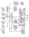
- This ink jet printer comprises: a paper feed motor (which will be also hereinafter referred to as a PF motor) 1 for feeding a paper; a paper feed motor driver 2 for driving the paper feed motor 1; a carriage 3; a carriage motor (which will be also hereinafter referred to as a CR motor) 4; a CR motor driver 5 for driving the carriage motor 4; a DC unit 6; a pump motor 7 for controlling the suction of ink for preventing clogging; a pump motor driver 8 for driving the pump motor 7; a recording head 9, fixed to the carriage 3, for discharging ink to a printing paper 50; a head driver 10 for driving and controlling the recording head 9; a linear type encoder 11 fixed to the carriage 3; a code plate 12 which has slits in regular intervals; a rotary type encoder 13 for use in the PF motor 1; a paper detecting sensor 15 for detecting the position of the rear edge of a paper which is being printed; a CPU 16 for controlling the whole printer; a
- each of the paper feed motor 1 and the CR motor 4 comprises a DC motor.
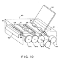
- FIG. 7 The peripheral construction of the carriage 3 of this ink jet printer is shown in FIG. 7.
- the carriage 3 is connected to the carriage motor 4 via the timing belt 31 and the pulley 30 to be driven so as to be guided by a guide member 32 to move in parallel to the platen 25.
- the carriage 3 is provided with the recording head 9 on the surface facing the printing paper.
- the recording head 9 comprises a nozzle row for discharging a black ink and a nozzle row for discharging color inks. Each nozzle is supplied with ink from an ink cartridge 34, and discharges drops of ink to the printing paper to print characters and/or images.
- a capping unit 35 for sealing a nozzle opening of the recording head 9 during non-print
- a pump unit 36 having the pump motor 7 shown in FIG. 6.
- the pump unit 36 When the nozzle opening row of the recording head 9 is clogged with ink, or when the cartridge 34 is exchanged or the like to force the recording head 9 to discharge ink, the pump unit 36 is operated in the sealed state of the recording head 9, to suck ink out of the nozzle opening row by a negative pressure from the pump unit 36. Thus, dust and paper powder adhering to a portion near the nozzle opening row are cleaned. Moreover, bubbles of the recording head 9, together with ink, are discharged to a cap 37.
- This encoder 11 comprises a light emitting diode 11a, a collimator lens 11b, and a detection processing part 11c.
- the detection processing part 11c has a plurality of (four) photodiodes 11d, a signal processing circuit 11e, and two comparators 11f A and 11f B .
- the parallel rays passing through the code plate 12 are incident on each of the photodiodes 11d via a fixed slit (not shown), and converted into electric signals.
- the electric signals outputted from the four photodiodes 11d are processed by the signal processing circuit 11e.
- the signals outputted from the signal processing circuit 11e are compared by the comparators 11f A and 11f B , and the compared results are outputted as pulses.
- the pulses ENC-A and ENC-B outputted from the comparators 11f A and 11f B are outputs of the encoder 11.
- the phase of the pulse ENC-A is different from the phase of the pulse ENC-B by 90 degrees.
- the encoder 4 is designed so that the phase of the pulse ENC-A is advanced from the pulse ENC-B by 90 degrees as shown in FIG. 9(a) when the CR motor 4 is normally rotating, i.e., when the carriage 3 is moving a main scanning direction, and the phase of the pulse ENC-A lags behind the pulse ENC-B by 90 degrees as shown in FIG. 9(b) when the CR motor 4 is reversely rotating.
- the paper 10 inserted into a paper feeding port 61 of a printer 60 is fed into the printer 60 by means of a paper feeding roller 64 which is driven by a paper feeding motor 63.
- the front edge of the paper 50, which has been fed into the printer 60 is detected by, e.g., an optical paper detecting sensor 15.
- the paper 50, the front edge of which has been detected by the paper detecting sensor 15, is fed by means of a paper feed roller 65 and a driven roller 66 which are driven by the PF motor 1.
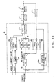
- the DC unit 6 comprises a position calculating part 6a, a subtracter 6b, a target speed calculating part 6c, a speed calculating part 6d, a subtracter 6e, a proportional element 6f, an integrating element 6g, a differentiating element 6h, an adder 6i, a D/A converter 6j, a timer 6k, and an acceleration control part 6m.
- the position calculating part 6a is designed to detect the leading and trailing edges of each of the output pulses ENC-A and ENC-B of the encoder 11 to count the number of the detected edges, and to calculate the position of the carriage 3 on the basis of the counted value. In this counting, when the CR motor 4 is normally rotating, if one edge is detected, "+1" is added, and when the CR motor 4 is reversely rotating, if one edge is detected, "-1" is added.
- Each of the periods of the pulses ENC-A and ENC-B is equal to the distance between adjacent slits of the code plate 12, and the phase of the pulse ENC-A is different from the phase of the pulse ENC-B by 90 degrees.
- the counted value "1" in the above described counting corresponds to 1/4 of the distance between adjacent slits of the code plate 12.
- the subtracter 6b is designed to calculate a position deviation of the actual position of the carriage 3, which is obtained by the position calculating part 6a, from a target position which is fed from the CPU 16.
- the target speed calculating part 6c is designed to calculate a target speed of the carriage 3 on the basis of the position deviation which is the output of the subtracter 6b. This operation is carried out by multiplying the position deviation by a gain K p .
- This gain K p is determined in accordance with the position deviation. Furthermore, the value of the gain K p may be stored in a table (not shown).
- the subtracter 6e is designed to calculate a speed deviation of the actual speed of the carriage 3, which is calculated by the speed calculating part 6d, from a target speed.
- the proportional element 6f is designed to multiply the speed deviation by a constant Gp to output the multiplied result.
- the integrating element 6g is designed to integrate a value which is obtained by multiplying the speed deviation by a constant Gi.
- the differentiating element 6h is designed to multiply a difference between the current speed deviation and the last speed variation by a constant Gd to output the multiplied result. Furthermore, the operations in the proportional element 6f, integrating element 6g and differentiating element 6h are carried out every one period of the output pulse ENC-A of the encoder 11, i.e., in synchronism with the leading edge of the output pulse ENC-A.
- the outputs of the proportional element 6f, integrating element 6g and differentiating element 6h are added by the adder 6i. Then, the added result, i.e., the driving current of the CR motor 4, is fed to the D/A converter 6j to be converted into an analog current. On the basis of the analog current, the CR motor 4 is driven by the driver 5.
- timer 6k and the acceleration control part 6m are used for controlling acceleration
- PID control using the proportional element 6f, integrating element 6g and differentiating element 6h is used for controlling the constant speed and deceleration during acceleration.
- the timer 6k is designed to generate a timer interruption signal every a predetermined time on the basis of a clock signal which is fed from the CPU 16.
- the acceleration control part 6m is designed to integrate a predetermined current value (e.g., 20 mA) into a target current value every time it receives the timer interruption signal, and to feed the integrated result, i.e., the target current value of the DC motor 4 during acceleration, to the D/A converter 6j. Similar to the PID control, the target current value is converted into an analog current by the D/A converter 6j. On the basis of this analog current, the CR motor 4 is driven by the driver.
- a predetermined current value e.g. 20 mA
- the driver 5 has, e.g., four transistors. By turning each of the transistors ON and OFF on the basis of the output of the D/A converter 6j, the driver 5 can be selectively in (a) an operation mode in which the CR motor 4 is normally or reversely rotated, (b) a regenerative brake operation mode (a short brake operation mode, i.e., a mode in which the stopping of the CR motor is maintained), or (c) a mode in which the CR motor is intended to be stopped.
- a regenerative brake operation mode a short brake operation mode, i.e., a mode in which the stopping of the CR motor is maintained
- a mode in which the CR motor is intended to be stopped.
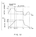
- a start-up initial current value I o is fed from the acceleration control part 6m to the D/A converter 6j. Furthermore, this start-up initial current value I o , together with the start-up command signal, is fed from the CPU 16 to the acceleration control part 6m. Then, this current value I o is converted into an analog current by the D/A converter 6j to be fed to the driver 5, and the CR motor is started up by the driver 5 (see FIG. 12(a), 12(b)).
- the timer 6k After the start-up command signal is received, the timer 6k generates a timer interruption signal every a predetermined time. Every time the acceleration control part 6m receives the timer interruption signal, the acceleration control part 6m integrates a predetermined current value (e.g., 20 mA) into the start-up initial current value I o , to feed the integrated current value to the D/A converter 6j. Then, the integrated current value is converted into an analog current by the D/A converter 6j to be fed to the driver 5. Then, the CR motor is driven by the driver 5 so that the value of the current supplied to the CR motor 4 is the integrated current value, so that the speed of the CR motor 4 increases (see FIG. 12(b)). Therefore, the current value supplied to the CR motor is step-wise as shown in FIG. 12(a).
- a predetermined current value e.g. 20 mA
- the D/A converter 6j selects and incorporates the output of the acceleration control part 6m.
- the integration of the current value in the acceleration control part 6m is carried out until the integrated current value becomes a constant current value I s .
- the acceleration control part 6m stops the integration, and supplies the constant current value I s to the D/A converter 6j.
- the CR motor 4 is driven by the driver 5 so that the value of the current supplied to the CR motor 4 becomes the current value I s (see FIG. 12(a)).
- the acceleration control part 6m controls the CR motor 4 so as to reduce the current, which is supplied to the CR motor 4, when the speed of the CR motor 4 becomes a predetermined speed V 1 (see time t 2 ). At this time, the speed of the CR motor 4 further increases. However, when the speed of the CR motor 4 reaches a predetermined speed V c (see time t 3 in FIG. 12(b)), the D/A converter 6j selects the output of the PID control system, i.e., the output of the adder 6i, to carry out the PID control.
- the target speed is calculated on the basis of the position deviation of the actual position, which is obtained from the output of the encoder 11, from the target position.
- the proportional element 6f, integrating element 6g and differentiating element 6h are operated on the basis of the speed deviation of the actual speed, which is obtained from the output of the encoder 11, from the target speed to carry out the proportional, integrating and differentiating operations.
- the CR motor 4 is controlled on the basis of the sum of these calculated results.
- the above described proportional, integrating and differentiating operations are carried out in synchronism with, e.g., the leading edge of the output pulse ENC-A of the encoder 11..
- the speed of the DC motor 4 is controlled so as to be a desired speed V e .
- the predetermined speed V c is preferably a value of 70 % to 80 % of the desired speed V e .
- the construction of the first preferred embodiment of a control unit for controlling a motor for use in a printer according to the present invention is shown in FIG. 1.
- the control unit in this preferred embodiment is used for controlling a carriage motor 4 comprising a DC motor for use in an ink jet printer, and comprises a DC unit 80.
- the DC unit 80 includes an average speed measuring part 90, which is substituted for the speed calculating part 6d of the DC unit 6 shown in FIG. 11, and a subtracter 96 which is newly provided.
- the average speed measuring part 90 comprises a speed calculating part 91, a memory 92, and an average speed calculating part 93.
- the speed calculating part 91 has the same construction as that of the speed calculating part 6d shown in FIG. 11.
- the speed calculating part 91 is designed to calculate a speed of the CR motor 4, i.e., a speed of the carriage 3, on the basis of the output of the encoder 11.
- This operation is carried out in synchronism with the leading edge of the output pulse ENC-A of the encoder 11.
- the memory 92 is designed to store therein n speed data from the last calculated result to a calculated result of n (n ⁇ 1) before, which have been calculated by the speed calculating part 91. After the average speed calculating part 93 reads n speed data, the memory 92 is designed to store therein the current speed which is calculated by the speed calculating part 91 in place of the calculated speed of n before.
- the average speed calculating part 93 is designed to calculate an average of two speed data of the current speed data, which are calculated by the speed calculating part 91, and speed data of n before, which have been stored in the memory 92.
- the subtracter 6e is designed to calculate a speed deviation of the current speed, which is calculated by the speed calculating part 91, from a target speed, which is the output of the target speed calculating part 6c, to transmit the calculated speed deviation to the integrating element 6g.
- the subtracter 96 is designed to calculate a speed deviation of the average speed, which is the output of the average speed calculating part 93, from the target speed, which is the output of the target speed calculating part 6c, to transmit the calculated speed deviation to the proportional element 6f and the differentiating element 6h.
- the proportional element 6f is designed to multiply the output of the subtracter 96 by a constant Gp to transmit the multiplied result to the adder 6i.
- the integrating element 6g is designed to integrate a value, which has been obtained by multiplying the output of the subtracter 6e by a constant Gi, to transmit the integrated result to the adder 6i.
- the differentiating element 6h is designed to multiply a difference between the current speed deviation and the last speed deviation by a constant Gd to transmit the multiplied result to the adder 6i. Furthermore, the operations in the proportional element 6f, integrating element 6g and differentiating element 6h are carried out in synchronism with the leading edge of the output pulse ENC-A of the encoder 11.
- the outputs of the proportional element 6f, integrating element 6g and differentiating element 6h are added up by the adder 6i. Then, the added result, i.e., the current for driving the CR motor 4 which causes the above described speed deviation to be zero, is fed to the D/A converter 6j to be converted an analog current. On the basis of this analog current, the CR motor 4 is driven by the driver 5.
- the number n used for calculating the average speed approximates to T v / (2t v ) assuming that the period of the fluctuation in speed of the CR motor 4 is T v and that the period of the operation of the speed in the speed calculating part 91 is t v .
- the number n used for calculating the average speed preferably meets the following expression.
- the same effects can be obtained if the speed deviation is inputted to only the differentiating element 6h and if the speed deviation of the output of the speed calculating part 91 from the target speed is inputted to the proportional element 6f and the integrating element 6f.
- the same effects can be obtained if the speed deviation of the average speed from the target speed is inputted to all of the proportional element 6f, the integrating element 6g and the differentiating element 6h.
- the position calculating part 6a has counted the leading and trailing edges of the output pulses ENC-A and ENC-B of the encoder 11 to multiply the counted value by the distance between adjacent slits of the code plate 12 of the encoder 11, the leading and trailing edges of the output pulses ENC-A and ENC-B may be counted without the multiplication by the distance between adjacent slits, to be outputted.
- the target position is also expressed by the number of pulses, and the output of the speed calculating part 91 is the inverse number of the period of the output pulse ENC-A of the encoder 11.
- the average speed calculating part 93 calculates an average value of the inverse number of the period of the output pulse ENC-A to output the calculated average value.
- the average speed calculating part 93 has calculated the average speed of the current calculated speed and the calculated speed of n before in the above described first preferred embodiment
- the average value (the average speed) of k+1 calculated speed data from the current calculated speed to a calculated speed of k (n > k ⁇ 1) before and k+1 calculated speed data from a calculated speed of n before and a calculated speed of n+k before may be obtained.
- n+k calculated speed data from the last calculated speed to the calculated speed of n+k before are stored in the memory 92.
- the average speed calculating part 93 may be designed to obtain an average value of m (n-1 ⁇ m ⁇ 2) calculated speed data, which are selected from n calculated speed data from the current calculated speed to a calculated speed of n-1 before and which include the current calculated speed, and m calculated speed data which are selected from n calculated speed data from a calculated speed of n before to a calculated speed of 2n-1 and which correspond to the m calculated speed data.
- the calculated speed data corresponding to the current calculated speed data are the calculated speed data of n before
- the calculated speed data corresponding to the calculated speed data of k (n-1 ⁇ k ⁇ 1) before are the calculated speed data of n+k before.
- the speed of the carriage 3 fluctuates under the influence of (a) the fluctuation in speed of the CR motor 4, (b) the fluctuation in speed of the timing belt 31, and (c) the fluctuation in speed of the pulley. Therefore, it is not only required to suppress the fluctuation in speed of the CR motor 4, but it is also required to suppress the fluctuation in speed due to other factors. In the following second preferred embodiment, the fact that the fluctuation in speed due to other factors can be suppressed will be described below.
- FIG. 5 The construction of the second preferred embodiment of a control unit for controlling a motor for use in a printer according to the present invention is shown in FIG. 5.
- the control unit in this second preferred embodiment is used for controlling the speed of a CR motor of an ink jet printer.
- a DC unit 80A is substituted for the DC unit 80 of the control unit in the first preferred embodiment shown in FIG. 1.
- the DC unit 80A has an average speed measuring part 90A, a subtracter 97 and a differentiating element 98 which are newly added to the DC unit 80 shown in FIG. 1.
- the average speed measuring part 90A has substantially the same construction as that of the average speed measuring part 90, and comprises a speed calculating part 91A, a memory 92A and an average speed calculating part 93A.
- the speed calculating part 91A has the same construction as that of the speed calculating part 91, and is designed to calculate the speed of the CR motor 4, i.e., the speed of the carriage 3, on the basis of the output pulse ENC-A of the encoder 11. This operation is carried out in synchronism with the leading edge of the output pulse ENC-A of the encoder 11.
- the memory 92A is designed to store therein m speed data from the last calculated result to the calculated result of m (m ⁇ 2) before, which are calculated by the speed calculating part 91A. After the average speed calculating part 93A reads data of m before, the memory 92A is designed to store therein the current calculated speed, which is calculated by the speed calculating part 91A, in place of the calculated speed of m before.
- the average speed calculating part 93A is designed to calculate an average value (an average speed) of the current speed data, which are calculated by the speed calculating part 91A, and the calculated speed of m before, to transmit the calculated result to the subtracter 97.
- the subtracter 97 is designed to calculate a speed deviation of the average speed, which is the output of the average speed calculating part 93A, from the target speed which is the output of the target speed calculating means 6c.
- the differentiating element 98 is designed to multiply the difference between the current speed deviation and the last speed deviation by a constant Gd A , to transmit the multiplied result to the adder 6i.
- the sum of the outputs of the proportional element 6f, integrating element 6g, differentiating element 6h and differentiating element 98 is calculated by the adder 6i.
- the output of the adder 6i i.e., the driving current for the CR motor 4 which causes the speed deviation to be zero, is fed to the D/A converter 6j to be converted an analog current. On the basis of this analog current, the CR motor 4 is driven by the driver 5.
- the number m used for calculating the average speed approximates to T vA /(2t vA ) assuming that the period of the fluctuation in speed to be suppressed other than the fluctuation in speed of the CR motor 4 is T vA and that the operation period in the speed calculating part 91A is t vA .
- control unit in this second preferred embodiment can suppress the fluctuation in speed of the CR motor 4, and can also suppress the fluctuation in speed due to other factors.
- the operation period of the speed calculating part 91A has been equal to the period of the output pulse ENC-A of the encoder 11.
- the operation of the speed calculating part 91A is preferably carried out in synchronism with the leading and trailing edges of each of the output pulses ENC-A and ENC-B of the encoder, or on the basis of the output pulse of a higher definition encoder.
- the average speed calculating part 93A has calculated the average speed of the current calculated speed and the calculated speed of m before.
- the average value (the average speed) of k+1 calculated speed data from the current calculated speed to the calculated speed of k (m > k ⁇ 1) before and k+1 calculated speed data from the calculated speed of m before to the calculated speed of m+k before may be obtained.
- the memory 92 stores therein m+k calculated speed data from the last calculated speed to the calculated speed of m+k before.
- the DC motor has been described in the above described first and second preferred embodiments, the present invention can also be applied to an AC motor.
- This third preferred embodiment relates to a method for controlling a motor for use in a printer, and the control procedure thereof is shown in FIG. 14.
- the speed of a motor for use in a printer is detected in a predetermined period t v to be stored (see step F1 in FIG. 14) .
- an average speed is calculated using at least the current detected speed and a detected speed which has been detected n (n ⁇ 2), which corresponds to substantially half period in the fluctuation in speed of the motor, before the timing in detecting the current detected speed (see step F2 in FIG. 14).
- the speed of the motor is controlled on the basis of the speed deviation of the average speed from the target speed (see step F3 in FIG. 14).
- the influence of the fluctuation in speed is removed from the calculated average speed, so that the fluctuation in speed can be suppressed by controlling the speed of the motor on the basis of the speed deviation of the average speed from the target speed.
- the average speed of k+1 detected speeds from the current detected speed to the detected speed of k (n > k ⁇ 0) before and k+1 detected speeds from the detected speed of n before to the detected speed of n+k before may be obtained.
- the motor may be controlled on the basis of the sum of the speed deviation and the output of the differentiating element which is operated on the basis of the speed deviation.
- FIGS. 15 and 16 are a perspective view and block diagram showing an example of a computer system 130 which uses a storage medium, in which a print control program in this preferred embodiment has been recorded.
- the computer system 130 comprises a computer body 130 including a CPU, a display unit 132, such as a CRT, an input unit 133, such as a keyboard or mouse, and a printer 134 for carrying out a print.
- a computer body 130 including a CPU, a display unit 132, such as a CRT, an input unit 133, such as a keyboard or mouse, and a printer 134 for carrying out a print.
- the computer body 131 comprises an internal memory 135 of a RAM, and a built-in or exterior memory unit 136.
- a flexible or floppy disk (FD) drive 137, a CD-ROM drive 138 and a hard disk drive (HD) unit 139 are mounted as the memory unit 136.
- a flexible disk or floppy disk (FD) 141 which is inserted into a slot of the FD drive 137 to be used, a CD-ROM 142 which is used for the CD-ROM drive 138, or the like is used as a storage medium 140 for use in the memory unit 136.
- the FD 141 or the CD-ROM 142 is used as the storage medium for use in a typical computer system.
- the control program of the present invention may be recorded in, e.g., a ROM chip 143 serving as a nonvolatile memory which is built in the printer 134.
- the storage medium may be any one of FDs, CD-ROMs, MOs (Magneto-Optical) disks, DVDs (Digital Versatile Disks), other optical recording disks, card memories, and magnetic tapes.
- the storage medium 140 in this preferred embodiment is designed to carry out a control procedure including steps. F1 through F3 shown in FIG. 14. That is, the storage medium 140 in this preferred embodiment may carry out the steps of detecting the speed of a motor in a predetermined period t v , calculating an average speed using at least the current detected speed and a detected speed which has been detected n (n ⁇ 2), which corresponds to substantially half period in the fluctuation in speed of the motor, before the timing in detecting the current detected speed, and controlling the speed of the motor on the basis of a speed deviation of the average speed from the target speed.
Landscapes
- Character Spaces And Line Spaces In Printers (AREA)
- Control Of Electric Motors In General (AREA)
- Control Of Direct Current Motors (AREA)
- Ink Jet (AREA)
- Accessory Devices And Overall Control Thereof (AREA)
Claims (18)
- Steuereinheit zum Steuern eines Motors in einem Drucker, wobei die Steuereinheit umfasst:einen Geschwindigkeits-Erfassungsteil (11, 91), der eine Geschwindigkeit des Motors in einer vorgegebenen Periode tv erfasst;einen Durchschnittsgeschwindigkeits-Berechnungsteil (93), der eine Durchschnittsgeschwindigkeit auf Basis einer von dem Geschwindigkeits-Erfassungsteil aktuellen erfassten Geschwindigkeit und einer zuvor erfassten Geschwindigkeit berechnet, die n (≧ 2) Perioden tv vor einem. Erfassen der aktuellen Geschwindigkeit erfasst worden ist, was im Wesentlichen einer halben Periode einer Schwankung der Geschwindigkeit des Motors Tv entspricht; undeinen Geschwindigkeits-Steuerteil (6f, 6h), der die Geschwindigkeit des Motors auf Basis einer Geschwindigkeitsabweichung der Durchschnittsgeschwindigkeit von einer Sollgeschwindigkeit des Motors steuert.
- Steuereinheit zum Steuern eines Motors in einem Drucker nach Anspruch 1, wobei, wenn davon ausgegangen ist, dass die Periode der Schwankung der Geschwindigkeit des Motors Tv ist, die Anzahl n, die zum Berechnen der Durchschnittsgeschwindigkeit verwendet wird, den folgenden Ausdruck erfüllt:

- Steuereinheit zum Steuern eines Motors in einem Drucker nach Anspruch 2, wobei der Durchschnittsgeschwindigkeits-Berechnungsteil eine Durchschnittsgeschwindigkeit von k + 1 erfassten Geschwindigkeiten von der aktuellen erfassten Geschwindigkeit bis zu einer erfassten Geschwindigkeit k (n > k ≧ 0) davor, und k + 1 erfassten Geschwindigkeiten von einer erfassten Geschwindigkeit n davor bis zu einer erfassten Geschwindigkeit k + 1 davor berechnet.
- Steuereinheit zum Steuern eines Motors in einem Drucker nach Anspruch 3, wobei der Geschwindigkeits-Steuerteil ein Differenzierungselement (6d) aufweist, das auf Basis der Geschwindigkeitsabweichung der Durchschnittsgeschwindigkeit von der Sollgeschwindigkeit arbeitet.
- Steuereinheit zum Steuern eines Motors in einem Drucker nach Anspruch 4, wobei der Geschwindigkeits-Steuerteil ein Proportionalelement (6f) aufweist, das auf Basis der Geschwindigkeitsabweichung der Durchschnittsgeschwindigkeit von der Sollgeschwindigkeit arbeitet.
- Steuereinheit zum Steuern eines Motors in einem Drucker nach Anspruch 5, wobei der Geschwindigkeits-Erfassungsteil einen Codierer (11), der einen Ausgangsimpuls entsprechend der Drehung des Motors erzeugt, und einen Geschwindigkeits-Berechnungsteil (91) umfasst, der die Geschwindigkeit des Motors in einer Periode des Ausgangsimpulses auf Basis des Ausgangsimpulses des Codierers berechnet.
- Steuereinheit zum Steuern eines Motors in einem Drucker nach Anspruch 6, wobei der Motor ein Schlittenmotor zum Einsatz in einem Tintenstrahldrucker ist und der Codierer den Ausgangsimpuls entsprechend der Bewegung eines Schlittens erzeugt, der von dem Schlittenmotor über eine Riemenscheibe, die an der Drehwelle des Schlittenmotors angebracht ist, und über einen Steuerriemen angetrieben wird, der von der Riemenscheibe angetrieben wird.
- Steuereinheit zum Steuern eines Motors in einem Drucker nach Anspruch 7, wobei, wenn davon ausgegangen wird, dass der Abstand zwischen benachbarten Schlitzen einer Codeplatte des Codierers A ist, dass eine Teilkreislänge der Riemenscheibe L ist und dass die Anzahl von Phasen des Motors p ist, n den folgenden Ausdruck erfüllt:

- Steuereinheit zum Steuern eines Motors in einem Drucker nach Anspruch 7 oder 8, wobei der Geschwindigkeits-Steuerteil des Weiteren umfasst:einen zweiten Geschwindigkeits-Berechnungsteil (91A), der die Geschwindigkeit des Motors in einer zweiten vorgegebenen Periode auf Basis des Ausgangsimpulses des Codierers berechnet;einen zweiten Durchschnittsgeschwindigkeits-Berechnungsteil (93A), der die Durchschnittsgeschwindigkeit unter Verwendung wenigstens der aktuellen berechneten Geschwindigkeit, die durch den zweiten Geschwindigkeits-Berechnungsteil berechnet wird, und einer m (m ≧ 2) davor gewesenen berechneten Geschwindigkeit berechnet; undein zweites Differenzierungselement (98), das auf der Basis einer Geschwindigkeitsabweichung des Ausgangs des zweiten Durchschnittsgeschwindigkeits-Berechnungsteils von der Sollgeschwindigkeit arbeitet.
- Steuereinheit zum Steuern eines Motors in einem Drucker nach einem der Ansprüche 1 bis 9, wobei der Motor ein Gleichstrommotor ist.
- Verfahren zum Steuern eines Motors in einem Drucker, wobei das Verfahren die folgenden Schritte umfasst:Erfassen einer Geschwindigkeit des Motors in einer vorgegebenen Periode tv;Berechnen einer Durchschnittsgeschwindigkeit auf Basis einer aktuellen erfassten Geschwindigkeit und einer zuvor erfassten Geschwindigkeit von dem Erfassen, die n (≧ 2) Perioden tv vor dem Erfassen der aktuellen Geschwindigkeit erfasst worden ist, was im Wesentlichen einer halben Periode einer Schwankung der Geschwindigkeit des Motors Tv entspricht; undSteuern der Geschwindigkeit des Motors auf Basis einer Geschwindigkeitsabweichung der Durchschnittsgeschwindigkeit von einer Sollgeschwindigkeit des Motors.
- Verfahren zum Steuern eines Motors in einem Drucker nach Anspruch 11, wobei, wenn davon ausgegangen wird, dass die Periode der Schwankung der Geschwindigkeit des Motors Tv ist, die Anzahl n, die zum Berechnen der Durchschnittsgeschwindigkeit verwendet wird, den folgenden Ausdruck erfüllt:

- Verfahren zum Steuern eines Motors in einem Drucker nach Anspruch 12, wobei mit dem Schritt des Berechnens der Durchschnittsgeschwindigkeit eine Durchschnittsgeschwindigkeit von k + 1 erfassten Geschwindigkeiten von der aktuellen erfassten Geschwindigkeit zu einer erfassten Geschwindigkeit k (n > k ≧ 0) davor und k + 1 erfassten Geschwindigkeiten von einer erfassten Geschwindigkeit n davor bis zu einer erfassten Geschwindigkeit k + 1 davor berechnet wird.
- Verfahren zum Steuern eines Motors in einem Drucker nach Anspruch 13, wobei mit dem Schritt des Steuerns der Geschwindigkeit des Motors die Geschwindigkeit des Motors auf Basis der Summe der Geschwindigkeitsabweichung und des Ausgangs des Differenzierungselementes gesteuert wird, das auf der Basis der Geschwindigkeitsabweichung arbeitet.
- Verfahren zum Steuern eines Motors in einem Drucker nach Anspruch 14, wobei der Schritt des Erfassens der Geschwindigkeit des Motors einen Schritt des Berechnens der Geschwindigkeit des Motors in einer Periode eines Ausgangsimpulses eines Codierers, der den Ausgangsimpuls entsprechend der Drehung des Motors erzeugt, auf Basis des Ausgangsimpulses des Codierers einschließt.
- Verfahren zum Steuern eines Motors in einem Drucker nach Anspruch 15, wobei der Motor ein Schlittenmotor zum Einsatz in einem Tintenstrahldrucker ist.
- Verfahren zum Steuern eines Motors in einem Drucker nach einem der Ansprüche 11 bis 16, wobei der Motor ein Gleichstrommotor ist.
- Computerlesbares Speichermedium, das Steuerprogrammcode zum Steuern eines Motors in einem Drucker speichert, wobei es umfasst:erste Programmcodemittel zum Erfassen der Geschwindigkeit des Motors in einer vorgegebenen Periode tv;zweite Programmcodemittel zum Berechnen einer Durchschnittsgeschwindigkeit unter Verwendung wenigstens einer aktuellen erfassten Geschwindigkeit und einer erfassten Geschwindigkeit die n (≧ 2) Perioden tv vor einem Zeitpunkt erfasst worden ist, zu dem die aktuelle Geschwindigkeit erfasst wird, was im Wesentlichen einer halben Periode einer Schwankung der Geschwindigkeit des Motors Tv entspricht; unddritte Programmcodemittel zum Steuern der Geschwindigkeit des Motors auf Basis einer Geschwindigkeitsabweichung der Durchschnittsgeschwindigkeit von einer Sollgeschwindigkeit des Motors.
Applications Claiming Priority (4)
| Application Number | Priority Date | Filing Date | Title |
|---|---|---|---|
| JP21107699 | 1999-07-26 | ||
| JP21107699 | 1999-07-26 | ||
| JP2000141661A JP3859115B2 (ja) | 1999-07-26 | 2000-05-15 | プリンタ用モータの制御装置および制御方法ならびに制御プログラムを記録した記録媒体 |
| JP2000141661 | 2000-05-15 |
Publications (3)
| Publication Number | Publication Date |
|---|---|
| EP1072425A2 EP1072425A2 (de) | 2001-01-31 |
| EP1072425A3 EP1072425A3 (de) | 2001-02-07 |
| EP1072425B1 true EP1072425B1 (de) | 2006-03-29 |
Family
ID=26518419
Family Applications (1)
| Application Number | Title | Priority Date | Filing Date |
|---|---|---|---|
| EP00306297A Expired - Lifetime EP1072425B1 (de) | 1999-07-26 | 2000-07-24 | Steuereinheit und Verfahren zum Steuern eines Motors zur Vewendung in einem Drucker und Steuerungsprogramm speicherndes Speichermedium |
Country Status (6)
| Country | Link |
|---|---|
| US (3) | US6528962B1 (de) |
| EP (1) | EP1072425B1 (de) |
| JP (1) | JP3859115B2 (de) |
| CN (1) | CN1120093C (de) |
| AT (1) | ATE321669T1 (de) |
| DE (1) | DE60026942T2 (de) |
Families Citing this family (17)
| Publication number | Priority date | Publication date | Assignee | Title |
|---|---|---|---|---|
| JP3832712B2 (ja) * | 2000-09-21 | 2006-10-11 | セイコーエプソン株式会社 | 印刷制御装置および制御方法ならびに印刷制御プログラムを記録した記録媒体 |
| JP3687606B2 (ja) | 2001-12-20 | 2005-08-24 | ブラザー工業株式会社 | モータ制御方法及び装置 |
| US7026775B2 (en) * | 2001-12-20 | 2006-04-11 | Brother Kogyo Kabushiki Kaisha | Method and apparatus for controlling speed of moving body |
| JP2004172854A (ja) | 2002-11-19 | 2004-06-17 | Seiko Epson Corp | イメージセンサコントローラ、電子機器、及びイメージセンサの制御方法 |
| JP2004170614A (ja) | 2002-11-19 | 2004-06-17 | Seiko Epson Corp | 電子機器 |
| JP2004172861A (ja) | 2002-11-19 | 2004-06-17 | Seiko Epson Corp | 電子機器コントローラ及び電子機器の制御方法 |
| KR100777450B1 (ko) | 2005-05-28 | 2007-11-21 | 삼성전자주식회사 | 엔코더 속도 보정 방법 및 장치 |
| US8021469B2 (en) | 2005-07-14 | 2011-09-20 | Access Business Group International Llc | Control methods for an air treatment system |
| JP4994768B2 (ja) * | 2005-12-09 | 2012-08-08 | キヤノン株式会社 | 画像形成装置 |
| JP2007182265A (ja) * | 2005-12-29 | 2007-07-19 | Brother Ind Ltd | シート搬送装置 |
| JP4781127B2 (ja) * | 2006-02-24 | 2011-09-28 | オムロンオートモーティブエレクトロニクス株式会社 | 電動機制御装置 |
| JP4483812B2 (ja) | 2006-03-24 | 2010-06-16 | セイコーエプソン株式会社 | 印刷装置、スティックスリップ対応方法、プログラム、及び印刷システム |
| US7898207B2 (en) * | 2007-12-04 | 2011-03-01 | Pitney Bowes Inc. | Method for controlling a DC motor |
| JP5371419B2 (ja) * | 2008-12-26 | 2013-12-18 | キヤノン株式会社 | 機器におけるモータの制御方法 |
| JP5610838B2 (ja) * | 2010-05-11 | 2014-10-22 | キヤノン株式会社 | モータを備えた機器 |
| CN107718912A (zh) * | 2017-11-21 | 2018-02-23 | 珠海冰河电子技术有限公司 | 一种打印机速度控制方法及装置 |
| CN114337404B (zh) * | 2021-12-30 | 2024-06-18 | 海信(广东)空调有限公司 | 直流电机控制方法、空调器和计算机可读存储介质 |
Family Cites Families (12)
| Publication number | Priority date | Publication date | Assignee | Title |
|---|---|---|---|---|
| US3863118A (en) * | 1973-01-26 | 1975-01-28 | Warner Electric Brake & Clutch | Closed-loop speed control for step motors |
| US4103216A (en) * | 1976-05-28 | 1978-07-25 | Tally Corporation | Stepping motor closed loop constant velocity control system |
| US4490796A (en) * | 1981-10-16 | 1984-12-25 | International Business Machines Corporation | Print head motor control system using analog and digital feedback |
| JPS60118077A (ja) * | 1983-11-29 | 1985-06-25 | Oki Electric Ind Co Ltd | プリンタのスペ−シング速度制御方法 |
| US4775945A (en) * | 1985-12-11 | 1988-10-04 | International Business Machines Corporation | Print head motor control system with automatic drive parameter calculations |
| JPH07115521B2 (ja) * | 1988-11-30 | 1995-12-13 | 沖電気工業株式会社 | 直流モータの速度制御装置 |
| JP3230364B2 (ja) * | 1994-03-03 | 2001-11-19 | 株式会社明電舎 | 速度制御系における速度推定演算処理方法 |
| JP3296527B2 (ja) * | 1994-08-05 | 2002-07-02 | 株式会社安川電機 | モータ速度制御装置 |
| JPH09202014A (ja) * | 1996-01-24 | 1997-08-05 | Brother Ind Ltd | プリンタ |
| EP0807528B1 (de) * | 1996-05-15 | 2001-12-12 | Océ-Technologies B.V. | Verfahren und System zur Detektierung einer Wagenlage |
| JP3281561B2 (ja) * | 1996-12-25 | 2002-05-13 | シャープ株式会社 | モータ速度制御装置 |
| US6111384A (en) * | 1998-05-26 | 2000-08-29 | Eastman Kodak Company | Method for controlling motor speed |
-
2000
- 2000-05-15 JP JP2000141661A patent/JP3859115B2/ja not_active Expired - Fee Related
- 2000-07-24 EP EP00306297A patent/EP1072425B1/de not_active Expired - Lifetime
- 2000-07-24 AT AT00306297T patent/ATE321669T1/de not_active IP Right Cessation
- 2000-07-24 DE DE60026942T patent/DE60026942T2/de not_active Expired - Lifetime
- 2000-07-26 CN CN00121956A patent/CN1120093C/zh not_active Expired - Fee Related
- 2000-07-26 US US09/625,994 patent/US6528962B1/en not_active Expired - Lifetime
-
2002
- 2002-09-25 US US10/253,498 patent/US20030025471A1/en not_active Abandoned
-
2005
- 2005-03-09 US US11/074,761 patent/US20050146300A1/en not_active Abandoned
Also Published As
| Publication number | Publication date |
|---|---|
| US6528962B1 (en) | 2003-03-04 |
| EP1072425A2 (de) | 2001-01-31 |
| ATE321669T1 (de) | 2006-04-15 |
| JP2001103778A (ja) | 2001-04-13 |
| CN1120093C (zh) | 2003-09-03 |
| CN1282015A (zh) | 2001-01-31 |
| DE60026942T2 (de) | 2006-08-24 |
| DE60026942D1 (de) | 2006-05-18 |
| US20030025471A1 (en) | 2003-02-06 |
| US20050146300A1 (en) | 2005-07-07 |
| EP1072425A3 (de) | 2001-02-07 |
| JP3859115B2 (ja) | 2006-12-20 |
Similar Documents
| Publication | Publication Date | Title |
|---|---|---|
| US6747429B2 (en) | Print control system, print control method, and recording medium having recorded print control program | |
| EP1072425B1 (de) | Steuereinheit und Verfahren zum Steuern eines Motors zur Vewendung in einem Drucker und Steuerungsprogramm speicherndes Speichermedium | |
| US7712857B2 (en) | Printing apparatus, printing method, program, storage medium, and computer system | |
| EP1602504B1 (de) | Motorsteuerungsvorrichtung und -verfahren | |
| EP1088674B1 (de) | Einheit und Verfahren zum Steuern eines in einem Drucker zu verwendenden Motors und Speichermedien zum Speichern des Steuerprogrammes | |
| EP1124320B1 (de) | Verfahren und Vorrichtung zur Motorsteuerung | |
| US6390698B1 (en) | Apparatus and method of detecting home position of carriage and storage medium storing home position detection program | |
| JP3832174B2 (ja) | モータ制御装置及び制御方法 | |
| US6967729B1 (en) | Control unit and method for controlling motor for use in printer, and storage medium storing control program | |
| JP3570617B2 (ja) | Dcモータ制御装置及び制御方法 | |
| JP2001251878A (ja) | モータ制御装置及び制御方法 | |
| JP3705061B2 (ja) | モータの制御装置およびその制御方法ならびにモータの制御プログラムを記録した記録媒体 | |
| JP3893853B2 (ja) | プリンタ用モータの制御装置および制御方法 | |
| JP3871181B2 (ja) | 印刷制御装置および制御方法ならびに印刷制御プログラムを記録した記録媒体 | |
| JP2001224189A (ja) | モータ制御方法及び制御装置 | |
| JP3849908B2 (ja) | 印刷制御装置および印刷制御方法 | |
| JP4432055B2 (ja) | プリンタ用モータの制御装置および制御方法 | |
| JP2005200222A (ja) | 印刷制御装置および制御方法ならびに印刷制御プログラムを記録した記録媒体 | |
| JP2001315395A (ja) | 印刷制御装置および印刷制御方法ならびに印刷制御プログラムを記録した記録媒体 | |
| JP2001078475A (ja) | モータ制御装置及び制御方法 | |
| JP2002283559A (ja) | 印刷制御装置および印刷制御方法ならびに印刷制御プログラムを記録した記録媒体 |
Legal Events
| Date | Code | Title | Description |
|---|---|---|---|
| PUAI | Public reference made under article 153(3) epc to a published international application that has entered the european phase |
Free format text: ORIGINAL CODE: 0009012 |
|
| PUAL | Search report despatched |
Free format text: ORIGINAL CODE: 0009013 |
|
| AK | Designated contracting states |
Kind code of ref document: A2 Designated state(s): AT BE CH CY DE DK ES FI FR GB GR IE IT LI LU MC NL PT SE |
|
| AX | Request for extension of the european patent |
Free format text: AL;LT;LV;MK;RO;SI |
|
| AK | Designated contracting states |
Kind code of ref document: A3 Designated state(s): AT BE CH CY DE DK ES FI FR GB GR IE IT LI LU MC NL PT SE |
|
| AX | Request for extension of the european patent |
Free format text: AL;LT;LV;MK;RO;SI |
|
| 17P | Request for examination filed |
Effective date: 20010614 |
|
| AKX | Designation fees paid |
Free format text: AT BE CH CY DE DK ES FI FR GB GR IE IT LI LU MC NL PT SE |
|
| 17Q | First examination report despatched |
Effective date: 20040907 |
|
| GRAP | Despatch of communication of intention to grant a patent |
Free format text: ORIGINAL CODE: EPIDOSNIGR1 |
|
| GRAS | Grant fee paid |
Free format text: ORIGINAL CODE: EPIDOSNIGR3 |
|
| GRAA | (expected) grant |
Free format text: ORIGINAL CODE: 0009210 |
|
| AK | Designated contracting states |
Kind code of ref document: B1 Designated state(s): AT BE CH CY DE DK ES FI FR GB GR IE IT LI LU MC NL PT SE |
|
| PG25 | Lapsed in a contracting state [announced via postgrant information from national office to epo] |
Ref country code: IT Free format text: LAPSE BECAUSE OF FAILURE TO SUBMIT A TRANSLATION OF THE DESCRIPTION OR TO PAY THE FEE WITHIN THE PRE;WARNING: LAPSES OF ITALIAN PATENTS WITH EFFECTIVE DATE BEFORE 2007 MAY HAVE OCCURRED AT ANY TIME BEFORE 2007. THE CORRECT EFFECTIVE DATE MAY BE DIFFERENT FROM THE ONE RECORDED.SCRIBED TIME-LIMIT Effective date: 20060329 Ref country code: AT Free format text: LAPSE BECAUSE OF FAILURE TO SUBMIT A TRANSLATION OF THE DESCRIPTION OR TO PAY THE FEE WITHIN THE PRESCRIBED TIME-LIMIT Effective date: 20060329 Ref country code: BE Free format text: LAPSE BECAUSE OF FAILURE TO SUBMIT A TRANSLATION OF THE DESCRIPTION OR TO PAY THE FEE WITHIN THE PRESCRIBED TIME-LIMIT Effective date: 20060329 Ref country code: CH Free format text: LAPSE BECAUSE OF FAILURE TO SUBMIT A TRANSLATION OF THE DESCRIPTION OR TO PAY THE FEE WITHIN THE PRESCRIBED TIME-LIMIT Effective date: 20060329 Ref country code: LI Free format text: LAPSE BECAUSE OF FAILURE TO SUBMIT A TRANSLATION OF THE DESCRIPTION OR TO PAY THE FEE WITHIN THE PRESCRIBED TIME-LIMIT Effective date: 20060329 Ref country code: NL Free format text: LAPSE BECAUSE OF FAILURE TO SUBMIT A TRANSLATION OF THE DESCRIPTION OR TO PAY THE FEE WITHIN THE PRESCRIBED TIME-LIMIT Effective date: 20060329 |
|
| REG | Reference to a national code |
Ref country code: GB Ref legal event code: FG4D |
|
| REG | Reference to a national code |
Ref country code: CH Ref legal event code: EP |
|
| REG | Reference to a national code |
Ref country code: IE Ref legal event code: FG4D |
|
| REF | Corresponds to: |
Ref document number: 60026942 Country of ref document: DE Date of ref document: 20060518 Kind code of ref document: P |
|
| PG25 | Lapsed in a contracting state [announced via postgrant information from national office to epo] |
Ref country code: SE Free format text: LAPSE BECAUSE OF FAILURE TO SUBMIT A TRANSLATION OF THE DESCRIPTION OR TO PAY THE FEE WITHIN THE PRESCRIBED TIME-LIMIT Effective date: 20060629 Ref country code: DK Free format text: LAPSE BECAUSE OF FAILURE TO SUBMIT A TRANSLATION OF THE DESCRIPTION OR TO PAY THE FEE WITHIN THE PRESCRIBED TIME-LIMIT Effective date: 20060629 |
|
| PG25 | Lapsed in a contracting state [announced via postgrant information from national office to epo] |
Ref country code: ES Free format text: LAPSE BECAUSE OF FAILURE TO SUBMIT A TRANSLATION OF THE DESCRIPTION OR TO PAY THE FEE WITHIN THE PRESCRIBED TIME-LIMIT Effective date: 20060710 |
|
| PG25 | Lapsed in a contracting state [announced via postgrant information from national office to epo] |
Ref country code: IE Free format text: LAPSE BECAUSE OF NON-PAYMENT OF DUE FEES Effective date: 20060724 |
|
| PG25 | Lapsed in a contracting state [announced via postgrant information from national office to epo] |
Ref country code: MC Free format text: LAPSE BECAUSE OF NON-PAYMENT OF DUE FEES Effective date: 20060731 |
|
| PG25 | Lapsed in a contracting state [announced via postgrant information from national office to epo] |
Ref country code: PT Free format text: LAPSE BECAUSE OF FAILURE TO SUBMIT A TRANSLATION OF THE DESCRIPTION OR TO PAY THE FEE WITHIN THE PRESCRIBED TIME-LIMIT Effective date: 20060829 |
|
| REG | Reference to a national code |
Ref country code: CH Ref legal event code: PL |
|
| NLV1 | Nl: lapsed or annulled due to failure to fulfill the requirements of art. 29p and 29m of the patents act | ||
| ET | Fr: translation filed | ||
| PLBE | No opposition filed within time limit |
Free format text: ORIGINAL CODE: 0009261 |
|
| STAA | Information on the status of an ep patent application or granted ep patent |
Free format text: STATUS: NO OPPOSITION FILED WITHIN TIME LIMIT |
|
| 26N | No opposition filed |
Effective date: 20070102 |
|
| PG25 | Lapsed in a contracting state [announced via postgrant information from national office to epo] |
Ref country code: GR Free format text: LAPSE BECAUSE OF FAILURE TO SUBMIT A TRANSLATION OF THE DESCRIPTION OR TO PAY THE FEE WITHIN THE PRESCRIBED TIME-LIMIT Effective date: 20060630 |
|
| PG25 | Lapsed in a contracting state [announced via postgrant information from national office to epo] |
Ref country code: FI Free format text: LAPSE BECAUSE OF FAILURE TO SUBMIT A TRANSLATION OF THE DESCRIPTION OR TO PAY THE FEE WITHIN THE PRESCRIBED TIME-LIMIT Effective date: 20060329 |
|
| PG25 | Lapsed in a contracting state [announced via postgrant information from national office to epo] |
Ref country code: LU Free format text: LAPSE BECAUSE OF NON-PAYMENT OF DUE FEES Effective date: 20060724 |
|
| PG25 | Lapsed in a contracting state [announced via postgrant information from national office to epo] |
Ref country code: CY Free format text: LAPSE BECAUSE OF FAILURE TO SUBMIT A TRANSLATION OF THE DESCRIPTION OR TO PAY THE FEE WITHIN THE PRESCRIBED TIME-LIMIT Effective date: 20060329 |
|
| REG | Reference to a national code |
Ref country code: FR Ref legal event code: PLFP Year of fee payment: 17 |
|
| REG | Reference to a national code |
Ref country code: FR Ref legal event code: PLFP Year of fee payment: 18 |
|
| PGFP | Annual fee paid to national office [announced via postgrant information from national office to epo] |
Ref country code: FR Payment date: 20170613 Year of fee payment: 18 |
|
| PGFP | Annual fee paid to national office [announced via postgrant information from national office to epo] |
Ref country code: DE Payment date: 20170719 Year of fee payment: 18 Ref country code: GB Payment date: 20170719 Year of fee payment: 18 |
|
| REG | Reference to a national code |
Ref country code: DE Ref legal event code: R119 Ref document number: 60026942 Country of ref document: DE |
|
| GBPC | Gb: european patent ceased through non-payment of renewal fee |
Effective date: 20180724 |
|
| PG25 | Lapsed in a contracting state [announced via postgrant information from national office to epo] |
Ref country code: GB Free format text: LAPSE BECAUSE OF NON-PAYMENT OF DUE FEES Effective date: 20180724 Ref country code: DE Free format text: LAPSE BECAUSE OF NON-PAYMENT OF DUE FEES Effective date: 20190201 Ref country code: FR Free format text: LAPSE BECAUSE OF NON-PAYMENT OF DUE FEES Effective date: 20180731 |