EP1072507A1 - Ausfallsichere Anordnung - Google Patents
Ausfallsichere Anordnung Download PDFInfo
- Publication number
- EP1072507A1 EP1072507A1 EP00304972A EP00304972A EP1072507A1 EP 1072507 A1 EP1072507 A1 EP 1072507A1 EP 00304972 A EP00304972 A EP 00304972A EP 00304972 A EP00304972 A EP 00304972A EP 1072507 A1 EP1072507 A1 EP 1072507A1
- Authority
- EP
- European Patent Office
- Prior art keywords
- mounting member
- mounting
- drive
- movement
- relative
- Prior art date
- Legal status (The legal status is an assumption and is not a legal conclusion. Google has not performed a legal analysis and makes no representation as to the accuracy of the status listed.)
- Granted
Links
Images
Classifications
-
- F—MECHANICAL ENGINEERING; LIGHTING; HEATING; WEAPONS; BLASTING
- F16—ENGINEERING ELEMENTS AND UNITS; GENERAL MEASURES FOR PRODUCING AND MAINTAINING EFFECTIVE FUNCTIONING OF MACHINES OR INSTALLATIONS; THERMAL INSULATION IN GENERAL
- F16D—COUPLINGS FOR TRANSMITTING ROTATION; CLUTCHES; BRAKES
- F16D65/00—Parts or details
- F16D65/02—Braking members; Mounting thereof
- F16D65/028—Rollers
-
- B—PERFORMING OPERATIONS; TRANSPORTING
- B64—AIRCRAFT; AVIATION; COSMONAUTICS
- B64C—AEROPLANES; HELICOPTERS
- B64C13/00—Control systems or transmitting systems for actuating flying-control surfaces, lift-increasing flaps, air brakes, or spoilers
- B64C13/24—Transmitting means
- B64C13/26—Transmitting means without power amplification or where power amplification is irrelevant
- B64C13/28—Transmitting means without power amplification or where power amplification is irrelevant mechanical
- B64C13/341—Transmitting means without power amplification or where power amplification is irrelevant mechanical having duplication or stand-by provisions
-
- F—MECHANICAL ENGINEERING; LIGHTING; HEATING; WEAPONS; BLASTING
- F16—ENGINEERING ELEMENTS AND UNITS; GENERAL MEASURES FOR PRODUCING AND MAINTAINING EFFECTIVE FUNCTIONING OF MACHINES OR INSTALLATIONS; THERMAL INSULATION IN GENERAL
- F16D—COUPLINGS FOR TRANSMITTING ROTATION; CLUTCHES; BRAKES
- F16D49/00—Brakes with a braking member co-operating with the periphery of a drum, wheel-rim, or the like
- F16D49/20—Self-tightening brakes
-
- F—MECHANICAL ENGINEERING; LIGHTING; HEATING; WEAPONS; BLASTING
- F16—ENGINEERING ELEMENTS AND UNITS; GENERAL MEASURES FOR PRODUCING AND MAINTAINING EFFECTIVE FUNCTIONING OF MACHINES OR INSTALLATIONS; THERMAL INSULATION IN GENERAL
- F16D—COUPLINGS FOR TRANSMITTING ROTATION; CLUTCHES; BRAKES
- F16D67/00—Combinations of couplings and brakes; Combinations of clutches and brakes
Definitions
- This invention relates to a failsafe arrangement intended for use with an actuator, for example a rotary actuator used to drive aircraft flaps between, for example, raised and lowered positions.
- the failsafe arrangement is also suitable for use with actuators for use in other applications.
- a rotary actuator is used to drive a flap of an aircraft
- the drive shaft is conveniently also locked in position and a signal indicating that a failure has occurred is preferably generated.
- US 4578993 discloses an actuator including a plurality of gear arrangements driven by a common drive shaft.
- a ramp/ball arrangement is provided between the outputs of the gear arrangements. In the event of one of the gear arrangements failing, the ramp/ball arrangement operates to lock the outputs of the gear arrangements together. As a result, the actuator may become jammed against further movement and a signal indicative of the failure may be generated.
- a failsafe arrangement comprising a first mounting member, a second mounting member angularly moveable relative to the first mounting member, the first and second mounting members defining first and second surfaces, respectively, which define therebetween a channel, the first and second surfaces being shaped such that the channel is of non-uniform width, at least one wedge member disposed within the channel and carried by a drive member, the wedge member being arranged such that when the drive member and the second mounting member move at the same angular speed, the wedge member does not impair movement of the second mounting member relative to the first mounting member, relative angular movement of the drive member and the second mounting member causing the wedge member to cooperate with the first and second surfaces to apply a braking force, impeding relative angular movement of the first and second mounting members.
- the first mounting member is conveniently secured to the aircraft wing, the second mounting member being secured to the flap.
- the drive member is driven to move at the same rate as the flap in normal use.
- the flap will cease movement whilst the drive member continues to move resulting in the wedge member moving to impede relative movement of the flap and the wing, locking the flap in position.
- the first surface is conveniently of circular cross-section, the second surface being of polygonal form.
- the or each wedge member conveniently comprises a roller.
- the drive member is conveniently arranged to hold the rollers away from the apices of the second surface during normal operation, movement of the rollers towards the apices of the second surface occurring when relative movement occurs between the drive member and the second mounting member resulting in relative movement of the first and second mounting members being impeded.
- the drive member is preferably driven by a drive shaft, an additional wedge member being associated with the drive shaft and arranged to impede rotation of the drive shaft relative to the first mounting member upon failure as described hereinbefore.
- An indicator is conveniently provided, the indicator being arranged to provide a signal indicative of relative movement having occurred between the drive member and the second mounting member.
- the indicator may comprise a member carried by the second mounting member and received, at least in part, within a recess provided in the drive member, relative movement of the drive member and second mounting member causing the indicator member to ride out of the recess.
- the movement of the indicator member may be transmitted to an indicator flag, the movement of the flag away from a rest position providing a visual signal of the presence of a fault condition.
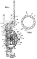
- the failsafe arrangement illustrated in the accompanying drawings is intended for use in monitoring the operation of a rotary actuator for use with a flap of an aircraft.
- the rotary actuator is driven by a drive shaft by a suitable motor, rotation of the drive shaft causing the flap to pivot about an axis.
- the speed of pivoting movement of the flap relative to the speed of rotation of the drive shaft is governed by a gearing arrangement contained within the actuator.
- the failsafe arrangement comprises a first mounting member 10 which is arranged to be secured to a fixed part of the aircraft and a second mounting member 11 which is angularly movable relative to the first mounting member and is intended to be secured, in use, to the flap.
- the first and second mounting members 10, 11 are each provided with cylindrical walls 10 a , 11 a which are presented towards one another and between which bearings 12 are provided to guide the second mounting member 11 for pivotal movement relative to the first mounting member 10.
- the first mounting member 10 is provided with a second, inwardly directed cylindrical surface 10 b of substantially circular cross-section which encircles a polygonal surface 11 b provided on an inwardly extending annular wall 11 c of the second mounting member 11.
- the second surface 10 b and polygonal surface 11 b define, therebetween, a channel 13 which, as illustrated most clearly in Figure 2, is of non-uniform width.
- a plurality of wedge members, which conveniently take the form of rollers 14, are located within the channel 13.
- the diameters of the rollers 14 are substantially equal to the maximum width of the channel 13, and as illustrated in Figure 2, the rollers 14 being located such that each roller lies approximately midway along each flat side of the polygonal surface 11 b .
- the rollers 14 are carried by a drive member 15 which is rotatable within a housing defined by the first and second mounting members 10, 11, the drive member 15 being supported for rotational movement relative to both the first and second mounting members 10, 11 by means of bearings 16.
- the drive member 15 is arranged to be driven for rotation within the housing defined by the first and second mounting members 10, 11 by an eccentric gear arrangement 17 including a plurality of gears 17 a , the gear arrangement 17 being arranged to be driven, in use, by an input shaft 18 which is driven by the drive shaft used to drive the actuator.
- the eccentric gear arrangement 17 is arranged to drive the drive member 15 such that angular movement of the drive member 15 occurs at the same speed as movement of the second mounting member 11 by the flap, for a given speed of rotation of the drive shaft.
- the wall 11 c is provided with a plurality of drillings within which additional wedge members, in the form of spherical members 19, are located, springs 20 being provided to bias the spherical members 19 into engagement with the drive member 15.
- the drive member 15 is provided with recesses or relatively small diameter drillings 21, the members 19 being biased into engagement with the drillings 21 by means of the springs 20. It will be appreciated, therefore, that the drive member 15 is lightly held against movement relative to the second mounting member 11.
- a pin 22 is provided in one of the drillings and is arranged to engage the associated member 19, the pin 22 being engageable with a pivotally mounted indicator flag or member 23 such that inward movement of the member 19, as would occur in the event that relative movement occurs between the drive member 15 and the second mounting member 11 forcing the member 19 out of the drilling 21, causes the pin 22 to push the indicator member 23 from a rest position to an actuated position.
- the indicator member 23 provides a visual indication of the presence of a condition in which relative movement of the drive member 15 and second mounting member 11 has occurred.
- the input shaft 18 is provided with a surface 18 a of polygonal form which is presented towards a cylindrical surface 24 a of a housing part 24 which is secured to the first mounting member 10.
- the surfaces 18 a , 24 a define therebetween a channel 25 of non-uniform width within which rollers 26 are located.
- the rollers 26 are held in positions substantially midway along respective sides of the polygonal surface 18 a by a second drive member 27 which, in normal use, is driven at substantially the same speed as the input shaft 18. This is achieved by mounting the second drive member 27 upon an input part 17 b of the eccentric gear arrangement 17 through a splined coupling.
- the input part 17 b of the eccentric gear arrangement 17 upon which the second drive member 27 is mounted is driven by the input shaft 18 through a ball/ramp drive arrangement 29 which comprises a plurality of balls or rollers located within recesses formed in the input shaft 18 and in a member 28 which is splined to the input part 17 b .
- the splined coupling between the member 28 and the input part 17 b allows limited axial movement of the member 28 to occur, the member 28 being moveable between a position in which the balls or rollers of the drive arrangement 29 are located within their respective recesses to transmit rotary movement of the input shaft 18 to the member 28, and a position in which the balls or rollers can ride out of the recesses so that drive is no longer transmitted to the member 28.
- a plate 30 is located between the second mounting member 11 and the first drive member 15, the plate 30 being biased towards the first drive member 15 by springs 31 and being arranged to rotate with the second mounting member 11.
- a roller/ramp arrangement 32 is provided between the plate 30 and the first drive member 15 such that, in the event of relative angular movement occurring between the first drive member 15 and the plate 30, as occurs in the event of angular movement occurring between the first drive member 15 and the second mounting member 11, axial movement of the plate 30 occurs.
- a coupling arrangement 33 which permits angular movement to occur between the plate 30 and the member 28 is provided to transmit such axial movement to the member 28.
- the rollers 14 and the rollers 26 are positioned by the first and second drive members 15, 27 such that the rollers 14, 26 lie generally midway along each side surface of the respective polygonal surface 11 b , 18 a . In these positions, the rollers do not inhibit relative rotation of the surfaces 10 b , 11 b or relative rotation between the surfaces 18 a , 24 a .
- first and second drive members 15, 27 move relative to the polygonal surfaces 11 b , 18 a to move the rollers 14, 26 away from the midway positions, then the rollers 14, 26 will act as wedges, preventing or impeding relative movement between the surfaces 10 b , 11 b and between the surfaces 18 a , 24 a .
- rotation of the drive shaft causes pivoting movement of the flap.
- the movement of the flap causes movement of the second mounting member 11 as the second mounting member 11 is secured thereto.
- a limited amount of relative movement between the flap and the second mounting member 11 may be permitted, if desired.
- the rotation of the drive shaft which causes the movement of the flap will also cause rotation of the input shaft 18.
- the rotation of the input shaft 18 causes angular movement of the first drive member 15 at the same speed as the second mounting member 11 and the flap are moved due to the eccentric gear arrangement 17.
- both the first drive member 15 and the associated rollers 14 and the second mounting member 11 will move angularly relative to the first mounting member 10.
- the rollers 14 are held in the positions illustrated in Figure 2 relative to the second surface 11 b , occupying their substantially midway positions along the side surfaces forming the second surface 11 b .
- the second drive member 27 will hold the rollers 26 in the midway positions along the sides defining the surface 18 a and rotation of the input shaft 18 relative to the housing 24 and first mounting member 10 will not be impeded.
- the failsafe arrangement of this embodiment employs an alternative technique for preventing rotation of the drive shaft as follows. Upon relative rotation occurring between the first drive member 15 and the second mounting member 11, and hence the plate 30, the roller and ramp arrangements 32 cause the plate 30 to move axially against the springs 31. This movement is transmitted through the coupling arrangement 33 to the member 28, moving the member 28 to a position in which the drive arrangement 29 disengages, relative angular movement then being permitted between the input shaft 18 and the member 28.
- both the flap and the input shaft are wedged against further movement. Additionally, upon the relative movement having occurred between the first drive member 15 and the second mounting member 11, the members 19 ride out of the recesses 21, causing movement of the pin 22 to push the indicator member 23 from its rest position to its deployed position, thus providing a visual indication of the presence of any faults.
Landscapes
- Engineering & Computer Science (AREA)
- General Engineering & Computer Science (AREA)
- Mechanical Engineering (AREA)
- Automation & Control Theory (AREA)
- Aviation & Aerospace Engineering (AREA)
- Transmission Devices (AREA)
Applications Claiming Priority (2)
| Application Number | Priority Date | Filing Date | Title |
|---|---|---|---|
| GBGB9914006.3A GB9914006D0 (en) | 1999-06-17 | 1999-06-17 | Failsafe arrangement |
| GB9914006 | 1999-06-17 |
Publications (2)
| Publication Number | Publication Date |
|---|---|
| EP1072507A1 true EP1072507A1 (de) | 2001-01-31 |
| EP1072507B1 EP1072507B1 (de) | 2004-09-15 |
Family
ID=10855456
Family Applications (1)
| Application Number | Title | Priority Date | Filing Date |
|---|---|---|---|
| EP00304972A Expired - Lifetime EP1072507B1 (de) | 1999-06-17 | 2000-06-13 | Ausfallsichere Anordnung |
Country Status (4)
| Country | Link |
|---|---|
| US (1) | US6616096B1 (de) |
| EP (1) | EP1072507B1 (de) |
| DE (1) | DE60013712T2 (de) |
| GB (1) | GB9914006D0 (de) |
Cited By (3)
| Publication number | Priority date | Publication date | Assignee | Title |
|---|---|---|---|---|
| FR2883346A1 (fr) * | 2005-03-21 | 2006-09-22 | Eurocopter France | Limiteur de couple a deux entrees mecaniques |
| WO2006093543A3 (en) * | 2004-11-23 | 2006-10-19 | Hr Textron Inc | Torque limitting device using detent members responsive to radial force |
| EP1955947A3 (de) * | 2006-10-06 | 2009-05-06 | Goodrich Actuation Systems Ltd. | Stellantrieb |
Families Citing this family (1)
| Publication number | Priority date | Publication date | Assignee | Title |
|---|---|---|---|---|
| DE10308301B3 (de) * | 2003-02-26 | 2004-07-15 | Liebherr-Aerospace Lindenberg Gmbh | Flugzeughochauftriebssystem mit Überlastsicherung |
Citations (5)
| Publication number | Priority date | Publication date | Assignee | Title |
|---|---|---|---|---|
| US3640092A (en) * | 1970-07-10 | 1972-02-08 | Hobson Ltd H M | Torque limiter |
| US4121795A (en) * | 1976-03-25 | 1978-10-24 | Lucas Industries Limited | Brake device for use in a remote actuation system |
| US4578993A (en) * | 1983-12-30 | 1986-04-01 | Sundstrand Corporation | Failure detection system for geared rotary actuator mechanism |
| US4901831A (en) * | 1987-10-09 | 1990-02-20 | Ntn Toyo Bearing Co., Ltd. | Clutch |
| US5016740A (en) * | 1988-07-14 | 1991-05-21 | Ntn Corporation | Torque responsive engaging clutch |
Family Cites Families (8)
| Publication number | Priority date | Publication date | Assignee | Title |
|---|---|---|---|---|
| US2500691A (en) * | 1945-01-22 | 1950-03-14 | Lear Inc | Mechanical actuator system |
| US3203275A (en) * | 1962-11-26 | 1965-08-31 | Vaino A Hoover | Mechanical actuator |
| US3701401A (en) * | 1971-05-12 | 1972-10-31 | Curtiss Wright Corp | Torque overload sensing and indicating device for torque limiting brake mechanism |
| US3802281A (en) * | 1972-10-26 | 1974-04-09 | Lucas Aerospace Ltd | Driving arrangements for leadscrews |
| US4688744A (en) * | 1982-09-03 | 1987-08-25 | Sundstrand Corporation | Jam tolerant rotary actuation system |
| US4742730A (en) * | 1982-09-30 | 1988-05-10 | The Boeing Company | Failsafe rotary actuator |
| US4691582A (en) * | 1984-01-30 | 1987-09-08 | Weyer Paul P | Thin profile rotary actuator with backlash elimination |
| GB2301394B (en) * | 1995-05-27 | 1998-09-02 | Philip Charles Shephard | Angular adjustment mechanisms |
-
1999
- 1999-06-17 GB GBGB9914006.3A patent/GB9914006D0/en not_active Ceased
-
2000
- 2000-06-13 DE DE60013712T patent/DE60013712T2/de not_active Expired - Lifetime
- 2000-06-13 EP EP00304972A patent/EP1072507B1/de not_active Expired - Lifetime
- 2000-06-16 US US09/595,412 patent/US6616096B1/en not_active Expired - Lifetime
Patent Citations (5)
| Publication number | Priority date | Publication date | Assignee | Title |
|---|---|---|---|---|
| US3640092A (en) * | 1970-07-10 | 1972-02-08 | Hobson Ltd H M | Torque limiter |
| US4121795A (en) * | 1976-03-25 | 1978-10-24 | Lucas Industries Limited | Brake device for use in a remote actuation system |
| US4578993A (en) * | 1983-12-30 | 1986-04-01 | Sundstrand Corporation | Failure detection system for geared rotary actuator mechanism |
| US4901831A (en) * | 1987-10-09 | 1990-02-20 | Ntn Toyo Bearing Co., Ltd. | Clutch |
| US5016740A (en) * | 1988-07-14 | 1991-05-21 | Ntn Corporation | Torque responsive engaging clutch |
Cited By (6)
| Publication number | Priority date | Publication date | Assignee | Title |
|---|---|---|---|---|
| WO2006093543A3 (en) * | 2004-11-23 | 2006-10-19 | Hr Textron Inc | Torque limitting device using detent members responsive to radial force |
| US7367891B2 (en) | 2004-11-23 | 2008-05-06 | Hr Textron, Inc. | Techniques for controlling transfer of torque using detent members responsive to radial force |
| FR2883346A1 (fr) * | 2005-03-21 | 2006-09-22 | Eurocopter France | Limiteur de couple a deux entrees mecaniques |
| EP1705115A1 (de) * | 2005-03-21 | 2006-09-27 | Eurocopter | Drehmomentbegrenzer mit zwei mechanischen Eingängen |
| US7520813B2 (en) | 2005-03-21 | 2009-04-21 | Eurocopter | Torque limiter having two mechanical inlets |
| EP1955947A3 (de) * | 2006-10-06 | 2009-05-06 | Goodrich Actuation Systems Ltd. | Stellantrieb |
Also Published As
| Publication number | Publication date |
|---|---|
| US6616096B1 (en) | 2003-09-09 |
| DE60013712D1 (de) | 2004-10-21 |
| EP1072507B1 (de) | 2004-09-15 |
| GB9914006D0 (en) | 1999-08-18 |
| DE60013712T2 (de) | 2005-09-29 |
Similar Documents
| Publication | Publication Date | Title |
|---|---|---|
| US7410132B1 (en) | Jam tolerant electromechanical actuation systems and methods of operation | |
| US8267350B2 (en) | Jam-tollerant actuator | |
| US8336818B2 (en) | Jam tolerant electromechanical actuation systems and methods of operation | |
| US8336817B2 (en) | Jam tolerant electromechanical actuation systems and methods of operation | |
| EP1955947A2 (de) | Stellantrieb | |
| US5655636A (en) | Compact actuator including resettable force limiting and anti-backdrive devices | |
| EP1378685A2 (de) | Anti-Rückwärts Vorrichtung | |
| US8511441B2 (en) | Cone brake no-back | |
| EP3339685B1 (de) | Aktuator | |
| DE102009037106A1 (de) | Asymmetrische Bremse mit großer Verstärkung | |
| US4628752A (en) | Actuators and actuator assemblies | |
| US20140135132A1 (en) | Non-chattering ball detent torque limiter | |
| US7367891B2 (en) | Techniques for controlling transfer of torque using detent members responsive to radial force | |
| US6237433B1 (en) | Electromechanical actuator of the type having a screw-and-nut system | |
| JP4102660B2 (ja) | 差動トルク制限器 | |
| EP1310699A2 (de) | Drehantrieb | |
| US6616096B1 (en) | Failsafe arrangement | |
| JPH0833168B2 (ja) | 非故障の機械的回転作動器 | |
| EP1308645A1 (de) | Kugelspindelantrieb für ein Luftfahrzeug | |
| US11719339B2 (en) | Low drag torque limiter for electric TRAS | |
| EP3219610B1 (de) | Rückstossvorbeugungsvorrichtung und zugehöriges verfahren | |
| JP2025530493A (ja) | 線形アクチュエータ | |
| JPH0694052A (ja) | 船外機の安全装置 |
Legal Events
| Date | Code | Title | Description |
|---|---|---|---|
| PUAI | Public reference made under article 153(3) epc to a published international application that has entered the european phase |
Free format text: ORIGINAL CODE: 0009012 |
|
| AK | Designated contracting states |
Kind code of ref document: A1 Designated state(s): DE ES FR GB IT |
|
| AX | Request for extension of the european patent |
Free format text: AL;LT;LV;MK;RO;SI |
|
| 17P | Request for examination filed |
Effective date: 20010702 |
|
| 17Q | First examination report despatched |
Effective date: 20010823 |
|
| AKX | Designation fees paid |
Free format text: DE ES FR GB IT |
|
| RAP1 | Party data changed (applicant data changed or rights of an application transferred) |
Owner name: LUCAS INDUSTRIES LIMITED |
|
| RAP1 | Party data changed (applicant data changed or rights of an application transferred) |
Owner name: GOODRICH ACTUATION SYSTEMS LTD |
|
| GRAP | Despatch of communication of intention to grant a patent |
Free format text: ORIGINAL CODE: EPIDOSNIGR1 |
|
| GRAS | Grant fee paid |
Free format text: ORIGINAL CODE: EPIDOSNIGR3 |
|
| GRAA | (expected) grant |
Free format text: ORIGINAL CODE: 0009210 |
|
| AK | Designated contracting states |
Kind code of ref document: B1 Designated state(s): DE ES FR GB IT |
|
| PG25 | Lapsed in a contracting state [announced via postgrant information from national office to epo] |
Ref country code: IT Free format text: LAPSE BECAUSE OF FAILURE TO SUBMIT A TRANSLATION OF THE DESCRIPTION OR TO PAY THE FEE WITHIN THE PRESCRIBED TIME-LIMIT;WARNING: LAPSES OF ITALIAN PATENTS WITH EFFECTIVE DATE BEFORE 2007 MAY HAVE OCCURRED AT ANY TIME BEFORE 2007. THE CORRECT EFFECTIVE DATE MAY BE DIFFERENT FROM THE ONE RECORDED. Effective date: 20040915 |
|
| REG | Reference to a national code |
Ref country code: GB Ref legal event code: FG4D |
|
| REF | Corresponds to: |
Ref document number: 60013712 Country of ref document: DE Date of ref document: 20041021 Kind code of ref document: P |
|
| PG25 | Lapsed in a contracting state [announced via postgrant information from national office to epo] |
Ref country code: ES Free format text: LAPSE BECAUSE OF FAILURE TO SUBMIT A TRANSLATION OF THE DESCRIPTION OR TO PAY THE FEE WITHIN THE PRESCRIBED TIME-LIMIT Effective date: 20041226 |
|
| PLBE | No opposition filed within time limit |
Free format text: ORIGINAL CODE: 0009261 |
|
| STAA | Information on the status of an ep patent application or granted ep patent |
Free format text: STATUS: NO OPPOSITION FILED WITHIN TIME LIMIT |
|
| ET | Fr: translation filed | ||
| 26N | No opposition filed |
Effective date: 20050616 |
|
| REG | Reference to a national code |
Ref country code: FR Ref legal event code: PLFP Year of fee payment: 17 |
|
| REG | Reference to a national code |
Ref country code: FR Ref legal event code: PLFP Year of fee payment: 18 |
|
| REG | Reference to a national code |
Ref country code: FR Ref legal event code: PLFP Year of fee payment: 19 |
|
| PGFP | Annual fee paid to national office [announced via postgrant information from national office to epo] |
Ref country code: DE Payment date: 20190521 Year of fee payment: 20 |
|
| PGFP | Annual fee paid to national office [announced via postgrant information from national office to epo] |
Ref country code: FR Payment date: 20190522 Year of fee payment: 20 |
|
| PGFP | Annual fee paid to national office [announced via postgrant information from national office to epo] |
Ref country code: GB Payment date: 20190522 Year of fee payment: 20 |
|
| REG | Reference to a national code |
Ref country code: DE Ref legal event code: R071 Ref document number: 60013712 Country of ref document: DE |
|
| REG | Reference to a national code |
Ref country code: GB Ref legal event code: PE20 Expiry date: 20200612 |
|
| PG25 | Lapsed in a contracting state [announced via postgrant information from national office to epo] |
Ref country code: GB Free format text: LAPSE BECAUSE OF EXPIRATION OF PROTECTION Effective date: 20200612 |