EP1074337A1 - Vorrichtung zum Antreiben und Dämpfen von Teleskopabdeckungen - Google Patents
Vorrichtung zum Antreiben und Dämpfen von Teleskopabdeckungen Download PDFInfo
- Publication number
- EP1074337A1 EP1074337A1 EP00830526A EP00830526A EP1074337A1 EP 1074337 A1 EP1074337 A1 EP 1074337A1 EP 00830526 A EP00830526 A EP 00830526A EP 00830526 A EP00830526 A EP 00830526A EP 1074337 A1 EP1074337 A1 EP 1074337A1
- Authority
- EP
- European Patent Office
- Prior art keywords
- box
- spring
- rod
- shaped
- shaped element
- Prior art date
- Legal status (The legal status is an assumption and is not a legal conclusion. Google has not performed a legal analysis and makes no representation as to the accuracy of the status listed.)
- Granted
Links
Images


Classifications
-
- B—PERFORMING OPERATIONS; TRANSPORTING
- B23—MACHINE TOOLS; METAL-WORKING NOT OTHERWISE PROVIDED FOR
- B23Q—DETAILS, COMPONENTS, OR ACCESSORIES FOR MACHINE TOOLS, e.g. ARRANGEMENTS FOR COPYING OR CONTROLLING; MACHINE TOOLS IN GENERAL CHARACTERISED BY THE CONSTRUCTION OF PARTICULAR DETAILS OR COMPONENTS; COMBINATIONS OR ASSOCIATIONS OF METAL-WORKING MACHINES, NOT DIRECTED TO A PARTICULAR RESULT
- B23Q11/00—Accessories fitted to machine tools for keeping tools or parts of the machine in good working condition or for cooling work; Safety devices specially combined with or arranged in, or specially adapted for use in connection with, machine tools
- B23Q11/08—Protective coverings for parts of machine tools; Splash guards
- B23Q11/0825—Relatively slidable coverings, e.g. telescopic
-
- B—PERFORMING OPERATIONS; TRANSPORTING
- B23—MACHINE TOOLS; METAL-WORKING NOT OTHERWISE PROVIDED FOR
- B23Q—DETAILS, COMPONENTS, OR ACCESSORIES FOR MACHINE TOOLS, e.g. ARRANGEMENTS FOR COPYING OR CONTROLLING; MACHINE TOOLS IN GENERAL CHARACTERISED BY THE CONSTRUCTION OF PARTICULAR DETAILS OR COMPONENTS; COMBINATIONS OR ASSOCIATIONS OF METAL-WORKING MACHINES, NOT DIRECTED TO A PARTICULAR RESULT
- B23Q11/00—Accessories fitted to machine tools for keeping tools or parts of the machine in good working condition or for cooling work; Safety devices specially combined with or arranged in, or specially adapted for use in connection with, machine tools
- B23Q11/08—Protective coverings for parts of machine tools; Splash guards
- B23Q2011/0808—Means for maintaining identical distances between relatively movable cover parts
Definitions
- the present invention relates to a device for driving and damping telescopic guards of the type consisting of a plurality of box-shaped elements.
- Guards of this kind are used mainly to protect the slideways of automatic machines, machine tools and robotised system by preventing dirt, chippings, swarf and machining emulsions from getting into and clogging up the contact areas of the slideways.
- the box-shaped elements are fitted with scrapers, usually, made of an elastomer or plastic material. These scrapers, besides keeping dirt and other foreign matter out of the gaps between adjacent box-shaped elements, also permit the achievement of a satisfactory seal.
- the box-shaped elements Since the guard is connected to the moving part of the machine, the box-shaped elements extend and retract at the same speed as that at which the machine moves. This speed can be very high and considering their size and weight, the box-shaped elements, when they reach the fully extended position, knock against each other with considerable force. Such shocks must obviously be avoided not only because of the wear and eventual damage they cause to the guard but also to prevent counterblows on the moving machine parts and, last but not least, to reduce noise.
- damping device designed for this purpose is described in utility model patent publication DE-U-7137781.
- the damping device is made by simply applying to the back of the scraper, where it comes into contact with the smaller, adjacent box-shaped element a strip of synthetic cellular material.
- Another type of damping device for the box-shaped elements of a telescopic guard made from a strip of material different from that of the scraper is described in patent publication EP-B-290822.
- the box-shaped elements stop, passing from a very high speed to zero speed in a very short space of time. They are therefore subjected to a high deceleration rate which can have negative effects on the moving machine parts.
- Italian patent No.012862248 in the name of the same Applicant as the present, describes a damping device equipped with deformable, elastic arms designed to damp the impact between two adjacent box-shaped elements when these are being extended.
- the principal aim of the present invention is to overcome the disadvantages of prior art through a new device for driving and damping the box-shaped elements of telescopic guides that is capable of simultaneously driving all the box-shaped elements while providing a gradual and effective damping action and that is simple and economical to make.
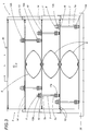
- the numeral 20 indicates as a whole a device for driving and damping a telescopic guard, labelled 1 as a whole, used to protect the slideways of automatic machines, machine tools and robotised systems, of known type and therefore not illustrated.
- the telescopic guard 1 comprising a plurality of box-shaped elements 2, is attached at one end to a fixed part 30 of the machine and, at the other end, to a moving part 40 of the machine, and can be extended or retracted in the direction of the arrow F.
- the box-shaped elements 2 making up the guard are of known type made, for example, of steel, and usually have at least one horizontal wall 2a, two vertical walls 2b, a front edge 2c and a rear edge 2d.
- each element 2 borders on two other box-shaped elements, one larger and the other smaller than it.
- the elements 2 slide inside one another in telescopic fashion in a direction F, moving between a first position in which the guard 1 is closed or fully retracted, to a second position in which the guard 1 is open or fully extended.
- These end positions of the telescopic guard 1 correspond to the end positions of the machine which the guard 1 is fitted to.
- each box-shaped element 2 Close to the rear edge 2d of each box-shaped element 2, there is a scraping device 3 comprising a section 4 and a scraping element 5, both of known type.
- each box-shaped element 2 is connected to the box-shaped element 2 adjacent to it by an elastic element, labelled 6 as a whole, fitted close to the rear edge 2d of each box-shaped element 2.
- the elastic elements 6 consist of leaf springs 61.
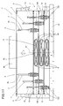
- two guide rods 7 connect each box-shaped element 2 to the box-shaped element 2 adjacent to it.
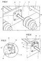
- a first end 7a of each rod 7 is rigidly connected to a box-shaped element 2, while a second end 7b has a stop surface 8.
- the latter is made in such a way that it engages with the smaller adjacent box-shaped element 2 to determine a fully extended position of the two box-shaped elements 2 relative to each other.
- the bush 9 has a friction element 10 consisting, for example, of a part 11 made of synthetic or natural rubber or of another material with a high abrasion resistance.
- each rod 7 is provided with damping means 12.
- damping means 12 comprise a first circular bellows 12a fitted round the rod 7 close to its first end 7a and a second circular bellows 12b fitted close to the second end 7b of the rod 7.
- the circular bellows 12a and 12b are made of synthetic material and are fitted in such a way that they can slide freely along part of the rod 7, on opposite sides of the rear edge 2d of the box-shaped element 2 crossed by the rod 7.
- the rods 7 of the different box-shaped elements 2 are offset from each other crossways so as not to interfere with each other during the opening and closing movements of the guard 1.
- Each box-shaped element 2 is equipped with rolling-contact bearings 13 fitted on the edge 2d, close to the ends of the edge 2d itself, which are designed to support the telescopic guard 1 and enable it to run on the slideways of the machine, which are not illustrated.
- each box-shaped element 2 also has a plurality of holes 14 allowing the passage of the rods 7 of the box-shaped elements 2 larger than it so that the size of the telescopic guard 1 when it is fully retracted, that is to say, closed, is not determined by the length of the rods 7 but by the space occupied by the leaf springs 61 lengthways when they are flat against each other.
- the elastic element 6 that connects the adjacent box-shaped elements 2 consists of a plastic spring 62 comprising a main body 63 made and designed to operate, at least during the opening of the box-shaped elements 2, like a pair of ordinary leaf springs positioned with their concave portions facing each other, and two eyes 64 forming an integral part of the body 63 and extending from both ends of the body 63 on opposite sides of an axis of symmetry A of the body 63 itself parallel to the above mentioned direction F.
- the eyes 64 constitute shock absorbing elements that come into operation by compression when the box-shaped elements 2 of the guard 1 are retracted.
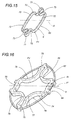
- the elastic connecting element 6, illustrated in more detail in Figure 15, consists of an annular spring 65 formed by a substantially rectangular plastic section 70, with a continuous preformed profile P1 and an axis of symmetry A', and consisting of two semicircular portions 71 with convexity facing the inside of the profile P1 and positioned on opposite sides of the axis of symmetry A', and two substantially straight portions 72, positioned across the above mentioned axis of symmetry A', and designed to be attached to the rear edges 2d of two adjacent box-shaped elements 2.
- the semicircular portions 71 are joined to the respective straight portions 72 by portions 73 curved in the shape of an S with concavities alternately facing the inside and outside of the annular spring 65 itself.
- each of the elastic elements 6 connecting adjacent box-shaped elements 2, illustrated in more detail in Figure 16 consists of a composite spring 66 made by assembling an annular spring 74 similar to the one described above, labelled 65 in Figures 9, 10 and 15, and a helical metal spring 67 closed in a loop round the annular spring 74 itself and forming a boundary P2 whose shape varies according to the movements of the box-shaped elements 2 relative to each other and inside which the annular spring 74 is inscribed.
- the annular spring 74 is formed by a substantially rectangular plastic section 77, with a continuous preformed profile P2 and an axis of symmetry A", and consisting of two semicircular portions 75 with convexity facing the inside of the profile P2 and positioned on opposite sides of the axis of symmetry A", and two substantially straight portions 76, which are shorter than the above mentioned straight portions 72 of the spring 65, said portions 76 being positioned opposite each other across the above mentioned axis of symmetry A", and designed to be attached to the rear edges 2d of two adjacent box-shaped elements 2.
- the semicircular portions 75 are joined to the respective straight portions 76 by portions 78 curved in the shape of a C with concavity facing the outside of the annular spring 74 itself.
- the helical spring 67 and the plastic spring 65, together forming the composite spring 66 are joined together at two or more points in such a way that their actions are combined during the movements of the box-shaped elements 2 relative to each other.
- These connecting points consist of blocks extending from the outer surface of the annular spring and each having a hole in it through which the helical spring 67 can pass.
- the elastic connecting elements 6 consist of leaf springs 68, each comprising two curved arms 69 whose concave portions face each other and which are hinged to each other at each end, the ends of the arms 69 being connected by a helical spring 67 providing additional spring action during the movements of the box-shaped elements 2 relative to each other.
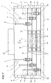
- the box-shaped elements 2 are retracted and almost entirely nested inside each other.
- the box-shaped elements 2 slide relative to each other on appropriate shoes (not illustrated).
- the elastic elements 6 are at least partly compressed so that when the moving part 40 of the automatic machine, machine tool or robotised system starts moving, the box-shaped element 2 to which the moving part 40 is connected is dragged along with it and the telescopic guard 1 thus starts opening, the opening action being facilitated also by the simultaneous extension of the elastic elements 6.
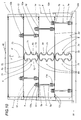
- the elastic elements 6 cause all the box-shaped elements 2 to which they are connected to be simultaneously extended in the direction of the arrow F.
- Figure 3 illustrates four box-shaped elements 2 in an almost fully extended position.
- the circular bellows 12b placed between the stop surface 8 and the bush 9 provides an effective damping action thanks not only to the compression of the air inside it but also to the shape of the bellows 12b and the material it is made of. Therefore, when the telescopic guard 1 is extended, the box-shaped elements 2 are prevented from knocking against each other.
- each of the elastic elements 6 is stretched and thus has a certain amount of accumulated elastic potential energy.
- This elastic energy is returned by the elastic elements 6 to the box-shaped elements 2 from the moment the guard starts retracting again following the motion of the moving part 40 of the machine.
- the return action exerted by the elastic elements 6 during the reclosing movement tends to move the box-shaped elements 2 towards each other again.
- the compression of the bellows 12a provides an effective damping action which prevents the box-shaped elements 2 from knocking against each other.
- the elastic elements 6 contribute to the damping action by compressing and thus absorbing, in the form of elastic potential energy, part of the kinetic energy possessed by the box-shaped elements 2 as they move towards each other, accumulating this energy so that it can be used later, when the telescopic guard 1 next opens.
- the damping capability of the device is much higher than that of known devices of this kind.
- the damping action is developed gradually and effectively over a relatively long stroke.
- the friction element 10 comprises a pressure element 16, actuated by a spring 17 and acting on the part 11 in such a way as to push it against the rod 7.
- the contact pressure between the part 11 and the surface of the rod 7 generates a friction component which opposes the relative motion between the rod 7 itself and the different parts attached to the friction element 10.
- the contact pressure between the part 11 and the rod can be adjusted using a screw 18 which controls the thrust force of the spring 17.
- the friction element 10 acting on the rods 7 has a stabilising effect on the telescopic guard 1, thus preventing vibrations, at both high and low speeds of the box-shaped elements 2 retracting and extending relative to each other.
- the drive and damping device 20 disclosed by the present invention further comprises a damping element 15 made of plastic and fitted to the rear edge 2d of each box-shaped element 2 at the corner between the horizontal wall 2a and the vertical wall 2b of the element 2.
- the device 15 has a lightening groove 15a extending lengthways parallel to the side of the guard.
Landscapes
- Engineering & Computer Science (AREA)
- Mechanical Engineering (AREA)
- Vibration Dampers (AREA)
- Details Of Aerials (AREA)
- Buffer Packaging (AREA)
- Vibration Prevention Devices (AREA)
- Helmets And Other Head Coverings (AREA)
Applications Claiming Priority (2)
| Application Number | Priority Date | Filing Date | Title |
|---|---|---|---|
| ITBO990436 | 1999-07-30 | ||
| IT1999BO000436A IT1310285B1 (it) | 1999-07-30 | 1999-07-30 | Dispositivo di movimentazione e ammortizzamento per protezioniteloscopiche. |
Publications (2)
| Publication Number | Publication Date |
|---|---|
| EP1074337A1 true EP1074337A1 (de) | 2001-02-07 |
| EP1074337B1 EP1074337B1 (de) | 2003-11-12 |
Family
ID=11344165
Family Applications (1)
| Application Number | Title | Priority Date | Filing Date |
|---|---|---|---|
| EP00830526A Expired - Lifetime EP1074337B1 (de) | 1999-07-30 | 2000-07-25 | Vorrichtung zum Antreiben und Dämpfen von Teleskopabdeckungen |
Country Status (6)
| Country | Link |
|---|---|
| US (1) | US6431249B1 (de) |
| EP (1) | EP1074337B1 (de) |
| AT (1) | ATE254009T1 (de) |
| DE (1) | DE60006458T2 (de) |
| ES (1) | ES2209800T3 (de) |
| IT (1) | IT1310285B1 (de) |
Cited By (7)
| Publication number | Priority date | Publication date | Assignee | Title |
|---|---|---|---|---|
| US6422290B1 (en) * | 1999-04-30 | 2002-07-23 | P.E.I. Protezioni Elaborazioni Industriali S.R.L. | Damping device for telescopic guards |
| EP1245213A3 (de) * | 2001-03-27 | 2003-07-16 | GE Medical Systems Global Technology Company LLC | Verfahren und Vorrichtung zur Abdeckung eines verstellbaren Patiententisches |
| EP1253369A3 (de) * | 2001-04-27 | 2003-12-17 | P.E.I. Protezioni Elaborazioni Industriali S.r.l. | Schutzabdeckung für eine Maschine und Ausrüstung |
| EP1452268A1 (de) * | 2003-02-25 | 2004-09-01 | Hennig Holding GmbH | Teleskop-Abdeckung |
| WO2007031112A1 (de) * | 2005-09-12 | 2007-03-22 | Möller Werke GmbH | Schutzabdeckung und stabilisierungselement hierfür |
| ITBO20110376A1 (it) * | 2011-06-28 | 2012-12-29 | P E I Protezioni Elaborazioniindus Triali S R L | Dispositivo attuatore per protezioni telescopiche |
| EP2708319A1 (de) * | 2012-09-17 | 2014-03-19 | P.E.I. Protezioni Elaborazioni Industriali S.r.l. | Stellgliedvorrichtung für ausfahrbaren Schutz |
Families Citing this family (17)
| Publication number | Priority date | Publication date | Assignee | Title |
|---|---|---|---|---|
| ITBO20010048A1 (it) * | 2001-01-31 | 2002-07-31 | Pei Protezioni Elaborazioni | Dispositivo di collegamento per lamelle di protezione di un soffiettodi copertura di guide du macchine automatiche, macchine utensili e rob |
| JP3944199B2 (ja) * | 2003-10-16 | 2007-07-11 | ファナック株式会社 | テレスコピックカバー |
| US7458754B2 (en) * | 2006-11-14 | 2008-12-02 | Hardinge Taiwan Ltd. | Telescopic covering device for machine tool |
| ITBO20120099A1 (it) | 2012-02-29 | 2013-08-30 | Pei Protezioni Elaborazioni | Dispositivo raschiatore. |
| US9089087B2 (en) | 2012-04-19 | 2015-07-28 | Wirtgen Gmbh | Runner segment for an edge guard of a road milling machine, and edge guard for a road milling machine |
| JP5964189B2 (ja) * | 2012-09-24 | 2016-08-03 | オークマ株式会社 | 摺動面保護装置 |
| DE102014102330A1 (de) * | 2014-02-24 | 2015-08-27 | ThyssenKrupp Federn und Stabilisatoren GmbH | Tragfedereinheit für ein Fahrzeugfahrwerk |
| JP6639794B2 (ja) * | 2015-03-24 | 2020-02-05 | 住友重機械工業株式会社 | スライドカバー |
| DE102015119376A1 (de) * | 2015-11-10 | 2017-05-11 | Eitec Führungsbahnschutz-Systeme Gmbh | Teleskopabdeckung |
| JP6457450B2 (ja) | 2016-09-05 | 2019-01-23 | ファナック株式会社 | スライドテーブル装置 |
| DE102016123662A1 (de) | 2016-12-07 | 2018-06-07 | Wirtgen Gmbh | Kufensegment für einen Kantenschutz einer Straßenfräsmaschine und Kantenschutz für eine Straßenfräsmaschine |
| JP6542845B2 (ja) * | 2017-07-14 | 2019-07-10 | ファナック株式会社 | テレスコピックカバー及び工作機械 |
| AU201810959S (en) | 2017-08-25 | 2018-03-07 | Wirtgen Gmbh | Milling machine part |
| DE202018106055U1 (de) * | 2018-10-23 | 2020-01-24 | Igus Gmbh | Teleskopabdeckung für eine Werkzeugmaschine |
| JP6969833B1 (ja) * | 2021-07-07 | 2021-11-24 | 株式会社ジャバラ | テレスコピックカバー |
| JP7032841B1 (ja) * | 2021-10-06 | 2022-03-09 | 株式会社ジャバラ | テレスコピックカバー |
| DE102024130810A1 (de) * | 2024-10-22 | 2026-04-23 | MöllerWerke GmbH | Schutzabdeckung und Verwendung eines Federelements |
Citations (3)
| Publication number | Priority date | Publication date | Assignee | Title |
|---|---|---|---|---|
| DE1262735B (de) * | 1957-01-04 | 1968-03-07 | Arnold Hennig | Zum Schutz der Fuehrungsbahn hin- und hergehender Teile von Werkzeugmaschinen dienende Abdeckung aus teleskopartig ineinander schiebbaren Kaesten |
| US3565153A (en) * | 1967-03-04 | 1971-02-23 | Kabelschbepp Gmbh | Protective cover for guide paths of machine tools |
| US4039021A (en) * | 1974-11-12 | 1977-08-02 | Kabelschlepp Gesellschaft Mit Beschrankter Haftung | Protective cover for guiding paths of machine tools |
Family Cites Families (19)
| Publication number | Priority date | Publication date | Assignee | Title |
|---|---|---|---|---|
| US3437367A (en) * | 1967-02-27 | 1969-04-08 | Stewart M Blank | Deformed shock absorbing devices |
| FR1576930A (de) * | 1967-12-14 | 1969-08-01 | ||
| GB1164570A (en) * | 1967-12-21 | 1969-09-17 | Kabelschlepp Gmbh | Improvements in or relating to Covers for the Slideways of Machine Tools |
| US3664653A (en) * | 1969-12-29 | 1972-05-23 | Brooks Walker | Energy absorber |
| US3784181A (en) * | 1972-05-05 | 1974-01-08 | Gen Tire & Rubber Co | Energy absorbing buckling box |
| US4362148A (en) * | 1980-06-30 | 1982-12-07 | Alco Standard Corporation | Cooking device with cover locking means |
| JPS5863673A (ja) * | 1981-10-08 | 1983-04-15 | 三菱電機株式会社 | エレベ−タ用緩衝装置 |
| US4583716A (en) * | 1982-05-19 | 1986-04-22 | Energy Absorption Systems, Inc. | Universal anchor assembly for impact attenuation device |
| EP0290822B1 (de) | 1987-05-13 | 1991-07-24 | Gebr. Hennig GmbH | Abstreifeinrichtung |
| US5199926A (en) * | 1988-04-11 | 1993-04-06 | Gebr. Hennig Gmbh | Telescopic cover |
| US4881891A (en) * | 1989-01-11 | 1989-11-21 | Triangle Tool Corporation | Mold side wall locking apparatus |
| US4962916A (en) * | 1989-11-17 | 1990-10-16 | Uniroyal Chemical Company, Inc. | Compression spring |
| US4997171A (en) * | 1989-12-15 | 1991-03-05 | Miner Elastomer Products Corporation | Heavy off-road large vehicle suspension strut |
| US5224689A (en) * | 1991-12-16 | 1993-07-06 | Jordan Valchev Georgiev | Shock absorbing device allowing reducing the vehicle weight |
| DE4403127C2 (de) * | 1993-08-04 | 1998-01-22 | Mannesmann Sachs Ag | Pralldämpfer mit Deformationskörper |
| FR2742519B1 (fr) * | 1995-12-19 | 1998-03-06 | Renault Automation | Tablier de protection telescopique pour accompagner les evolutions d'un organe mobile |
| US6082716A (en) * | 1996-09-30 | 2000-07-04 | P.E.I. Protezioni Elaborazioni Industriali, S.R.L. | Shock absorber device for telescopic protection devices |
| US6193460B1 (en) * | 1997-03-20 | 2001-02-27 | Robert J. Damico | Extendible rear bumper for an extendible tilt bed roll off truck |
| US5884684A (en) * | 1998-07-16 | 1999-03-23 | Jefferson; Samuel Alexander | Telescopic sun screen assembly |
-
1999
- 1999-07-30 IT IT1999BO000436A patent/IT1310285B1/it active
-
2000
- 2000-07-25 AT AT00830526T patent/ATE254009T1/de not_active IP Right Cessation
- 2000-07-25 ES ES00830526T patent/ES2209800T3/es not_active Expired - Lifetime
- 2000-07-25 DE DE60006458T patent/DE60006458T2/de not_active Expired - Fee Related
- 2000-07-25 EP EP00830526A patent/EP1074337B1/de not_active Expired - Lifetime
- 2000-07-27 US US09/626,988 patent/US6431249B1/en not_active Expired - Fee Related
Patent Citations (3)
| Publication number | Priority date | Publication date | Assignee | Title |
|---|---|---|---|---|
| DE1262735B (de) * | 1957-01-04 | 1968-03-07 | Arnold Hennig | Zum Schutz der Fuehrungsbahn hin- und hergehender Teile von Werkzeugmaschinen dienende Abdeckung aus teleskopartig ineinander schiebbaren Kaesten |
| US3565153A (en) * | 1967-03-04 | 1971-02-23 | Kabelschbepp Gmbh | Protective cover for guide paths of machine tools |
| US4039021A (en) * | 1974-11-12 | 1977-08-02 | Kabelschlepp Gesellschaft Mit Beschrankter Haftung | Protective cover for guiding paths of machine tools |
Cited By (7)
| Publication number | Priority date | Publication date | Assignee | Title |
|---|---|---|---|---|
| US6422290B1 (en) * | 1999-04-30 | 2002-07-23 | P.E.I. Protezioni Elaborazioni Industriali S.R.L. | Damping device for telescopic guards |
| EP1245213A3 (de) * | 2001-03-27 | 2003-07-16 | GE Medical Systems Global Technology Company LLC | Verfahren und Vorrichtung zur Abdeckung eines verstellbaren Patiententisches |
| EP1253369A3 (de) * | 2001-04-27 | 2003-12-17 | P.E.I. Protezioni Elaborazioni Industriali S.r.l. | Schutzabdeckung für eine Maschine und Ausrüstung |
| EP1452268A1 (de) * | 2003-02-25 | 2004-09-01 | Hennig Holding GmbH | Teleskop-Abdeckung |
| WO2007031112A1 (de) * | 2005-09-12 | 2007-03-22 | Möller Werke GmbH | Schutzabdeckung und stabilisierungselement hierfür |
| ITBO20110376A1 (it) * | 2011-06-28 | 2012-12-29 | P E I Protezioni Elaborazioniindus Triali S R L | Dispositivo attuatore per protezioni telescopiche |
| EP2708319A1 (de) * | 2012-09-17 | 2014-03-19 | P.E.I. Protezioni Elaborazioni Industriali S.r.l. | Stellgliedvorrichtung für ausfahrbaren Schutz |
Also Published As
| Publication number | Publication date |
|---|---|
| ITBO990436A1 (it) | 2001-01-30 |
| DE60006458T2 (de) | 2004-09-09 |
| IT1310285B1 (it) | 2002-02-11 |
| EP1074337B1 (de) | 2003-11-12 |
| ATE254009T1 (de) | 2003-11-15 |
| DE60006458D1 (de) | 2003-12-18 |
| US6431249B1 (en) | 2002-08-13 |
| ITBO990436A0 (it) | 1999-07-30 |
| ES2209800T3 (es) | 2004-07-01 |
Similar Documents
| Publication | Publication Date | Title |
|---|---|---|
| US6431249B1 (en) | Device for damping movement of telescopic guards | |
| CA1285003C (en) | Synthetic absorber for bumpers | |
| JP6998380B2 (ja) | ベルトコンベヤのスクレーパシステム | |
| US6422290B1 (en) | Damping device for telescopic guards | |
| EP0832715B1 (de) | Stossdämpfervorrichtung für teleskopartige Schutzvorrichtung | |
| US4039021A (en) | Protective cover for guiding paths of machine tools | |
| US6446397B1 (en) | Telescoping cover bumper | |
| US6082716A (en) | Shock absorber device for telescopic protection devices | |
| CA1148108A (en) | Apparatus for stopping articles on a conveyor | |
| EP2882569B1 (de) | Teleskopische schutzabdeckung | |
| CN114310861B (zh) | 一种基于智能制造用机械手 | |
| US6481313B1 (en) | Protective cover attachable to a working part which is mobile in at least one plane | |
| CN108715191A (zh) | 一种履带驱动轮 | |
| CA2075759C (en) | Piston compressor for the oilfree compression of a gas | |
| EP1410876B1 (de) | Teleskopabdeckung insbesondere für Werkzeugmaschine | |
| EP2708319B1 (de) | Stellgliedvorrichtung für ausfahrbaren Schutz | |
| ITCR20010005A1 (it) | Dispositivo ammortizzatore a doppio effetto per coperture telescopiche | |
| CN117249147B (zh) | 一种防冲击平衡型液压油缸 | |
| CN208787173U (zh) | 一种机械设备防尘装置 | |
| KR101054181B1 (ko) | 세탁기의 댐퍼 구조 | |
| CN217898348U (zh) | 一种设有防碰撞结构的液压油缸 | |
| SU905452A1 (ru) | Исполнительный орган струга | |
| CN222227243U (zh) | 一种可聚拢水面漂浮物的收集装置 | |
| CN213576159U (zh) | 飞行器专用补偿器 | |
| ITMI20030130U1 (it) | Ammortizzatore idraulico specialmente per parti mobili di mobili |
Legal Events
| Date | Code | Title | Description |
|---|---|---|---|
| PUAI | Public reference made under article 153(3) epc to a published international application that has entered the european phase |
Free format text: ORIGINAL CODE: 0009012 |
|
| AK | Designated contracting states |
Kind code of ref document: A1 Designated state(s): AT BE CH CY DE DK ES FI FR GB GR IE IT LI LU MC NL PT SE |
|
| AX | Request for extension of the european patent |
Free format text: AL;LT;LV;MK;RO;SI |
|
| 17P | Request for examination filed |
Effective date: 20010312 |
|
| AKX | Designation fees paid |
Free format text: AT BE CH CY DE DK ES FI FR GB GR IE IT LI LU MC NL PT SE |
|
| 17Q | First examination report despatched |
Effective date: 20020809 |
|
| GRAH | Despatch of communication of intention to grant a patent |
Free format text: ORIGINAL CODE: EPIDOS IGRA |
|
| GRAH | Despatch of communication of intention to grant a patent |
Free format text: ORIGINAL CODE: EPIDOS IGRA |
|
| GRAA | (expected) grant |
Free format text: ORIGINAL CODE: 0009210 |
|
| AK | Designated contracting states |
Kind code of ref document: B1 Designated state(s): AT BE CH CY DE DK ES FI FR GB GR IE IT LI LU MC NL PT SE |
|
| PG25 | Lapsed in a contracting state [announced via postgrant information from national office to epo] |
Ref country code: FI Free format text: LAPSE BECAUSE OF FAILURE TO SUBMIT A TRANSLATION OF THE DESCRIPTION OR TO PAY THE FEE WITHIN THE PRESCRIBED TIME-LIMIT Effective date: 20031112 Ref country code: AT Free format text: LAPSE BECAUSE OF FAILURE TO SUBMIT A TRANSLATION OF THE DESCRIPTION OR TO PAY THE FEE WITHIN THE PRESCRIBED TIME-LIMIT Effective date: 20031112 Ref country code: NL Free format text: LAPSE BECAUSE OF FAILURE TO SUBMIT A TRANSLATION OF THE DESCRIPTION OR TO PAY THE FEE WITHIN THE PRESCRIBED TIME-LIMIT Effective date: 20031112 Ref country code: BE Free format text: LAPSE BECAUSE OF FAILURE TO SUBMIT A TRANSLATION OF THE DESCRIPTION OR TO PAY THE FEE WITHIN THE PRESCRIBED TIME-LIMIT Effective date: 20031112 Ref country code: CY Free format text: LAPSE BECAUSE OF FAILURE TO SUBMIT A TRANSLATION OF THE DESCRIPTION OR TO PAY THE FEE WITHIN THE PRESCRIBED TIME-LIMIT Effective date: 20031112 |
|
| REG | Reference to a national code |
Ref country code: GB Ref legal event code: FG4D |
|
| REG | Reference to a national code |
Ref country code: CH Ref legal event code: EP |
|
| REF | Corresponds to: |
Ref document number: 60006458 Country of ref document: DE Date of ref document: 20031218 Kind code of ref document: P |
|
| REG | Reference to a national code |
Ref country code: IE Ref legal event code: FG4D |
|
| REG | Reference to a national code |
Ref country code: CH Ref legal event code: NV Representative=s name: BRAUN & PARTNER PATENT-, MARKEN-, RECHTSANWAELTE |
|
| PG25 | Lapsed in a contracting state [announced via postgrant information from national office to epo] |
Ref country code: DK Free format text: LAPSE BECAUSE OF FAILURE TO SUBMIT A TRANSLATION OF THE DESCRIPTION OR TO PAY THE FEE WITHIN THE PRESCRIBED TIME-LIMIT Effective date: 20040212 Ref country code: GR Free format text: LAPSE BECAUSE OF FAILURE TO SUBMIT A TRANSLATION OF THE DESCRIPTION OR TO PAY THE FEE WITHIN THE PRESCRIBED TIME-LIMIT Effective date: 20040212 Ref country code: SE Free format text: LAPSE BECAUSE OF FAILURE TO SUBMIT A TRANSLATION OF THE DESCRIPTION OR TO PAY THE FEE WITHIN THE PRESCRIBED TIME-LIMIT Effective date: 20040212 |
|
| NLV1 | Nl: lapsed or annulled due to failure to fulfill the requirements of art. 29p and 29m of the patents act | ||
| REG | Reference to a national code |
Ref country code: ES Ref legal event code: FG2A Ref document number: 2209800 Country of ref document: ES Kind code of ref document: T3 |
|
| PG25 | Lapsed in a contracting state [announced via postgrant information from national office to epo] |
Ref country code: GB Free format text: LAPSE BECAUSE OF NON-PAYMENT OF DUE FEES Effective date: 20040725 Ref country code: LU Free format text: LAPSE BECAUSE OF NON-PAYMENT OF DUE FEES Effective date: 20040725 |
|
| PG25 | Lapsed in a contracting state [announced via postgrant information from national office to epo] |
Ref country code: IE Free format text: LAPSE BECAUSE OF NON-PAYMENT OF DUE FEES Effective date: 20040726 |
|
| ET | Fr: translation filed | ||
| PG25 | Lapsed in a contracting state [announced via postgrant information from national office to epo] |
Ref country code: MC Free format text: LAPSE BECAUSE OF NON-PAYMENT OF DUE FEES Effective date: 20040731 |
|
| PLBE | No opposition filed within time limit |
Free format text: ORIGINAL CODE: 0009261 |
|
| STAA | Information on the status of an ep patent application or granted ep patent |
Free format text: STATUS: NO OPPOSITION FILED WITHIN TIME LIMIT |
|
| 26N | No opposition filed |
Effective date: 20040813 |
|
| GBPC | Gb: european patent ceased through non-payment of renewal fee |
Effective date: 20040725 |
|
| REG | Reference to a national code |
Ref country code: IE Ref legal event code: MM4A |
|
| PGFP | Annual fee paid to national office [announced via postgrant information from national office to epo] |
Ref country code: FR Payment date: 20050708 Year of fee payment: 6 |
|
| PGFP | Annual fee paid to national office [announced via postgrant information from national office to epo] |
Ref country code: CH Payment date: 20050727 Year of fee payment: 6 |
|
| PG25 | Lapsed in a contracting state [announced via postgrant information from national office to epo] |
Ref country code: CH Free format text: LAPSE BECAUSE OF NON-PAYMENT OF DUE FEES Effective date: 20060731 Ref country code: LI Free format text: LAPSE BECAUSE OF NON-PAYMENT OF DUE FEES Effective date: 20060731 |
|
| REG | Reference to a national code |
Ref country code: CH Ref legal event code: PL |
|
| REG | Reference to a national code |
Ref country code: FR Ref legal event code: ST Effective date: 20070330 |
|
| PG25 | Lapsed in a contracting state [announced via postgrant information from national office to epo] |
Ref country code: PT Free format text: LAPSE BECAUSE OF NON-PAYMENT OF DUE FEES Effective date: 20040412 |
|
| PG25 | Lapsed in a contracting state [announced via postgrant information from national office to epo] |
Ref country code: FR Free format text: LAPSE BECAUSE OF NON-PAYMENT OF DUE FEES Effective date: 20060731 |
|
| PGFP | Annual fee paid to national office [announced via postgrant information from national office to epo] |
Ref country code: DE Payment date: 20080807 Year of fee payment: 9 Ref country code: ES Payment date: 20080821 Year of fee payment: 9 |
|
| PGFP | Annual fee paid to national office [announced via postgrant information from national office to epo] |
Ref country code: IT Payment date: 20080725 Year of fee payment: 9 |
|
| PG25 | Lapsed in a contracting state [announced via postgrant information from national office to epo] |
Ref country code: DE Free format text: LAPSE BECAUSE OF NON-PAYMENT OF DUE FEES Effective date: 20100202 |
|
| REG | Reference to a national code |
Ref country code: ES Ref legal event code: FD2A Effective date: 20090727 |
|
| PG25 | Lapsed in a contracting state [announced via postgrant information from national office to epo] |
Ref country code: ES Free format text: LAPSE BECAUSE OF NON-PAYMENT OF DUE FEES Effective date: 20090727 |
|
| PG25 | Lapsed in a contracting state [announced via postgrant information from national office to epo] |
Ref country code: IT Free format text: LAPSE BECAUSE OF NON-PAYMENT OF DUE FEES Effective date: 20090725 |