EP1074456A2 - Verbindung zwischen Längsträger und Querträger für Fahrzeugrahmengestelle - Google Patents
Verbindung zwischen Längsträger und Querträger für Fahrzeugrahmengestelle Download PDFInfo
- Publication number
- EP1074456A2 EP1074456A2 EP00306627A EP00306627A EP1074456A2 EP 1074456 A2 EP1074456 A2 EP 1074456A2 EP 00306627 A EP00306627 A EP 00306627A EP 00306627 A EP00306627 A EP 00306627A EP 1074456 A2 EP1074456 A2 EP 1074456A2
- Authority
- EP
- European Patent Office
- Prior art keywords
- side rail
- frame assembly
- cross member
- longitudinally extending
- flange
- Prior art date
- Legal status (The legal status is an assumption and is not a legal conclusion. Google has not performed a legal analysis and makes no representation as to the accuracy of the status listed.)
- Withdrawn
Links
- 230000002787 reinforcement Effects 0.000 claims description 6
- 238000004519 manufacturing process Methods 0.000 abstract description 4
- 238000000034 method Methods 0.000 description 9
- 230000000712 assembly Effects 0.000 description 5
- 238000000429 assembly Methods 0.000 description 5
- 239000000725 suspension Substances 0.000 description 3
- 238000003466 welding Methods 0.000 description 3
Images



Classifications
-
- B—PERFORMING OPERATIONS; TRANSPORTING
- B62—LAND VEHICLES FOR TRAVELLING OTHERWISE THAN ON RAILS
- B62D—MOTOR VEHICLES; TRAILERS
- B62D25/00—Superstructure or monocoque structure sub-units; Parts or details thereof not otherwise provided for
-
- B—PERFORMING OPERATIONS; TRANSPORTING
- B62—LAND VEHICLES FOR TRAVELLING OTHERWISE THAN ON RAILS
- B62D—MOTOR VEHICLES; TRAILERS
- B62D21/00—Understructures, i.e. chassis frame on which a vehicle body may be mounted
- B62D21/02—Understructures, i.e. chassis frame on which a vehicle body may be mounted comprising longitudinally or transversely arranged frame members
-
- B—PERFORMING OPERATIONS; TRANSPORTING
- B62—LAND VEHICLES FOR TRAVELLING OTHERWISE THAN ON RAILS
- B62D—MOTOR VEHICLES; TRAILERS
- B62D27/00—Connections between superstructure or understructure sub-units
- B62D27/02—Connections between superstructure or understructure sub-units rigid
Definitions
- This invention relates in general to body and frame assemblies for vehicles. More specifically, this invention relates to an improved structure for a joint between a side rail and a cross member in such a vehicular body and frame assembly.
- body and frame assemblies that is supported upon a plurality of ground-engaging wheels by a resilient suspension system.
- the structures of known body and frame assemblies can be divided into two general categories, namely, separate and unitized.
- the structural components of the body portion and the frame portion of the vehicle are separate and independent from one another.
- the frame portion of the assembly is resiliently supported upon the vehicle wheels by the suspension system and serves as a platform upon which the body portion of the assembly and other components of the vehicle can be mounted.
- a ladder frame assembly includes a pair of longitudinally extending side rails that are joined together by a plurality of transversely extending cross members.
- the cross members connect the two side rails together and provide desirable lateral, vertical, and torsional stiffness to the ladder frame assembly.
- the cross members can also be used to provide support for various components of the vehicle.
- some or all of the cross members may be provided in pairs, wherein an upper cross member extends between the upper portions of the side rails and a lower cross member extends between the lower portions of the side rails.
- the ends of the cross members are usually initially positioned on a mounting fixture.
- the side rails are positioned on the mounting fixture adjacent to the ends of the cross members.
- the side rails and the ends of the cross members are then secured together, such as by welding.
- this process has been found to be relatively difficult and time consuming to perform. This is because there is usually no structure provided on either the side rail or the cross member that provides for direct positive positioning of the side rails relative to the ends of the cross members.
- portions of the side rails and the ends of the cross members do abut one another, they can undesirably be moved or oriented in one or more directions relative to one another.
- This invention relates to an improved structure for a joint between a side rail and a cross member in a vehicle body and frame assembly that provides for direct positive positioning of the side rails relative to the ends of the cross members to expedite the manufacturing process.
- the side rail is generally C-shaped in cross section, including a generally vertically extending web portion having upper and lower flange portions extending therefrom.
- the upper flange portion is formed having a longitudinally extending, generally U-shaped recess, while the lower flange portion is formed having a longitudinally, extending generally inverted U-shaped recess.
- the cross member includes an upper cross member having an end portion composed of a flange portion that terminates in a generally U-shaped protrusion.
- the flange portion of the upper cross member extends across the upper surface of the upper flange portion of the side rail, while the U-shaped protrusion is received in the U-shaped recess.
- the cross member further includes a lower cross member having an end portion composed of a flange portion that terminates in a longitudinally extending, generally inverted U-shaped protrusion.
- the flange portion of the lower cross member extends across the upper surface of the lower flange portion of the side rail, while the inverted U-shaped protrusion is received in the U-shaped recess.
- the side rail and the cross member are positively positioned relative to one another and can be formed using conventional roll forming techniques. If desired, a reinforcement member may be provided at the joint between either or both of the upper and lower cross members with the side rail.
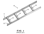
- a vehicle body and frame assembly indicated generally at 10, that is generally conventional in the art.
- the illustrated vehicle frame assembly 10 is a ladder frame assembly including a pair of longitudinally extending side rails, indicated generally at 11 and 12, having a plurality of transverse cross members, indicated generally at 13, extending therebetween.
- the side rails 11 and 12 extend longitudinally throughout the entire length of the assembly 10 and are generally parallel to one another.
- Each of the side rails 11 and 12 in the illustrated embodiment is formed from a single open channel structural member, i.e., a structural member having a non-continuous cross sectional shape (U-shaped or C-shaped channel members, for example).
- one or both of the side rails 11 and 12 may be formed from a plurality of individually formed open channel structural members that are secured together by any conventional means, such as by welding, riveting, bolting, and the like.
- the cross members 13 extend generally perpendicular to the side rails 11 and 12.
- the illustrated cross members 13 are identical in structure, although such is not necessary.
- the cross members 13 are spaced apart from one another along the length of the ladder frame assembly 10 and are secured to the side rails 11 and 12 in a manner at respective joints, the structures of which are described in detail below.
- the cross members 13 through 17 provide lateral and torsional rigidity to the ladder frame assembly 10.
- the side rail 11 is generally C-shaped in cross section, including a generally vertically extending web portion 11a having upper and lower flange portions 11b and 11c extending generally horizontally inwardly therefrom.
- the cross member 13 includes an upper cross member 15 having an end portion composed of a generally vertically extending web portion 15a and a generally horizontally outwardly extending flange portion 15b.
- the cross member 13 further includes a lower cross member 16 having an end portion composed of a generally vertically extending web portion 16a and a generally horizontally outwardly extending flange portion 16b.
- the web portion 16a of the lower cross member 16 abuts the innermost end of the lower flange portion 11c of the side rail 11, while the flange portion 16b of the lower cross member 16 extends across the lower surface of the lower flange portion 11c of the side rail 11.
- the side rail 11 and the cross member 13 are not positively positioned relative to one another, inasmuch as they may be pulled apart from one another (the side rail 11 being moved to the left and the cross member 13 being moved to the right from the position illustrated in Fig. 2).
- the side rail 111 is generally C-shaped in cross section, including a generally vertically extending web portion 111a having upper and lower flange portions 111b and 111c extending generally horizontally inwardly therefrom.
- the upper flange portion 111b is formed having a longitudinally extending, generally U-shaped recess 111b', while the lower flange portion 111c is formed having a longitudinally, extending generally inverted U-shaped recess 111c'.
- the side rail 111 can be formed in this manner using conventional roll forming techniques.
- the cross member 113 includes an upper cross member 115 having an end portion composed of a generally horizontally extending flange portion 115a that terminates in a longitudinally extending, generally U-shaped protrusion 115b.
- the flange portion 115a of the upper cross member 115 extends across the upper surface of the upper flange portion 111b of the side rail 111, while the U-shaped protrusion 115b is received in the U-shaped recess 111b'.
- the cross member 113 further includes a lower cross member 116 having an end portion composed of a generally horizontally extending flange portion 116a that terminates in a longitudinally extending, generally inverted U-shaped protrusion 116b.
- the flange portion 116a of the lower cross member 116 extends across the upper surface of the lower flange portion 111c of the side rail 111, while the inverted U-shaped protrusion 116b is received in the U-shaped recess 111c'.
- the upper and lower cross members 115 and 116 can also be formed in this manner using conventional roll forming techniques.
- a reinforcement member 117 may be provided at the joint between either or both of the upper and lower cross members 115 and 116 with the side rail 111.
- the reinforcement member 117 is generally U-shaped in cross section and is sized to be received within the U-shaped recesses 115b and 116b of the upper and lower cross members 115 and 116, respectively. When so disposed, the reinforcement member 117 provides an additional measure of strength to the joint.
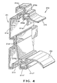
- the side rail 211 is generally C-shaped in cross section, including a generally vertically extending web portion 211a having upper and lower flange portions 211b and 211c extending generally horizontally inwardly therefrom.
- the web portion 211a has a longitudinally extending rib 211a' formed therein to increase the stiffness thereof.
- the upper flange portion 211b is formed having a longitudinally extending, generally inverted U-shaped protrusion 211b' and terminates in a downwardly extending end flange 211b''.
- the lower flange portion 211c is formed having a longitudinally extending, generally U-shaped protrusion 211c' and terminates in an upwardly extending end flange 211c''.
- the side rail 211 can be formed in this manner using conventional roll forming techniques.
- the cross member 213 includes an upper cross member 215 having an end portion composed of a generally vertically extending web portion 215a and a generally horizontally extending flange portion 215b that terminates in a longitudinally extending, generally inverted U-shaped recess 215c.
- the cross member 213 further includes a lower cross member 216 having an end portion composed of a longitudinally extending, generally U-shaped protrusion 216a and a longitudinally extending, generally vertically extending web portion 216b.
- the generally U-shaped protrusion 216a of the lower cross member 216 is received within the generally U-shaped recess 211c' of the side rail 211, and the web portion 216a of the lower cross member abuts the inner surface of the rib 211a' of the side rail 211.
- the upper and lower cross members 215 and 216 can also be formed in this manner using conventional roll forming techniques.
- the side rail 211 and the cross member 213 are positively positioned relative to one another, inasmuch as they cannot be pulled apart from one another.
- the side rail 311 is generally C-shaped in cross section, including a generally vertically extending web portion 311a having upper and lower flange portions 311b and 311c extending generally horizontally inwardly therefrom.
- the web portion 311a has a longitudinally extending rib 311a' formed therein to increase the stiffness thereof.
- the upper flange portion 311b is formed having a longitudinally extending, generally U-shaped recess 311b' and terminates in a longitudinally extending end flange 311b'' that is folded back to abut the rib 311a'.
- the lower flange portion 311c is formed having a longitudinally extending, generally U-shaped protrusion 211c'.
- the side rail 311 can be formed in this manner using conventional roll forming techniques.
- the cross member 313 includes an upper cross member 315 having an end portion composed of a generally vertically extending web portion 315a and a generally horizontally extending flange portion 315b that terminates in a longitudinally extending, generally U-shaped protrusion 315c.
- the cross member 313 further includes a lower cross member 316 having an end portion composed of a longitudinally extending, generally inverted U-shaped recess 316a.
- the generally U-shaped protrusion 311c' of the side rail 311 is received within the generally inverted U-shaped recess 316a of the lower cross member 316.
- the upper and lower cross members 315 and 316 can also be formed in this manner using conventional roll forming techniques.
- the side rail 311 and the cross member 313 are positively positioned relative to one another, inasmuch as they cannot be pulled apart from one another.
Landscapes
- Engineering & Computer Science (AREA)
- Chemical & Material Sciences (AREA)
- Combustion & Propulsion (AREA)
- Transportation (AREA)
- Mechanical Engineering (AREA)
- Body Structure For Vehicles (AREA)
Applications Claiming Priority (2)
| Application Number | Priority Date | Filing Date | Title |
|---|---|---|---|
| US368024 | 1999-08-03 | ||
| US09/368,024 US6189930B1 (en) | 1999-08-03 | 1999-08-03 | Joint between side rail and cross member in a vehicle frame assembly |
Publications (2)
| Publication Number | Publication Date |
|---|---|
| EP1074456A2 true EP1074456A2 (de) | 2001-02-07 |
| EP1074456A3 EP1074456A3 (de) | 2002-02-06 |
Family
ID=23449577
Family Applications (1)
| Application Number | Title | Priority Date | Filing Date |
|---|---|---|---|
| EP00306627A Withdrawn EP1074456A3 (de) | 1999-08-03 | 2000-08-03 | Verbindung zwischen Längsträger und Querträger für Fahrzeugrahmengestelle |
Country Status (4)
| Country | Link |
|---|---|
| US (1) | US6189930B1 (de) |
| EP (1) | EP1074456A3 (de) |
| AR (1) | AR025018A1 (de) |
| BR (1) | BR0003339A (de) |
Cited By (3)
| Publication number | Priority date | Publication date | Assignee | Title |
|---|---|---|---|---|
| DE102007060867A1 (de) * | 2007-12-18 | 2009-06-25 | GM Global Technology Operations, Inc., Detroit | Hinterrahmenstruktur und Verfahren zur Herstellung einer solchen |
| FR3063528A1 (fr) * | 2017-03-03 | 2018-09-07 | Peugeot Citroen Automobiles Sa | Piece avec patte de fixation flexible |
| CN119590519A (zh) * | 2024-12-30 | 2025-03-11 | 上汽通用五菱汽车股份有限公司 | 一种车身侧围及货车 |
Families Citing this family (26)
| Publication number | Priority date | Publication date | Assignee | Title |
|---|---|---|---|---|
| DE19961425B4 (de) * | 1999-12-17 | 2005-10-20 | Zf Lemfoerder Metallwaren Ag | Kraftfahrzeugbauteil |
| US6564892B2 (en) * | 2000-06-13 | 2003-05-20 | International Truck Intellectual Property Company, Llc. | L-bracket modular front engine mounting |
| US6299210B1 (en) * | 2000-08-02 | 2001-10-09 | R. J. Tower Corporation | Multi-piece siderail for medium and heavy trucks |
| CA2361281A1 (en) * | 2000-11-08 | 2002-05-08 | Jeffrey P. Few | Trailer frame |
| US6652020B2 (en) * | 2002-04-09 | 2003-11-25 | Norco Industries, Inc. | Reinforcing bracket for trailer-frame butt joints |
| US6685257B1 (en) | 2002-04-18 | 2004-02-03 | Johnson Controls Technology Company | Extrusion for the siderail of a vehicle to provide head impact countermeasure and support for siderail components |
| US6637809B1 (en) * | 2002-12-12 | 2003-10-28 | International Truck Intellectual Property Company, Llc. | Vehicle with novel frame rails |
| US6681489B1 (en) | 2003-01-31 | 2004-01-27 | Metalsa Roanoke Inc | Method for manufacturing a vehicle frame assembly |
| US7293816B2 (en) * | 2005-04-20 | 2007-11-13 | International Automotive Components Group North America, Inc. | Structural rail system for supporting an overhead console |
| US7896606B2 (en) * | 2006-04-05 | 2011-03-01 | Oshkosh Corporation | Shear plate mounting system |
| US7717498B2 (en) | 2006-04-14 | 2010-05-18 | Metalsa Servicios Sde Rl | Reduced weight components for vehicle frame and method of making same |
| US7857348B2 (en) * | 2006-06-08 | 2010-12-28 | Metalsa Servicios S De Rl | Multi-function cross members for truck frames |
| US7862085B2 (en) * | 2006-11-28 | 2011-01-04 | Gm Global Technologies Operations, Inc. | Three-dimensional vehicle frame |
| DE102007018459B4 (de) * | 2007-04-19 | 2011-11-24 | Audi Ag | Karosseriebauteil für einen Kraftwagen |
| US7789427B2 (en) * | 2008-03-26 | 2010-09-07 | Navistar Canada, Inc. | Chassis frame of a motor vehicle |
| US7926848B2 (en) * | 2008-04-11 | 2011-04-19 | BAE Systems Tactical Vehicle Systems, LP | Light weight beam and truck frame utilizing a light-weight beam |
| JP4625528B2 (ja) * | 2009-02-27 | 2011-02-02 | 株式会社シーデーエスニュースチールホームズインターナショナル | 建物の単位構造部材と該単位構造部材を用いた床構造 |
| DE102011104483A1 (de) * | 2011-06-17 | 2012-12-20 | MAN Truck & Bus Aktiengesellschaft | Rahmenlängsträgeraufbau für Fahrgestellrahmen von Nutzfahrzeugen, insbesondere von Lastkraftwagen und/oder Bussen |
| US8985631B2 (en) | 2011-11-11 | 2015-03-24 | Norco Industries, Inc. | Trailer frame |
| US8491010B2 (en) | 2011-11-11 | 2013-07-23 | Norco Industries, Inc. | Trailer frame |
| US8424913B1 (en) * | 2011-12-21 | 2013-04-23 | International Truck Intellectual Property Company, Llc | Chassis frame of a vehicle |
| US9303405B2 (en) * | 2013-08-13 | 2016-04-05 | Chris A. Nelson | Modular truss system |
| US9623785B2 (en) * | 2015-01-07 | 2017-04-18 | James HYND | Trailer assembly |
| GB2540531B (en) * | 2015-06-01 | 2021-03-24 | Chieftain Trailers Ltd | Chassis leg member |
| KR102506842B1 (ko) * | 2016-11-17 | 2023-03-08 | 현대자동차주식회사 | 차체의 배터리 지지구조 |
| JP6852641B2 (ja) * | 2017-10-16 | 2021-03-31 | トヨタ自動車株式会社 | サイドレールおよびサイドレールの製造方法 |
Family Cites Families (27)
| Publication number | Priority date | Publication date | Assignee | Title |
|---|---|---|---|---|
| GB193088A (en) * | 1921-10-14 | 1923-02-14 | James Jacob Mayrow | Improved construction of joint for frames of hollow metal structures |
| DE976332C (de) | 1940-08-02 | 1963-07-04 | Budd Co | Fahrzeugunterrahmen, insbesondere kombinierter Fahrgestell- und Wagenkasten-Unterrahmen |
| US2356309A (en) | 1941-05-09 | 1944-08-22 | Gustav W Garbe | Construction unit |
| US2508032A (en) | 1945-12-22 | 1950-05-16 | Benjamin H Kennedy | Structural metal member |
| US3234704A (en) | 1962-03-12 | 1966-02-15 | Equipment Mfg Inc | Roll formed sheet metal beam construction |
| US3332197A (en) | 1964-06-30 | 1967-07-25 | James L Hinkle | Interlocked structural assemblies and stiffeners therefor |
| US3611666A (en) | 1970-03-10 | 1971-10-12 | Republic Steel Corp | Sheet metal box beam |
| SE7407353L (sv) * | 1974-06-05 | 1975-12-08 | Scanovator Handel | Sett att framstella balkprofil. |
| US4069638A (en) | 1974-06-05 | 1978-01-24 | Scanovator Ab | Structure of lightweight bars and connector means therefore |
| US4289214A (en) * | 1978-01-28 | 1981-09-15 | Spence William | Multi-purpose vehicle |
| US4226465A (en) * | 1978-11-20 | 1980-10-07 | Mccullough William L | Load supporting frame assembly |
| US4691494A (en) | 1985-06-28 | 1987-09-08 | Gwynne Jacob M | Metal framing system |
| GB2187148B (en) * | 1986-02-10 | 1989-10-25 | British Alcan Aluminium Ltd | Frame construction |
| US4848835A (en) * | 1986-03-14 | 1989-07-18 | American Motors Corporation | Vehicle frame rail assembly and underbody construction |
| US4712942A (en) | 1986-09-22 | 1987-12-15 | Brown Robert K | Joint maker |
| US4760682A (en) | 1987-05-05 | 1988-08-02 | S & K Enterprises Inc. | Tubular rack beam and method of making same |
| US5327989A (en) * | 1991-03-20 | 1994-07-12 | Honda Giken Kogyo Kabushiki Kaisha | Four-wheeled buggy |
| US5205587A (en) * | 1991-04-19 | 1993-04-27 | Paccar Inc. | Modular frame for automotive vehicles |
| US5188418A (en) * | 1992-04-07 | 1993-02-23 | Pullman Industries, Inc. | Truck bed and method of manufacture |
| US5209541A (en) | 1992-04-13 | 1993-05-11 | Ford Motor Company | Space frame joint construction |
| US5332281A (en) * | 1992-04-30 | 1994-07-26 | Ford Motor Company | Space frame construction |
| US5464302A (en) | 1993-08-23 | 1995-11-07 | National Gypsum Company | Extendible interconnected C-studs |
| US5716155A (en) * | 1993-09-16 | 1998-02-10 | Honda Giken Kogyo Kabushiki Kaisha | T-shaped connection frame |
| DE4422498C1 (de) * | 1994-06-28 | 1995-10-19 | Porsche Ag | Aufbaustruktur eines Personenkraftwagens |
| US5480189A (en) * | 1994-08-12 | 1996-01-02 | Ford Motor Company | Automotive vehicle frame |
| US6092862A (en) * | 1996-05-14 | 2000-07-25 | Isuzu Motors Limited | Floor structure for truck's load-carrying platform |
| US5938272A (en) * | 1997-01-10 | 1999-08-17 | Pullman Industries, Inc. | Vehicle bed |
-
1999
- 1999-08-03 US US09/368,024 patent/US6189930B1/en not_active Expired - Fee Related
-
2000
- 2000-08-02 BR BR0003339-1A patent/BR0003339A/pt not_active Application Discontinuation
- 2000-08-02 AR ARP000103988A patent/AR025018A1/es unknown
- 2000-08-03 EP EP00306627A patent/EP1074456A3/de not_active Withdrawn
Non-Patent Citations (1)
| Title |
|---|
| None |
Cited By (3)
| Publication number | Priority date | Publication date | Assignee | Title |
|---|---|---|---|---|
| DE102007060867A1 (de) * | 2007-12-18 | 2009-06-25 | GM Global Technology Operations, Inc., Detroit | Hinterrahmenstruktur und Verfahren zur Herstellung einer solchen |
| FR3063528A1 (fr) * | 2017-03-03 | 2018-09-07 | Peugeot Citroen Automobiles Sa | Piece avec patte de fixation flexible |
| CN119590519A (zh) * | 2024-12-30 | 2025-03-11 | 上汽通用五菱汽车股份有限公司 | 一种车身侧围及货车 |
Also Published As
| Publication number | Publication date |
|---|---|
| AR025018A1 (es) | 2002-11-06 |
| BR0003339A (pt) | 2001-03-13 |
| US6189930B1 (en) | 2001-02-20 |
| EP1074456A3 (de) | 2002-02-06 |
Similar Documents
| Publication | Publication Date | Title |
|---|---|---|
| US6189930B1 (en) | Joint between side rail and cross member in a vehicle frame assembly | |
| US6398260B1 (en) | Side rail for a vehicle frame assembly | |
| US6099194A (en) | Splice joint for connecting adjacent side rail sections in a vehicle body and frame assembly | |
| US6733040B1 (en) | Closed channel structural member having internal reinforcement for vehicle body and frame assembly | |
| US7144040B2 (en) | Bi-metallic structural component for vehicle frame assembly | |
| US6434907B1 (en) | Closed channel structural member having internal reinforcement for vehicle body and frame assembly | |
| US5634663A (en) | Vehicle frame joint | |
| EP0009975B1 (de) | Lasttragende Bauelemente und Kraftfahrzeugrahmen, die solche Elemente enthalten | |
| EP0722401B1 (de) | Endabschnitt eines rahmenteils für ein fahrzeug | |
| US6412818B1 (en) | Vehicle body and frame assembly and method of manufacturing same | |
| FI84246C (fi) | Fordonsflak. | |
| EP1241078A1 (de) | Fabrikationsverfahren für eine Kraftfahrzeug-Rahmenstruktur und -Karosserie mit aufprallabsorbierender Struktur | |
| ITRM970318A1 (it) | Struttura di connessione e supporto per complesso di telaio di veicolo | |
| KR100253881B1 (ko) | 서스펜션 프레임 브래킷 | |
| US7389586B2 (en) | Method for producing a Y-shaped node structure for the supporting frame of a motor vehicle | |
| US7032928B2 (en) | Vehicle frame | |
| US4401341A (en) | Panel reinforcement structure construction | |
| US20040159995A1 (en) | Sandwich design of four bag suspension for bus and coach rear drive axles | |
| RU2588629C2 (ru) | Корпус промышленного транспортного средства, у которого основание сиденья объединено с полом, и способ изготовления корпуса промышленного транспортного средства | |
| US7334308B1 (en) | Method of securing a body mount support bracket on a vehicle body and frame assembly | |
| CN116176700B (zh) | 车架和客车 | |
| JPH077261Y2 (ja) | トラックの車台フレーム | |
| CN222179627U (zh) | 车架和车辆 | |
| JP3196442B2 (ja) | シートブラケット取付部の車体フロアへの結合構造 | |
| CA1141797A (en) | Motor vehicle frame structure |
Legal Events
| Date | Code | Title | Description |
|---|---|---|---|
| PUAI | Public reference made under article 153(3) epc to a published international application that has entered the european phase |
Free format text: ORIGINAL CODE: 0009012 |
|
| AK | Designated contracting states |
Kind code of ref document: A2 Designated state(s): AT BE CH CY DE DK ES FI FR GB GR IE IT LI LU MC NL PT SE Kind code of ref document: A2 Designated state(s): DE GB IT |
|
| AX | Request for extension of the european patent |
Free format text: AL;LT;LV;MK;RO;SI |
|
| PUAL | Search report despatched |
Free format text: ORIGINAL CODE: 0009013 |
|
| AK | Designated contracting states |
Kind code of ref document: A3 Designated state(s): AT BE CH CY DE DK ES FI FR GB GR IE IT LI LU MC NL PT SE |
|
| AX | Request for extension of the european patent |
Free format text: AL;LT;LV;MK;RO;SI |
|
| RIC1 | Information provided on ipc code assigned before grant |
Free format text: 7B 62D 21/12 A, 7B 62D 65/00 B, 7B 62D 21/02 B |
|
| 17P | Request for examination filed |
Effective date: 20020729 |
|
| AKX | Designation fees paid |
Free format text: DE GB IT |
|
| 17Q | First examination report despatched |
Effective date: 20030715 |
|
| STAA | Information on the status of an ep patent application or granted ep patent |
Free format text: STATUS: THE APPLICATION IS DEEMED TO BE WITHDRAWN |
|
| 18D | Application deemed to be withdrawn |
Effective date: 20031126 |