EP1075047A2 - Connecteur électrique pour câble plat - Google Patents
Connecteur électrique pour câble plat Download PDFInfo
- Publication number
- EP1075047A2 EP1075047A2 EP00306539A EP00306539A EP1075047A2 EP 1075047 A2 EP1075047 A2 EP 1075047A2 EP 00306539 A EP00306539 A EP 00306539A EP 00306539 A EP00306539 A EP 00306539A EP 1075047 A2 EP1075047 A2 EP 1075047A2
- Authority
- EP
- European Patent Office
- Prior art keywords
- housing
- flat cable
- electrical connector
- press
- connection arms
- Prior art date
- Legal status (The legal status is an assumption and is not a legal conclusion. Google has not performed a legal analysis and makes no representation as to the accuracy of the status listed.)
- Granted
Links
Images



Classifications
-
- H—ELECTRICITY
- H01—ELECTRIC ELEMENTS
- H01R—ELECTRICALLY-CONDUCTIVE CONNECTIONS; STRUCTURAL ASSOCIATIONS OF A PLURALITY OF MUTUALLY-INSULATED ELECTRICAL CONNECTING ELEMENTS; COUPLING DEVICES; CURRENT COLLECTORS
- H01R13/00—Details of coupling devices of the kinds covered by groups H01R12/70 or H01R24/00 - H01R33/00
- H01R13/40—Securing contact members in or to a base or case; Insulating of contact members
- H01R13/42—Securing in a demountable manner
- H01R13/436—Securing a plurality of contact members by one locking piece or operation
-
- H—ELECTRICITY
- H01—ELECTRIC ELEMENTS
- H01R—ELECTRICALLY-CONDUCTIVE CONNECTIONS; STRUCTURAL ASSOCIATIONS OF A PLURALITY OF MUTUALLY-INSULATED ELECTRICAL CONNECTING ELEMENTS; COUPLING DEVICES; CURRENT COLLECTORS
- H01R12/00—Structural associations of a plurality of mutually-insulated electrical connecting elements, specially adapted for printed circuits, e.g. printed circuit boards [PCB], flat or ribbon cables, or like generally planar structures, e.g. terminal strips, terminal blocks; Coupling devices specially adapted for printed circuits, flat or ribbon cables, or like generally planar structures; Terminals specially adapted for contact with, or insertion into, printed circuits, flat or ribbon cables, or like generally planar structures
- H01R12/70—Coupling devices
- H01R12/77—Coupling devices for flexible printed circuits, flat or ribbon cables or like structures
- H01R12/771—Details
- H01R12/774—Retainers
-
- H—ELECTRICITY
- H01—ELECTRIC ELEMENTS
- H01R—ELECTRICALLY-CONDUCTIVE CONNECTIONS; STRUCTURAL ASSOCIATIONS OF A PLURALITY OF MUTUALLY-INSULATED ELECTRICAL CONNECTING ELEMENTS; COUPLING DEVICES; CURRENT COLLECTORS
- H01R12/00—Structural associations of a plurality of mutually-insulated electrical connecting elements, specially adapted for printed circuits, e.g. printed circuit boards [PCB], flat or ribbon cables, or like generally planar structures, e.g. terminal strips, terminal blocks; Coupling devices specially adapted for printed circuits, flat or ribbon cables, or like generally planar structures; Terminals specially adapted for contact with, or insertion into, printed circuits, flat or ribbon cables, or like generally planar structures
- H01R12/70—Coupling devices
- H01R12/77—Coupling devices for flexible printed circuits, flat or ribbon cables or like structures
- H01R12/79—Coupling devices for flexible printed circuits, flat or ribbon cables or like structures connecting to rigid printed circuits or like structures
-
- H—ELECTRICITY
- H01—ELECTRIC ELEMENTS
- H01R—ELECTRICALLY-CONDUCTIVE CONNECTIONS; STRUCTURAL ASSOCIATIONS OF A PLURALITY OF MUTUALLY-INSULATED ELECTRICAL CONNECTING ELEMENTS; COUPLING DEVICES; CURRENT COLLECTORS
- H01R12/00—Structural associations of a plurality of mutually-insulated electrical connecting elements, specially adapted for printed circuits, e.g. printed circuit boards [PCB], flat or ribbon cables, or like generally planar structures, e.g. terminal strips, terminal blocks; Coupling devices specially adapted for printed circuits, flat or ribbon cables, or like generally planar structures; Terminals specially adapted for contact with, or insertion into, printed circuits, flat or ribbon cables, or like generally planar structures
- H01R12/70—Coupling devices
- H01R12/82—Coupling devices connected with low or zero insertion force
- H01R12/85—Coupling devices connected with low or zero insertion force contact pressure producing means, contacts activated after insertion of printed circuits or like structures
- H01R12/89—Coupling devices connected with low or zero insertion force contact pressure producing means, contacts activated after insertion of printed circuits or like structures acting manually by moving connector housing parts linearly, e.g. slider
-
- H—ELECTRICITY
- H01—ELECTRIC ELEMENTS
- H01R—ELECTRICALLY-CONDUCTIVE CONNECTIONS; STRUCTURAL ASSOCIATIONS OF A PLURALITY OF MUTUALLY-INSULATED ELECTRICAL CONNECTING ELEMENTS; COUPLING DEVICES; CURRENT COLLECTORS
- H01R12/00—Structural associations of a plurality of mutually-insulated electrical connecting elements, specially adapted for printed circuits, e.g. printed circuit boards [PCB], flat or ribbon cables, or like generally planar structures, e.g. terminal strips, terminal blocks; Coupling devices specially adapted for printed circuits, flat or ribbon cables, or like generally planar structures; Terminals specially adapted for contact with, or insertion into, printed circuits, flat or ribbon cables, or like generally planar structures
- H01R12/70—Coupling devices
- H01R12/71—Coupling devices for rigid printing circuits or like structures
- H01R12/712—Coupling devices for rigid printing circuits or like structures co-operating with the surface of the printed circuit or with a coupling device exclusively provided on the surface of the printed circuit
- H01R12/716—Coupling device provided on the PCB
Definitions
- the present invention relates to an electrical connector for flat cable for connecting a flexible board such as an FPC (Flexible Printed Circuit) board or a flat cablesuch as an FFC (Flexible Flat Cable) to a circuit board.
- a flexible board such as an FPC (Flexible Printed Circuit) board or a flat cable such as an FFC (Flexible Flat Cable) to a circuit board.
- FPC Flexible Printed Circuit
- FFC Flexible Flat Cable
- slide-type retainer for use in connectors of this type
- FPC board flexible printed circuit board
- the insertable projection is inserted in an insertion space of a synthetic-resin housing retaining a group of contacts, thereby pressing the FPC board into contact with the contact group.
- the pair of connection arms serve to interconnect the housing and the retainer, extending from transversely opposite ends of the main body along lateral side surfaces of the housing in a manner to sandwich the insertable projection therebetween.
- connection arms of the retainer are slidably received by guide grooves formed at lateral sides of the housing. With the connection arms drawn out to their limit (moved to forward position), engaged sections formed at the connection arms are engaged with anti-deviation stoppers provided in the guide grooves, whereby the retainer is prevented from being drawn any further.
- connection arms is prevented by way of the engagement between the synthetic resin members, which engagement tends to become loose.
- synthetic resin members fail to positively prevent the deviation of the arms.
- connection arms In order to assemble the connection arms in the housing, the arms must be resiliently deformed to allow their engaged sections to slide over the anti-deviation stoppers of the housing. Unfortunately, a great amount of deformation of the connection arms may result in plastic deformation thereof.
- an electrical connector for flat cable for removably connecting a flat cable at its end comprises a housing defining an insertion space for insertion of the flat cable in a predetermined direction, a retainer connected to the housing such as to be allowed to slide in the predetermined inserting direction, and a reinforcement member made of metal and fixed to the housing, wherein the reinforcement member includes inhibition means for inhibiting removal of the retainer from the housing.
- This arrangement utilizes the metallic member for preventing the deviation of the retainer, thus accomplishing reliable prevention of the deviation of the retainer.
- the reinforcement member is soldered to a circuit board so as to be fixed thereto. This results in positive prevention of the deviation of the retainer.
- the reinforcement member soldered to the circuit board is normally disposed at the connector mounted on the circuit board surface. Therefore, the number of components is not increased.
- the retainer includes an insertable projection slidably inserted in the insertion space, and a pair of connection arms slidably received by a pair of slide grooves of the housing for connection with the housing, whereas the insertable projection includes a pressing portion for pressing an end of the flat cable in the insertion space into contact with a group of contacts.
- This arrangement positively prevents the connection arms from deviating from the slide grooves.
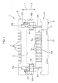
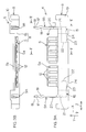
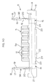
- a connector 1 includes a housing 4 retaining a plurality of contacts 3 transversely arranged in its insertion space 2 opening in a forward direction X, and a slider 6 having an insertable projection 5 to be inserted in or removed from the insertion space 2 of the housing 4.
- the insertable projection 5 is inserted into the insertion space 2 in a predetermined insertion direction (equivalent to a rearward direction Y) together with an FPC 7 as the flat cable (see Figs.7 and 9B) .
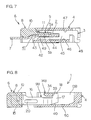
- the insertable projection presses the FPC 7 into contact with the plural contacts 3 by means of its lower surface 5b, shown in Figs.3B, 5 and 7, serving as a pressing portion.
- the slider 6 includes a main body 8 formed of a synthetic resin, and a pair of connection arms 9A, 9B, made of metal, which are mirror images of each other.
- the connection arms 9A, 9B are independent from each other and partially embedded in the main body 8 by insert molding.
- the main body 8 includes an elongate body section 10 extending transversely, and the insertable projection 5 extending from the body section 10.
- the insertable projection 5 is formed with receiving grooves 12 in its upper surface 5a, which individually correspond to fixing pieces 11 (Fig.7) of fork-shaped portions of the contacts 3 (see Figs.1, 3A and 3B).
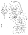
- the housing 4 includes a pair of symmetrical slide grooves 13A, 13B opening in the forward direction X and an upward direction W (Fig.4), the grooves being located in laterally opposite places with respect to the insertion space 2.
- the connection arms 9A, 9B of the slider 6 are adapted to slide in the forward direction X and the rearward direction Y (the directions to remove and insert the insertable projection 5) as received by the corresponding slide grooves 13A, 13B.
- the connection arms are also prevented from deviating from the slide grooves 13A, 13B by corresponding reinforcement tabs 14A, 14B made of metal.
- the reinforcement tabs 14A, 14B are symmetrically shaped. After the connection arms 9A, 9B are inserted in the slide grooves 13A, 13B, the reinforcement tabs are press-inserted from above to be fixed to given places of the housing 4 in a manner to span the respective slide grooves 13A, 13B.
- connection arms 9A, 9B each include a lock section 19.
- the lock sections 19 come into engagement with corresponding engageable extensions 25 disposed in the slide grooves 13A, 13B, thereby locking the slider 6 to the housing 4.
- the contact 3 includes a resilient piece 44 inserted in a receiving groove 43 formed in a top surface of a lower plate 42 of the housing 4, and the fixing piece 11 disposed above the resilient piece 44 to form the fork shape jointly with the resilient piece 44.
- the fixing piece 11 and the resilient piece 44 have their rear end portions interconnected by a main body 45.
- the main body 45 includes a locking projection 46 wedgingly engaging the lower plate 42.
- the main body 45 is press-inserted, from the rear, into a fixing hole 47 of the housing 4 to be fixed therein.
- the main body 45 also has a substantially L-shaped lead portion 48 extending from an upper part of a rear end thereof.
- the lead portion 48 is soldered to a board surface on which the connector 1 is mounted.
- a chevron-shaped projection 49 ensures contact pressure by pressing against the inserted FPC 7.
- an unhatched area represents the section of the contact 3.
- connection arms 9A, 9B of the slider 6 are each formed of a sheet metal into shape, including a buried portion 15 buried in the body section 10 of the main body 8, and a projecting portion 16 extended outwardly of the body section 10 in parallel relation with the insertable projection 5.
- the projecting portion 16 extends in the sliding direction Y.
- the buried portion 15 includes a first section 21 coplanar with the projecting portion 16 and extending in the sliding direction X, and a second section 22 extending in a direction Z crossed by the sliding direction X as bent square to the first section 21.
- a substantially L-shaped piece of flat sheet metal in development is worked in such a manner that one part thereof (defining the second section 22) is bent square to the other part (defining the projecting portion 16 and the first section 21 of the buried portion 15). Since the buried portion 15 includes the bent section (the second section) extending in the direction Z crossed by the sliding direction X, the connection arm 9A, 9B is positively prevented from deviating from the body section 10.
- the projecting portion 16 extends parallel to a side surface 5b of the insertable projection 5 (or parallel to a side surface 4a of the housing 4).
- a distal end 17 of the projecting portion 16 defines a hook portion 18 projecting upwardly in a hook-like fashion.
- the distal end 17 of the projecting portion 16 is tapered at its lower side which thus defines a slope 40 inclined upwardly toward the end.
- connection arm 9B(9A) can be inclined by bringing the slope 40 into intimate contact with a lower plate 50 of the slide groove 13B, as shown in Fig.9A. Therefore, a relatively large entrance to an introduction space 41 for the FPC 7 may be defined below the insertable projection 5 in the insertion space 2, as shown in Fig.9B. This facilitates the insertion of the FPC 7.
- connection arms 9A, 9B are formed with the lock sections 19 near the respective distal ends 17 thereof, the lock sections being comprised of a recess and disposed in face-to-face relation.
- the lock sections 19 With the insertable projection 5 positioned to press the FPC 7 into contact with the plural contacts 3, the lock sections 19 are in engagement with the engageable extensions 25 in the slide grooves 13A, 13B of the housing 4 thereby locking the slider 6 to the housing 4.
- connection arms 9A, 9B are resiliently distended so as to allow the distal ends 17 of the projecting portions 16 to slide over the corresponding engageable extensions 25, thereby bringing their lock sections 19 into engagement with the engageable extensions 25, as shown in Fig.2.
- Indicated at 20 is a bead portion comprised of a hollow projected rib for reinforcement of the projecting portion 16.
- the first section 21 of each buried portion 15 is of a vertical plate continuous to the projecting portion 16, whereas the second section 22 is of a horizontal plate bent into square along a line corresponding to an upper edge of the first section 21 and extending toward the counterpart buried portion 15.
- the second section 22 includes a projection 23, which is exposed outside via a recess 24 formed in the body section 10.
- the projection 23 is used for retaining the connection arm 9A, 9B in place during molding so as to prevent the connection arm from being displaced in molding dies. That is, the connection arm 9A, 9B may be positioned with high precision because the connection arm 9A, 9B is retained at both a part defining the projecting portion 16 and a part defining the projection 23 during the insert molding thereby ensuring the prevention of displacement thereof.
- the slide groove 13B extends parallel with the side surface 4a of the housing 4.
- the slide groove opens in the forward direction X and the upward direction W for receiving the corresponding connection arm 9B from the front.
- the one 26 away from the side surface 4a is vertically formed with a first press-fit groove 28 at a place closer to its front end, the groove 28 communicating with the slide groove 13B and press-fittedly receiving the reinforcement tab.
- the side wall 26 is further formed with the engageable extension 25 at a place closer to its rear end.
- the first press-fit groove 28 opens upward.
- the engageable extension 25 is of a chevron shape in section and vertically extended.
- the side wall 27 closer to the side surface 4a is formed with a relief groove 29 at its upper part, corresponding to the position of the first press-fit groove 28.
- the side wall 27 is further formed with a second press-fit groove 30 comprised of a through groove for press-fittedly receiving the reinforcement tab, the groove extending along an overall vertical length of an outer side of the side wall 27.
- a large part of the press-fit groove 30 opens to the side surface 4a of the housing 4 so that only a rear part 31 thereof is defined by opposite side walls.
- the reinforcement tab 14B is formed of a sheet metal into a ladle-like shape in front elevation.
- the reinforcement tab 14B includes first and second press-fitted sections 32, 33 as fixed portions to be press-fitted in the first and second press-fit grooves 28, 30, and an interconnection section 34 interconnecting respective upper ends of the first and second press-fitted sections 32, 33.
- the press-fitted section 33 includes an extension 35 extending rearwardly.
- the first press-fitted section 32 is formed with a press-fit projection 36 at its rear end surface, whereas a press-fit projection 37 is formed at a rear end surface of the extension 35 of the second press-fitted section 33.
- a leg 38 extends horizontally from a lower end of the second press-fitted section 33, being bent square thereto.
- the leg 38 is soldered to a conductive area of a printed circuit board 51.
- the leg is shaped like comb teeth for increased solderability.
- a rear edge of the interconnection section 34 defines an anti-deviation engagement section 39 which engages the hook portion 18 of the connection arm 9B for preventing the connection arm 9B from being displaced forwardly out of the slide groove 13B.
- the connection arm 9B is adapted to slide with a lower edge of the projecting portion 16 thereof guided by the lower plate 50 defining the bottom of the slide groove 13B, as shown in Fig.8.
- connection arm 9B After the connection arm 9B is inserted, from the front, into the slide groove 13B, the reinforcement tab 14B is mounted to the housing 4 in such a manner that the first and second press-fitted sections 32, 33 are press-fitted in the first and second press-fit grooves 28, 30 of the housing 4, respectively.
- the reinforcement tab serves as the anti-deviation section for the connection arm 9B.
- the embodiment of the invention is designed to prevent the deviation of the connection arms 9A, 9B by way of engagement between the hook portions 18 of the connection arms 9A, 9B and the anti-deviation engagement sections 39 of the reinforcement tabs 14A, 14B. Since the metallic members define the anti-deviation sections for the connection arms 9A, 9B, the deviation of the connection arms is positively prevented. In addition, the metallic reinforcement tabs 14A, 14B normally included in the connector mounted on the board surface are used as the metallic members defining the anti-deviation sections so that the number of components is not increased.
- the reinforcement tab 14A, 14B is rigidly secured to the press-fit grooves 28, 30 of the housing 4 by press-fitting the pair of press-fitted sections 32, 33 thereof on the opposite sides of the interconnection section 34 including the anti-deviation engagement section 39, thus accomplishing a more reliable anti-deviation effect. Since the anti-deviation effect is accomplished through the engagement between the metallic members, the connection arms 9A, 9B are more positively prevented from deviating.
- connection arms 9A, 9B are rigidly connected to the main body 8 because they are inserted in a synthetic resin being molded to form the main body 8. Besides, the connection arms 9A, 9B, being reduced in thickness and size, permit the so-called inner-lock layout such as of the invention to be embodied in the connector 1 which need not be enlarged. This contributes to the downsizing and thin design of the connector 1.
- the slide grooves 13A, 13B opening forwardly and upwardly of the housing 4 and the press-fit grooves 28, 30 opening upwardly of the housing 4 allow for assembly steps of slidingly inserting the connection arms 9A, 9B of the slider 6 into the slide grooves 13A, 13B of the housing 4 from the front and then press-fitting the reinforcement tabs 14A, 14B into the press-fit grooves 28, 30 of the housing 4 from above, resulting in improved ease of assembly of the connector 1.
- the arrangement of the embodiment does not involve excessive deformation of the connection arms during assembly because the connection arms need not be slid over the anti-deviation stoppers.
- connection arms 9A, 9B may be interconnected at the second sections 22 of their buried portions 15 so that the connection arms 9A, 9B may be formed of one piece.
- connection arms may be formed of a synthetic resin into one piece combined with the main body of the slider.
- the invention is also applicable to a layout of a non-inner lock type wherein the slide grooves open laterally of the housing.
- the connector is a so-called back-side contact type wherein a back side of the FPC 7 is pressed into contact with the contacts disposed thereunder.
- the invention is not limited to the above and the connector may be of a so-called top-side contact type wherein a top side of the FPC 7 is pressed into contact with the contacts disposed thereabove.
- the press-fit grooves open upwardly of the housing for press-fitting the reinforcement tabs from above the housing
- the invention is not limited to this arrangement.
- the press-fit grooves may open downwardly of the housing for press-fitting the reinforcement tabs from beneath the housing and fixing in place.
- the slide grooves also open downwardly.
- the invention is also applicable to a so-called vertical-type connector wherein the housing 4 is laid out on the circuit board in such a manner that the insertion space 2 opens upward for insertion or removal of the slider 6 from above.
- reinforcement tab 14A, 14B may omit either one of the press-fitted sections 32, 33 thereof.
- Various other modifications may be contemplated within the scope of the invention.
Landscapes
- Coupling Device And Connection With Printed Circuit (AREA)
Applications Claiming Priority (2)
| Application Number | Priority Date | Filing Date | Title |
|---|---|---|---|
| JP22028499A JP4226737B2 (ja) | 1999-08-03 | 1999-08-03 | フラットケーブル用コネクタ及びその製造方法 |
| JP22028499 | 1999-08-03 |
Publications (3)
| Publication Number | Publication Date |
|---|---|
| EP1075047A2 true EP1075047A2 (fr) | 2001-02-07 |
| EP1075047A3 EP1075047A3 (fr) | 2003-05-14 |
| EP1075047B1 EP1075047B1 (fr) | 2006-02-01 |
Family
ID=16748771
Family Applications (1)
| Application Number | Title | Priority Date | Filing Date |
|---|---|---|---|
| EP00306539A Expired - Lifetime EP1075047B1 (fr) | 1999-08-03 | 2000-08-01 | Connecteur électrique pour câble plat |
Country Status (7)
| Country | Link |
|---|---|
| US (1) | US6315603B1 (fr) |
| EP (1) | EP1075047B1 (fr) |
| JP (1) | JP4226737B2 (fr) |
| KR (1) | KR100716512B1 (fr) |
| CN (1) | CN1142617C (fr) |
| DE (1) | DE60025795T2 (fr) |
| TW (1) | TW531097U (fr) |
Cited By (1)
| Publication number | Priority date | Publication date | Assignee | Title |
|---|---|---|---|---|
| EP1737081A4 (fr) * | 2004-03-31 | 2008-04-02 | Framatome Connectors Int | Connecteur se raccordant verticalement |
Families Citing this family (13)
| Publication number | Priority date | Publication date | Assignee | Title |
|---|---|---|---|---|
| US7040910B2 (en) * | 2001-08-02 | 2006-05-09 | Hosiden Corporation | Plug type connector |
| JP2003123881A (ja) * | 2001-10-15 | 2003-04-25 | Molex Inc | 平型柔軟ケーブル用電気コネクタ |
| JP2004273270A (ja) * | 2003-03-07 | 2004-09-30 | Jst Mfg Co Ltd | 電気コネクタ |
| TWM249292U (en) * | 2003-10-31 | 2004-11-01 | P Two Ind Inc | Soft circuit board connector capable of preventing detaching of movable cap |
| CN2757357Y (zh) * | 2004-11-18 | 2006-02-08 | 富士康(昆山)电脑接插件有限公司 | 电连接器 |
| CN2800515Y (zh) * | 2005-04-08 | 2006-07-26 | 富士康(昆山)电脑接插件有限公司 | 电连接器 |
| JP5631102B2 (ja) * | 2010-08-10 | 2014-11-26 | 矢崎総業株式会社 | 平板状ケーブル用コネクタ |
| JP5600523B2 (ja) * | 2010-08-27 | 2014-10-01 | 矢崎総業株式会社 | コネクタ構造 |
| JP6084107B2 (ja) * | 2013-04-26 | 2017-02-22 | 矢崎総業株式会社 | コネクタ |
| JP6857073B2 (ja) * | 2017-04-07 | 2021-04-14 | モレックス エルエルシー | コネクタ及びコネクタ組立体 |
| JP6355181B1 (ja) * | 2017-08-29 | 2018-07-11 | マフレン株式会社 | ベルトクリーナ |
| DE102018000207A1 (de) * | 2018-01-12 | 2019-07-18 | Kostal Kontakt Systeme Gmbh | Steckverbinderanordnung |
| US11837808B2 (en) * | 2018-12-28 | 2023-12-05 | Autonetworks Technologies, Ltd. | Board connector and device |
Family Cites Families (9)
| Publication number | Priority date | Publication date | Assignee | Title |
|---|---|---|---|---|
| US3084302A (en) * | 1960-12-01 | 1963-04-02 | Hughes Aircraft Co | Electrical ribbon cable connector |
| US3149897A (en) * | 1961-08-29 | 1964-09-22 | Hans G Martineck | Printed cable connector |
| JPH0682783U (ja) | 1993-04-27 | 1994-11-25 | 日本バーンデイ株式会社 | フラットケーブル用コネクタ |
| US5354214A (en) * | 1993-07-23 | 1994-10-11 | Molex Incorporated | Printed circuit board electrical connector with mounting latch clip |
| JPH07106028A (ja) | 1993-10-12 | 1995-04-21 | Kiyousera Elco Kk | Fpcコネクタ装置 |
| US5639260A (en) * | 1995-09-26 | 1997-06-17 | Hon Hai Precision Ind. Co., Ltd. | Electrical connector for use with flexible printed circuit |
| US5882223A (en) * | 1996-02-21 | 1999-03-16 | Japan Aviation Delectronics Industry, Limited | Connector which is adapted to connect a flat connection object having a signal pattern and a shield pattern opposite to each other |
| JPH09283236A (ja) | 1996-04-09 | 1997-10-31 | Sumitomo Wiring Syst Ltd | フレキシブルプリント基板用コネクタ |
| JP3269029B2 (ja) * | 1998-06-16 | 2002-03-25 | エスエムケイ株式会社 | コネクタのロック構造 |
-
1999
- 1999-08-03 JP JP22028499A patent/JP4226737B2/ja not_active Expired - Fee Related
-
2000
- 2000-08-01 DE DE60025795T patent/DE60025795T2/de not_active Expired - Fee Related
- 2000-08-01 TW TW091203899U patent/TW531097U/zh not_active IP Right Cessation
- 2000-08-01 US US09/630,603 patent/US6315603B1/en not_active Expired - Lifetime
- 2000-08-01 EP EP00306539A patent/EP1075047B1/fr not_active Expired - Lifetime
- 2000-08-02 CN CNB001209663A patent/CN1142617C/zh not_active Expired - Fee Related
- 2000-08-03 KR KR1020000044996A patent/KR100716512B1/ko not_active Expired - Fee Related
Cited By (1)
| Publication number | Priority date | Publication date | Assignee | Title |
|---|---|---|---|---|
| EP1737081A4 (fr) * | 2004-03-31 | 2008-04-02 | Framatome Connectors Int | Connecteur se raccordant verticalement |
Also Published As
| Publication number | Publication date |
|---|---|
| CN1291806A (zh) | 2001-04-18 |
| DE60025795T2 (de) | 2006-10-12 |
| EP1075047B1 (fr) | 2006-02-01 |
| KR100716512B1 (ko) | 2007-05-09 |
| KR20010021200A (ko) | 2001-03-15 |
| JP4226737B2 (ja) | 2009-02-18 |
| CN1142617C (zh) | 2004-03-17 |
| US6315603B1 (en) | 2001-11-13 |
| EP1075047A3 (fr) | 2003-05-14 |
| JP2001052786A (ja) | 2001-02-23 |
| DE60025795D1 (de) | 2006-04-13 |
| TW531097U (en) | 2003-05-01 |
Similar Documents
| Publication | Publication Date | Title |
|---|---|---|
| US6116939A (en) | Connector lock mechanism | |
| EP1075047B1 (fr) | Connecteur électrique pour câble plat | |
| EP1075046B1 (fr) | Dispositif de retenue pour connecteur électrique et connecteur électrique | |
| US7048573B2 (en) | Plug-type connector and electric connector comprising the same | |
| US5797774A (en) | Contact | |
| TW471198B (en) | Connector for flexible printed board | |
| EP1643599B1 (fr) | Organe de contact et connecteur avec un tel organe de contact | |
| EP1004973A2 (fr) | Connecteur pour carte à puce | |
| CA1044777A (fr) | Borne femelle a insertion pour circuit imprime | |
| JPH02244574A (ja) | コネクタ | |
| EP0407864A2 (fr) | Connecteur de bordure pour plaque de circuit imprimé | |
| EP1198031A2 (fr) | Connecteur avec structure de renforcement pour fixer le boítier de connecteur à un panneau à circuit | |
| US5860838A (en) | Tangle-preventive mechanism in three contact pieces type contact | |
| US6334790B2 (en) | Electrical connection and housing having a lance in a terminal accommodation chamber | |
| US6814618B2 (en) | Connector with resilient coupling pieces coupling locks in adjacent cavities | |
| US4423288A (en) | Modular telephone jack | |
| US6565389B1 (en) | Connector of a thin type | |
| US4209220A (en) | Wipe-in terminal for printed circuits | |
| JP2002184493A (ja) | コネクタ | |
| JP2001052787A (ja) | 接続アーム付きスライダ | |
| US20040259417A1 (en) | Connector and method of molding a connector | |
| EP0821450A1 (fr) | Connecteur électrique monté sur plaquette de circuits | |
| US20060141839A1 (en) | Electrical card connector | |
| JPS6239586Y2 (fr) | ||
| JP3299643B2 (ja) | コネクタの接続端子係止構造 |
Legal Events
| Date | Code | Title | Description |
|---|---|---|---|
| PUAI | Public reference made under article 153(3) epc to a published international application that has entered the european phase |
Free format text: ORIGINAL CODE: 0009012 |
|
| AK | Designated contracting states |
Kind code of ref document: A2 Designated state(s): AT BE CH CY DE DK ES FI FR GB GR IE IT LI LU MC NL PT SE |
|
| AX | Request for extension of the european patent |
Free format text: AL;LT;LV;MK;RO;SI |
|
| PUAL | Search report despatched |
Free format text: ORIGINAL CODE: 0009013 |
|
| AK | Designated contracting states |
Designated state(s): AT BE CH CY DE DK ES FI FR GB GR IE IT LI LU MC NL PT SE |
|
| AX | Request for extension of the european patent |
Extension state: AL LT LV MK RO SI |
|
| 17P | Request for examination filed |
Effective date: 20031030 |
|
| 17Q | First examination report despatched |
Effective date: 20031205 |
|
| AKX | Designation fees paid |
Designated state(s): DE FR GB IT |
|
| GRAP | Despatch of communication of intention to grant a patent |
Free format text: ORIGINAL CODE: EPIDOSNIGR1 |
|
| RBV | Designated contracting states (corrected) |
Designated state(s): DE FR GB IT |
|
| RBV | Designated contracting states (corrected) |
Designated state(s): DE FR GB IT |
|
| GRAS | Grant fee paid |
Free format text: ORIGINAL CODE: EPIDOSNIGR3 |
|
| GRAA | (expected) grant |
Free format text: ORIGINAL CODE: 0009210 |
|
| AK | Designated contracting states |
Kind code of ref document: B1 Designated state(s): DE FR GB IT |
|
| REG | Reference to a national code |
Ref country code: GB Ref legal event code: FG4D |
|
| REF | Corresponds to: |
Ref document number: 60025795 Country of ref document: DE Date of ref document: 20060413 Kind code of ref document: P |
|
| ET | Fr: translation filed | ||
| PLBE | No opposition filed within time limit |
Free format text: ORIGINAL CODE: 0009261 |
|
| STAA | Information on the status of an ep patent application or granted ep patent |
Free format text: STATUS: NO OPPOSITION FILED WITHIN TIME LIMIT |
|
| 26N | No opposition filed |
Effective date: 20061103 |
|
| PGFP | Annual fee paid to national office [announced via postgrant information from national office to epo] |
Ref country code: DE Payment date: 20070726 Year of fee payment: 8 |
|
| PGFP | Annual fee paid to national office [announced via postgrant information from national office to epo] |
Ref country code: GB Payment date: 20070801 Year of fee payment: 8 |
|
| PGFP | Annual fee paid to national office [announced via postgrant information from national office to epo] |
Ref country code: IT Payment date: 20070830 Year of fee payment: 8 |
|
| PGFP | Annual fee paid to national office [announced via postgrant information from national office to epo] |
Ref country code: FR Payment date: 20070808 Year of fee payment: 8 |
|
| GBPC | Gb: european patent ceased through non-payment of renewal fee |
Effective date: 20080801 |
|
| REG | Reference to a national code |
Ref country code: FR Ref legal event code: ST Effective date: 20090430 |
|
| PG25 | Lapsed in a contracting state [announced via postgrant information from national office to epo] |
Ref country code: FR Free format text: LAPSE BECAUSE OF NON-PAYMENT OF DUE FEES Effective date: 20080901 Ref country code: DE Free format text: LAPSE BECAUSE OF NON-PAYMENT OF DUE FEES Effective date: 20090303 Ref country code: IT Free format text: LAPSE BECAUSE OF NON-PAYMENT OF DUE FEES Effective date: 20080801 |
|
| PG25 | Lapsed in a contracting state [announced via postgrant information from national office to epo] |
Ref country code: GB Free format text: LAPSE BECAUSE OF NON-PAYMENT OF DUE FEES Effective date: 20080801 |