EP1075352B1 - Schleuderstrahleinrichtung - Google Patents
Schleuderstrahleinrichtung Download PDFInfo
- Publication number
- EP1075352B1 EP1075352B1 EP00907777A EP00907777A EP1075352B1 EP 1075352 B1 EP1075352 B1 EP 1075352B1 EP 00907777 A EP00907777 A EP 00907777A EP 00907777 A EP00907777 A EP 00907777A EP 1075352 B1 EP1075352 B1 EP 1075352B1
- Authority
- EP
- European Patent Office
- Prior art keywords
- vessel
- pressurized fluid
- outlet
- flow
- valve
- Prior art date
- Legal status (The legal status is an assumption and is not a legal conclusion. Google has not performed a legal analysis and makes no representation as to the accuracy of the status listed.)
- Expired - Lifetime
Links
- 238000005270 abrasive blasting Methods 0.000 title description 8
- 238000005422 blasting Methods 0.000 claims description 74
- 239000012530 fluid Substances 0.000 claims description 68
- 239000007788 liquid Substances 0.000 claims description 40
- 239000000203 mixture Substances 0.000 claims description 30
- 238000013019 agitation Methods 0.000 claims description 20
- 238000002347 injection Methods 0.000 claims description 17
- 239000007924 injection Substances 0.000 claims description 17
- VTYYLEPIZMXCLO-UHFFFAOYSA-L Calcium carbonate Chemical compound [Ca+2].[O-]C([O-])=O VTYYLEPIZMXCLO-UHFFFAOYSA-L 0.000 claims description 14
- 239000004576 sand Substances 0.000 claims description 10
- 229910000019 calcium carbonate Inorganic materials 0.000 claims description 7
- CSNNHWWHGAXBCP-UHFFFAOYSA-L Magnesium sulfate Chemical compound [Mg+2].[O-][S+2]([O-])([O-])[O-] CSNNHWWHGAXBCP-UHFFFAOYSA-L 0.000 claims description 4
- CDBYLPFSWZWCQE-UHFFFAOYSA-L Sodium Carbonate Chemical compound [Na+].[Na+].[O-]C([O-])=O CDBYLPFSWZWCQE-UHFFFAOYSA-L 0.000 claims description 4
- HHSPVTKDOHQBKF-UHFFFAOYSA-J calcium;magnesium;dicarbonate Chemical compound [Mg+2].[Ca+2].[O-]C([O-])=O.[O-]C([O-])=O HHSPVTKDOHQBKF-UHFFFAOYSA-J 0.000 claims description 4
- 238000011144 upstream manufacturing Methods 0.000 claims description 3
- NKWPZUCBCARRDP-UHFFFAOYSA-L calcium bicarbonate Chemical compound [Ca+2].OC([O-])=O.OC([O-])=O NKWPZUCBCARRDP-UHFFFAOYSA-L 0.000 claims description 2
- 229910000020 calcium bicarbonate Inorganic materials 0.000 claims description 2
- BRPQOXSCLDDYGP-UHFFFAOYSA-N calcium oxide Chemical compound [O-2].[Ca+2] BRPQOXSCLDDYGP-UHFFFAOYSA-N 0.000 claims description 2
- 239000000292 calcium oxide Substances 0.000 claims description 2
- ODINCKMPIJJUCX-UHFFFAOYSA-N calcium oxide Inorganic materials [Ca]=O ODINCKMPIJJUCX-UHFFFAOYSA-N 0.000 claims description 2
- 230000008878 coupling Effects 0.000 claims description 2
- 238000010168 coupling process Methods 0.000 claims description 2
- 238000005859 coupling reaction Methods 0.000 claims description 2
- 239000000395 magnesium oxide Substances 0.000 claims description 2
- CPLXHLVBOLITMK-UHFFFAOYSA-N magnesium oxide Inorganic materials [Mg]=O CPLXHLVBOLITMK-UHFFFAOYSA-N 0.000 claims description 2
- 229910052943 magnesium sulfate Inorganic materials 0.000 claims description 2
- 235000019341 magnesium sulphate Nutrition 0.000 claims description 2
- AXZKOIWUVFPNLO-UHFFFAOYSA-N magnesium;oxygen(2-) Chemical compound [O-2].[Mg+2] AXZKOIWUVFPNLO-UHFFFAOYSA-N 0.000 claims description 2
- 229910052609 olivine Inorganic materials 0.000 claims description 2
- 239000010450 olivine Substances 0.000 claims description 2
- 235000017550 sodium carbonate Nutrition 0.000 claims description 2
- 229910000029 sodium carbonate Inorganic materials 0.000 claims description 2
- 239000002223 garnet Substances 0.000 claims 1
- XLYOFNOQVPJJNP-UHFFFAOYSA-N water Substances O XLYOFNOQVPJJNP-UHFFFAOYSA-N 0.000 description 19
- VYPSYNLAJGMNEJ-UHFFFAOYSA-N Silicium dioxide Chemical compound O=[Si]=O VYPSYNLAJGMNEJ-UHFFFAOYSA-N 0.000 description 18
- 239000011236 particulate material Substances 0.000 description 17
- 239000002245 particle Substances 0.000 description 10
- 238000000034 method Methods 0.000 description 6
- 230000009471 action Effects 0.000 description 5
- 238000000576 coating method Methods 0.000 description 5
- 230000008569 process Effects 0.000 description 5
- 239000000377 silicon dioxide Substances 0.000 description 5
- 239000000758 substrate Substances 0.000 description 5
- 239000011248 coating agent Substances 0.000 description 4
- 239000010419 fine particle Substances 0.000 description 3
- 239000000463 material Substances 0.000 description 3
- 230000008901 benefit Effects 0.000 description 2
- 230000015556 catabolic process Effects 0.000 description 2
- 238000004140 cleaning Methods 0.000 description 2
- JEIPFZHSYJVQDO-UHFFFAOYSA-N iron(III) oxide Inorganic materials O=[Fe]O[Fe]=O JEIPFZHSYJVQDO-UHFFFAOYSA-N 0.000 description 2
- 238000009991 scouring Methods 0.000 description 2
- 239000000243 solution Substances 0.000 description 2
- 239000000725 suspension Substances 0.000 description 2
- OYPRJOBELJOOCE-UHFFFAOYSA-N Calcium Chemical compound [Ca] OYPRJOBELJOOCE-UHFFFAOYSA-N 0.000 description 1
- 229910000831 Steel Inorganic materials 0.000 description 1
- 238000005299 abrasion Methods 0.000 description 1
- 239000003082 abrasive agent Substances 0.000 description 1
- 230000009286 beneficial effect Effects 0.000 description 1
- 239000011575 calcium Substances 0.000 description 1
- 229910052791 calcium Inorganic materials 0.000 description 1
- 238000011109 contamination Methods 0.000 description 1
- 238000005520 cutting process Methods 0.000 description 1
- 230000001419 dependent effect Effects 0.000 description 1
- 239000000428 dust Substances 0.000 description 1
- 230000000694 effects Effects 0.000 description 1
- 238000006253 efflorescence Methods 0.000 description 1
- 239000008240 homogeneous mixture Substances 0.000 description 1
- 230000002401 inhibitory effect Effects 0.000 description 1
- 235000012245 magnesium oxide Nutrition 0.000 description 1
- 229910052751 metal Inorganic materials 0.000 description 1
- 239000002184 metal Substances 0.000 description 1
- 230000004048 modification Effects 0.000 description 1
- 238000012986 modification Methods 0.000 description 1
- 230000003647 oxidation Effects 0.000 description 1
- 238000007254 oxidation reaction Methods 0.000 description 1
- 239000003973 paint Substances 0.000 description 1
- 239000004033 plastic Substances 0.000 description 1
- 229920003023 plastic Polymers 0.000 description 1
- 206010037844 rash Diseases 0.000 description 1
- 230000009467 reduction Effects 0.000 description 1
- 239000010802 sludge Substances 0.000 description 1
- 239000002002 slurry Substances 0.000 description 1
- 239000010959 steel Substances 0.000 description 1
Images

Classifications
-
- B—PERFORMING OPERATIONS; TRANSPORTING
- B24—GRINDING; POLISHING
- B24C—ABRASIVE OR RELATED BLASTING WITH PARTICULATE MATERIAL
- B24C7/00—Equipment for feeding abrasive material; Controlling the flowability, constitution, or other physical characteristics of abrasive blasts
- B24C7/0007—Equipment for feeding abrasive material; Controlling the flowability, constitution, or other physical characteristics of abrasive blasts the abrasive material being fed in a liquid carrier
Definitions
- the present invention relates to an abrasive blasting apparatus and in particular to a wet abrasive blasting apparatus.
- An abrasive blasting apparatus in accordance with the precharacterising portion of claim 1 is e.g. known from US 5 201 150.
- an abrasive such as sand
- a pressurized liquid flow or gaseous-entrained liquid flow is directed against the surface to be treated by a controllable nozzle.
- a dry abrasive is entrained into a gaseous stream and liquid is then added to wet the abrasive prior to its egress from the nozzle. In this way, dust generation at the work area is reduced.
- Such an arrangement requires a separate pump to be used to deliver the liquid into the abrasive and gaseous stream, which makes the cost of the blasting apparatus more expensive than is desirable and renders the blasting apparatus more prone to breakdown.
- WO 88/07915 is described an apparatus which overcomes the aforementioned problems by entraining separately contained liquid and an abrasive/liquid mixture in a flow of pressurized fluid whilst simultaneously applying the pressurized fluid to the receptacles containing the liquid and the abrasive/liquid medium in order to balance the fluid pressure between the receptacles themselves and the receptacles and the delivery line.
- This has the advantage of requiring only a single pressurized fluid source and therefore of reducing the cost of the apparatus.
- FR-A-1 121 042 is described an apparatus in which pressurized air is air introduced into the bottom of a vessel containing a mixture of sand and water in order to agitate it and thus produce a homogeneous mixture. The air then flows through conduit out of the top of the vessel and is then used to entrain the-sand and water flowing through an orifice at the bottom of the vessel.
- blasting media comprise fine particles of calcium carbonate, calcium magnesium carbonate, calcium oxide, calcium bicarbonate, calcium magnesium carbonate, magnesium oxide, magnesium sulphate and soda ash which overcome the aforementioned disadvantages.
- a blasting liquid such as water
- they tend to produce a lumpy slurry or sludge which will not flow and which is difficult to entrain in a flow of pressurized fluid for even blasting. They are therefore difficult if not impossible to use with many conventional forms of blasting apparatus.
- US 5,531,634 describes a method of blasting using calcium carbonate particles wherein a blast pot is partially filed with the calcium carbonate and is pressurized by air that is also used to entrain a flow of the calcium particles from an outlet at the bottom of the pot. Water is not added to the calcium carbonate in the blast pot but is injected later into a blasting nozzle immediately prior to the egress of the air entraining the calcium carbonate from the nozzle.
- the object of the present invention is therefore to provide a versatile wet abrasive blasting apparatus which overcomes the aforementioned problems and which can be used to blast the aforementioned fine particles in addition to conventional abrasive materials such as various sands and grit, when required.
- a blasting apparatus comprising a vessel adapted to contain a particulate blasting medium and a liquid and including an inlet and a bottom outlet; a delivery line along which an entraining pressurized fluid can be fed from a source and with which the interior of the vessel communicates through the outlet whereby a flow of pressurized fluid along the delivery -line can entrain the contents of the vessel for dispersal into the fluid flow in the delivery line for blasting; a pressurizing means to direct pressurized fluid from the source into the vessel behind its contents in terms of its contents' outflow from the vessel through the bottom outlet; an injection means is provided for injecting pressurized fluid into the lower portion of the vessel into the contents of the vessel to agitate the contents; and a control means is provided to control the pressure within the vessel and to ensure that during blasting the pressure of the pressurized fluid entering the vessel through the injection means is always maintained at a higher level than the pressure of the pressurized fluid directed into the vessel by the pressurizing means; and character
- control means comprises a manostat which is connected to the control valve and to the injection means and which enables a predetermined pressure difference to be maintained between the pressure of the pressurized fluid entering the vessel through the injection means and the pressure of the pressurized fluid directed into the vessel by the pressurizing means.
- the delivery line terminates in a blasting nozzle with a control handle which is supplied with pressurized fluid from the source and which is connected'to the control means and to the control valve whereby an operative can open the control valve and thereafter control the flow of pressurized fluid through the nozzle by varying the flow of pressurized fluid through the control handle.
- a control handle which is supplied with pressurized fluid from the source and which is connected'to the control means and to the control valve whereby an operative can open the control valve and thereafter control the flow of pressurized fluid through the nozzle by varying the flow of pressurized fluid through the control handle.
- the inlet in the vessel is provided with an air lock valve which is closed by the application of pressurized fluid thereto from within the vessel by the pressurizing means; and the outlet in the vessel is provided with a valve means which-is connected to the air lock valve such that closure of the air lock valve causes the valve means at the outlet of the vessel to open and vice versa.
- the outlet from the vessel comprises an orifice and the valve means for the outlet comprises a spigot which is inserted into the orifice, the tip of the spigot remaining within the orifice when the valve means is opened to permit outflow of the contents of the vessel.
- valve means for the outlet is connected to the air lock valve by a flexible coupling whereby, when the valve means is open, agitation of the contents of the vessel causes agitation of the tip of the spigot within the orifice.
- the injection means comprises a non-return valve connected to an egress means located within the vessel in proximity to the outlet of the vessel.
- the egress means comprises a perferated coil looped around the outlet of the vessel.
- the delivery line is connected to a liquid supply upstream of the outlet from the vessel but downstream of the pressurizing means whereby liquid can be injected into the flow of entraining fluid passing down the delivery line.
- the blasting apparatus to blast a mixture of a particulate blasting medium and a liquid by entraining the mixture in a flow of pressurized fluid in the delivery line whilst simultaneously pressurizing the interior of the vessel by directing a flow of the pressurized fluid from the source into the vessel behind its contents in terms of its contents' outflow from the vessel; injecting a flow of pressurized fluid into the contents of the vessel to agitate the contents; controlling the pressure within the vessel by ensuring that during blasting the pressure of the pressurized fluid injected into the contents of the vessel is always maintained at a higher level than the pressure of the pressurized fluid directed into the vessel behind its contents; and characterised in that if the pressure within the vessel exceeds the pressure of the pressurizing fluid, the flow of pressurizing fluid into the vessel can reverse and pass from the interior of the vessel through a conduit and into the flow of pressurized fluid in the delivery line.
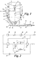
- the apparatus comprises a pressure vessel 1 which is adapted to contain up to a level 2 a blasting mixture 3 of a particulate material and a liquid, typically water or a water based blasting solution, such as a rust inhibiting solution.
- the vessel 1 is provided with an inlet 4, which is defined centrally at the base of a filling hopper 5 located at the top of the vessel 1, and with an outlet 6, which is disposed at the central portion of the bottom of the vessel 1.
- the wall of the lower portion 7 of the vessel 1 can either be dished, as shown in Fig.
- a dished shape is preferable when using fine particulate materials whereas a conical shape is better for use with coarser or denser media such as sand and grit.
- the inlet 4 of the vessel 1 can be closed by an air lock valve 8, for example a mushroom-type valve, which is closed on the application thereto of pressurized air.
- the outlet 6 is also provided with a valve 9 located outside the vessel 1.
- the apparatus is provided with pressurized air as its operational or motive fluid from a pressurized air source, such as an air compressor (not shown), via a control circuit, which is shown in detail in Fig. 2.
- Air under pressure is delivered from the source to a single air inlet 14 for the system and thence to an inlet port of a control valve 15.
- the control valve 15 comprises two outlet ports, the outflows from which are connected by a conduit 15a, which may comprise an external connection, as shown in Fig. 1 in hidden detail, or be within the body of the valve 15.
- the pressurized air from the source can flow through a first outlet port via a pipe 16 into the interior of the vessel 1 and through a second outlet port into a delivery line 17.
- the pipe 16 delivers the pressurized air into the vessel 1 immediately below the air lock valve 8 whereby the valve 8 is closed and the vessel 1 is then pressurized by the air flow. It will be appreciated that the pipe 16 delivers the pressurized air into the vessel above the level 2 of the blasting mixture 3, which is behind the mixture 3 in terms of its outflow from the vessel 1 through the bottom outlet 6.
- the delivery line 17 comprises a further valve 18 and is connected to an abrasive blasting hose 19 and nozzle 20 by a bayonet joint connection as indicated at 21.
- the outlet 6 of the vessel 1 communicates with the delivery line 17 via the valve 9 whereby when the valve 9 is open and pressurized air is passing along the delivery line 17, the blasting mixture 3 within the vessel 1 is entrained by the air flowing along the line 17 and dispersed into the fluid flow for blasting through the nozzle 20.
- a dead-man's control handle 25 is preferably connected to the delivery nozzle 20, but could be located elsewhere such as attached to an operative's body, and is separately supplied with pressurized air from the air inlet 14.
- the control handle 25 is operationally linked to the control valve 15 so that release of the handle 25 closes the control valve 15 to halt the blasting operation whereas squeezing the handle signals the control valve 15 to open, as is described below.
- the control handle 25 is supplied with pressurized air via the inlet 14 from the source along a supply line 26 via a water filter 27, a control valve 28, which comprises the main on/off air control for the apparatus, a flow regulator 29 and a pressure regulator 30.
- Pressurized air is also injected into the lower portion of the vessel 1 to agitate the blasting mixture 2 by an injection means 31 comprising a non-return valve 32 and an egress means such as an agitation coil 33, as shown in Figs. 1 and 3, or a nozzle.
- An injection means 31 comprising a non-return valve 32 and an egress means such as an agitation coil 33, as shown in Figs. 1 and 3, or a nozzle.
- a metering flow valve (not shown) could also be included between the non-return valve 32 and the egress means.
- the purpose of the injection means 31 is to agitate the blasting mixture 3 to keep the particulate material in suspension in the liquid. However, it is important that this agitation takes place without creating turbulence in the vessel 1 which would inhibit the smooth flow of blasting mixture 3 out of the outlet 6 and into the entraining fluid in the delivery line 17.
- the agitation coil 33 or nozzle can be specifically adapted according to the type of particulate material to be used. If fine particulate materials with diameters from 150 microns down to 5 microns are used then an agitation coil 33 similar to the one shown in Figs. 1 and 3 can be used.
- the coil 33 is looped around the outlet 6 at the base of the vessel 1 and is provided with a series of spaced output ports 34 through which the pressurized air supplied to the coil 33 is injected into the vessel 1.
- the ports 34 can be provided with air outlet nozzles (not shown).
- the agitation caused in the blasting mixture 2 by the air egressing from the ports 34 in the coil 33 produces an even mix of the particulate material with the liquid wherein the particles form a suspension in the liquid and each individual particle is enveloped in a coating of liquid.
- the agitation created is sufficient for the blasting mixture 3 to be fluidized so that it flows smoothly through the outlet 6 and the outlet valve 9 into the entraining flow in the delivery line 17.
- An even mix is also important to provide a smooth and even delivery of the blasting material to the work surface, which is important from the point of view of achieving an even finish.
- the outlet 6 is provided with an automatic valve arrangement, as indicated generally at 35 in Fig. 1.
- the valve arrangement 35 comprises an upper first rod 36 which is connected at its upper end to the air lock valve 8 and at its lower end to a flexible connector 37, such as a piece of rubber or the like.
- a lower second rod 38 is connected at its upper end to the connector 37 and at its lower end to a bush 39 which forms a valve member that can obturate the outlet 6.
- the outlet 6 itself comprises a seating 40, which may be made of plastics or of metal, against which the bush 39 can seat, and which defines a cylindrical orifice 41 therethrough that communicates with the valve 9.
- Attached to the bush 39 is a spigot 42, which may comprise the tip of the rod 36 and which penetrates the orifice 41 without closing it.
- the air lock valve 8 When the vessel 1 is pressurized by the passage of air along the pipe 16, the air lock valve 8 is raised to close the inlet 4. Raising of the valve 8 also causes the upper rod 36 to be raised and thereby the lower rod 38 to be raised, lifting the bush 39 off the seating 40 to open the outlet 6. However, the tip of the spigot 42 remains within the inner end of the orifice 41. Thereafter, when pressurized air is injected into the blasting mixture through the agitation coil 33, the agitation of the mixture causes vibration of the lower rod 38, which can move from side to side independently of the upper rod 36 by virtue of the flexible connector 37.
- the spigot 42 thereby also vibrates within the orifice 41 and this prevents the particulate material from being deposited out of the liquid around and in the orifice 41 and ensures that it stays well mixed with the liquid as it egresses from the outlet 6.
- the air lock valve 8 falls, opening the inlet 4 and lowering the rods 36 and 38 so that the bush 39 contacts the seating 40, closing the outlet 6. This then prevents the orifice 41 from becoming plugged with particulate material.
- the tip of the lower rod 38 can be tapered so that in the lower position of the valve arrangement 35 it acts as a stopper in the orifice 41, the bush 39 being omitted from the arrangement 35, and in the upper position of the arrangement 35 just penetrates the orifice 41 without closing it.
- Air is supplied to the non-return valve 32 of the injection means 31 from the source via the inlet 14 through the water filter 27 and a bias controller or manostat 43.
- the function of the manostat 43 is most important as it must ensure that the pressure of the pressurized fluid entering the vessel 1 through the injection means 31 is always maintained at a predetermined higher level than the pressure of the pressurized fluid directed into the vessel 1 through the pipe 16.
- the manostat 43 is connected via a sensing line 44 to the control valve 15 and to the delivery line 26 for the control handle 25 and can adjust the pressure of the air output to the pipe 16 and the delivery line 17 by the control valve 15.
- the on/off valve 28 and the valves 15, 18 and 23 are closed and the liquid inlet and outlet valves 11 and 13 are opened.
- a water or another liquid supply is connected to the inlet 10 and the vessel 1 is then filled with liquid until liquid emanates from the outlet 12.
- the valves 11 and 13 are then closed.
- the source of pressurized fluid typically air, is then connected to the air inlet 14 of the apparatus. This air will pass through the water filter 27 and the manostat 43 into the injection means 31 and thence into the base of the vessel where it will emanate into the liquid therein through the agitation coil 33.
- a predetermined quantity of particulate blasting medium is then introduced into the vessel 1 via the hopper 5 through the inlet 4.
- the level of the blasting mixture 3 within the vessel 1 is then raised typically to the level 2, which is below the bottom of the air lock valve 8.
- the level of the blasting mixture 3 within the vessel 1 is then raised typically to the level 2, which is below the bottom of the air lock valve 8.
- the main on/off valve 28 is opened by being switched to the "on" position. This allows pressurized air to move through the flow regulator 29, the pressure regulator 30 and then along the supply line 26 to exit from the operative's control handle 25. Valves 9 and 18 are then opened.
- the increased air pressure in the sensing line 44 is also detected by the manostat 43 which controls the air pressures to ensure that air entering the vessel 1 via the non-return valve 32 of the injection means 31 is always kept at a higher pressure than the air entering the vessel 1 through the pressurizing pipe 16. This ensures that pressurized air continues to enter the vessel 1 through the agitation coil 33 via the non-return valve 32 to keep the blasting mixture 3 in constant agitation. This air bubbles up through the blasting mixture and collects at the top of the vessel 1. However, because the pressure of this air is greater than that of the air in the pipe 16, the air entering the vessel 1 in this way will then travel down the pipe 16, through the conduit 15a and into the delivery line 17, thus reversing the initial flow of air through the pipe 16.
- the constant flow of pressurized air into the vessel is disposed of in a highly efficient and cost effective way without the need for pressure-reducing or blowoff valves to be employed.
- the manostat 43 is therefore set to maintain a fairly low pressure difference of approximately 0.3 bar (approximately 34.5 x 10³ pascals or 5 psi), or lower, if possible.
- the effect of the air emanating from the agitation coil 33, which mixes the blasting mixture 3 under pressure, is to coat each particle of the particulate medium with a film of liquid.
- This in itself has a beneficial effect on the blasting process as the momentum of each coated particle blasted from the nozzle 20 is thereby increased and results in a more efficient cleaning action.
- fine particulate materials such as the calcium carbonate particles and the like as mentioned above, it is believed that the film of water coating each particle enables the particle to roll over the surface being blasted to create a light scouring action.
- the surface deposits are therefore lifted from the substrate before breaking up and being washed away by the liquid in the blast stream.
- Such particles typically have a rounded appearance, which aids the surface action, and a hardness of between 2.5 and 3.5 mohs in order to prevent damage to the underlying substrate.
- silica sand has a hardness of 6 mohs.
- the increased efficiency of the blasting process owing to the coating of the particulate material with a water film means that far less particulate material is required than would be the case in a conventional blasting process.
- a reduction of between 12% and 48% with the norm in the upper half of the range, i.e. between 30% and 45% can be achieved. This means that a blasting operation can be carried out costing less than would otherwise be the case and also means that afterwards less clearing up of the used particulate material is necessary, again saving money.
- the agitation produced in the blasting mixture 3 in the vessel 1 also causes the lower rod 38 of the automatic valve arrangement 35 to vibrate.
- the spigot 42 which remains partially in the orifice 41 also vibrates and assists with the mixing of the liquid and the particulate medium at this point. This has the benefits of preventing dewatering or settling of the particulate medium inside the orifice 41 and of assisting with a smooth flow of the blasting mixture 3 down into the entraining fluid.
- blasting liquid such as water
- opening valve 23 as determined by the operative.
- the operative releases the handle 25, which allows pressurized air to escape along the line 26 through the -control handle 25, reduces the pressure in the sensing line 44 and thereby causes the control valve 15 to shut off the main air flow from the source 14.
- the pressurized air within the vessel 1 is then vented through the valve 15 and the air lock valve 8 falls, at the same time shutting off the flow of blasting mixture 3 through the outlet 6 by means of the valve arrangement 35.
- a wash-down operation can now be initiated by closing valve 9, opening valve 23 and then closing the control handle 25. This causes the control valve 15 to allow pressurized air again to pass through into the delivery line 17, which sucks water in through the valve 23 and blasts it out through the nozzle 20.
- the object of the blasting operation is thereby cleaned of any remaining particulate material and blasting liquid, if not water, and the delivery line beneath the vessel 1 and the blasting nozzle 20 are flushed out.
- valve 15 can again be released, which will cause valve 15 to close to shut of the air flow through the nozzle 20 once more and the whole apparatus can then be closed down by switching the on/off valve 28 to the "off" position and closing the valve 23.
- pressurized fluid control circuit shown in Fig. 2. can be varied by, for example, replacing the single line feed 26 to the control handle 25 by a twin line with a bleed-off point to line 44 to allow correct sensing.
- Tuning the control circuit is accomplished as follows. First, the air regulator 29 should be fully opened to allow excess air into the line 26. The control handle 25 should then be fully opened to simulate a "close down" situation. The vessel 1 will not exhaust at this point because the control handle 25 will not allow sufficient air to escape so as to reduce the pressure in the line 44 to activate the control valve 15. However, by then gradually closing the air flow regulator 29 until the quantity of air passing through is reduced to a level at which it is all dissipated through the control handle 25, the pressure in the line 44 is reduced. This is sensed by the control valve 15, which in turn causes the vessel 1 to be exhausted.
Landscapes
- Engineering & Computer Science (AREA)
- Mechanical Engineering (AREA)
- Nozzles (AREA)
Claims (11)
- Schleuderstrahleinrichtung umfassend:dadurch gekennzeichnet, dasseinen Behälter (1), der adaptiert, ist ein partikuläres Schleuderstrahlmedium und eine Flüssigkeit zu beinhalten und der einen Einlass (4) und einen unteren Auslass (6) einschließt;eine Förderleitung (17), entlang der eine mitreißende Druckflüssigkeit ab einer Quelle gespeist werden kann und mit der die Innenseite des Behälters (1) durch den Auslass (6) kommuniziert, mit dessen Hilfe ein Druckflüssigkeitsstrom entlang der Förderleitung (17) den Inhalt (3) des Behälters (1) zur Feinverteilung in den Flüssigkeitsstrom in die Förderleitung (17) zum Strahlen mitreißen kann;ein Druckbeaufschlagungsmittel (15, 16), um Druckflüssigkeit ab der Quelle in den Behälter (1) hinter seinen Inhalt (3) hinsichtlich seines Inhaltsausflusses aus dem Behälter (1) durch den unteren Auslass (6) zu lenken;ein Einspritzmittel (31,32,33,34) zum Einspritzen von Druckflüssigkeit in den unteren Teil (7) des Behälters (1) in den Inhalt (3) des Behälters (1), um den Inhalt (3) zu durchrühren; undein Steuermittel (43), um den Druck im Behälter (1) zu steuern und sicherzustellen, dass während des Schleuderstrahlvorgangs der Druck der in den Behälter (1) durch die Einspritzmittel (31,32,33,34) eintretenden Druckflüssigkeit immer auf einem höheren Niveau als der Druck der durch das Druckbeaufschlagungsmittel (15,16) in den Behälter (1) geleiteten Druckflüssigkeit gehalten wird; und
das Druckbeaufschlagungsmittel (15,16) ein Steuerventil (15) aufweist, das eine erste Auslassöffnung, durch welche die Druckflüssigkeit in die Förderleitung (17) fließen kann, und eine zweite Auslassöffnung definiert, durch welche die Druckflüssigkeit in den Behälter (1) fließen kann, um das Innere des Behälters (1) unter Druck zu setzen, wobei die ersten und zweiten Auslassöffnungen durch eine Leitung (15a) verbunden sind, mit deren Hilfe während des Schleuderstrahlvorgangs, falls der Druck innerhalb des Behälters (1) den Druck der durch die zweite Auslassöffnung fließenden Druckflüssigkeit übersteigt, der Druckflüssigkeitsstrom umkehren und aus dem Inneren des Behälters (1) durch die Leitung (15a) und in den Strom der aus der ersten Auslassöffnung austretenden Druckflüssigkeit in die Förderleitung (17) gelangen kann. - Schleuderstrahleinrichtung nach Anspruch 1, dadurch gekennzeichnet, dass das Steuermittel (43) ein "Manostat" aufweist, das an das Steuerventil (15) und an die Einspritzmittel (31,32,33,34) angeschlossen ist, und das ermöglicht, eine vorbestimmte Druckdifferenz zwischen der in den Behälter (1) durch die Einspritzmittel (31,32,33,34) eintretenden Druckflüssigkeit und dem Druck der durch das Druckbeaufschlagungsmittel (15, 16) in den Behälter (1) geleiteten Druckflüssigkeit beizubehalten.
- Schleuderstrahleinrichtung nach Anspruch 1 oder Anspruch 2, dadurch gekennzeichnet, dass die Förderleitung (17) in einer Strahldüse (20) mit einem Steuergriff (25) endet, die mit Druckflüssigkeit ab der Quelle versorgt wird und die mit dem Steuermittel (43) und dem Steuerventil (15) verbunden ist, mit dessen Hilfe ein Bediener das Steuerventil öffnen und danach den Strom der Druckflüssigkeit durch die Düse (20) durch Variieren des Stroms der Druckflüssigkeit durch den Steuergriff (25) regeln kann.
- Schleuderstrahleinrichtung nach einem der Ansprüche 1 bis 3, wobei der Einlass (4) in den Behälter (1) mit einem Druckluft-Halteventil (8) versehen ist, das durch die Zufuhr von Druckflüssigkeit darauf von innerhalb des Behälters (1) durch das Druckbeaufschlagungsmittel (15,16) geschlossen wird und dadurch gekennzeichnet ist, dass der Auslass (6) im Behälter (1) mit einem Ventilmittel (35) versehen ist, das mit dem Druckluft-Halteventil (8) so verbunden ist, dass das Schließen des Druckluft-Halteventils (8) das Öffnen des Ventilmittels (35) am Auslass des Behälters (1) und umgekehrt bewirkt.
- Schleuderstrahleinrichtung nach Anspruch 4, dadurch gekennzeichnet, dass der Auslass (6) aus dem Behälter (1) eine Öffnung (41) umfasst und das Ventilmittel (35) für den Auslass (6) einen Zapfen (42) umfasst, der in die Öffnung (41) eingeschoben wird, wobei die Spitze des Zapfens (42) innerhalb der Öffnung (41) verbleibt, wenn das Ventilmittel (35) geöffnet wird, um den Ausfluss des Inhalts (3) des Behälters (1) zu gestatten.
- Schleuderstrahleinrichtung nach Anspruch 4 oder Anspruch 5, dadurch gekennzeichnet, dass das Ventilmittel (35) für den Auslass (6) durch eine elastische Kupplung (37) mit dem Druckluft-Halteventil (8) verbunden ist, mit deren Hilfe, wenn das Ventilmittel (35) geöffnet ist, das Bewegen des Inhalts (3) des Behälters (1) das Bewegen der Spitze des Zapfen (42) innerhalb der Öffnung (41) bewirkt.
- Schleuderstrahleinrichtung nach einem der Ansprüche 1 bis 6, dadurch gekennzeichnet, dass das Einspritzmittel (31, 32, 33, 34) ein Rückschlagventil (32) umfasst, das an ein Ausgangsmittel (33,34) angeschlossen ist, das sich innerhalb des Behälters (1) in der Nähe des Auslasses (6) des Behälters (1) befindet.
- Schleuderstrahleinrichtung nach Anspruch 7, dadurch gekennzeichnet, dass das Ausgangsmittel (33,34) eine perforierte Schlange umfasst, die um den Auslass (6) des Behälters (1) gewickelt ist.
- Schleuderstrahleinrichtung nach einem der Ansprüche 1 bis 8, dadurch gekennzeichnet, dass die Förderleitung (17) mit einer Flüssigkeitszufuhr (22) stromaufwärts des Auslasses (6) vom Behälter, aber stromabwärts des Druckbeaufschlagungsmittels (15,16) verbunden ist, mit deren Hilfe sich Flüssigkeit in den Strom der mitreißenden Flüssigkeit injizieren lässt, welche die Förderleitung (17) hinunterströmt.
- Verwendung einer Schleuderstrahleinrichtung nach Anspruch 1 zum Strahlen einer Mischung eines partikulären Strahlmediums und einer Flüssigkeit durch
Mitreißen der Mischung in einem Strom von Druckflüssigkeit in die Förderleitung (17) bei gleichzeitiger Druckbeaufschlagung des Inneren des Behälters (1), indem ein Strom der Druckflüssigkeit ab der Quelle in den Behälter (1) hinter seinen Inhalt (3) hinsichtlich seines Inhaltsausflusses aus dem Behälter (1) geleitet wird;
Einspritzen eines Stroms von Druckflüssigkeit in den Inhalt (3) des Behälters (1), um den Inhalt (3) zu bewegen;
Steuern des Drucks innerhalb des Behälters (1) durch Sicherstellen, dass während des Schleuderstrahlvorgangs der Druck der in den Inhalt (3) des Behälters (1) eingespritzten Druckflüssigkeit immer auf einem höheren Niveau als der Druck der Druckflüssigkeit gehalten wird, die in den Behälter (1) hinter seinen Inhalt (3) geleitet wird; und
dadurch gekennzeichnet, dass,
wenn der Druck innerhalb des Behälters (1) den Druck der Druckflüssigkeit übersteigt, sich der Strom der Druckflüssigkeit in den Behälter umkehren lässt und aus dem Innern des Behälters (1) durch eine Leitung (15a) und in den Strom der Druckflüssigkeit in der Förderleitung (17) geleitet wird. - Verwendung einer Schleuderstrahleinrichtung nach Anspruch 10, dadurch gekennzeichnet, dass das partikuläre Medium ein Medium umfasst, das im wesentlichen wenigstens eins aus Calciumcarbonat, Calcium-Magnesiumcarbonat, Calciumoxid, Calciumhydrogencarbonat, Calcium-Magnesiumcarbonat, Magnesiumoxid und Magnesiumsulfat, oder kalzinierte Soda, einen Olivinsand oder Granat umfasst.
Applications Claiming Priority (3)
| Application Number | Priority Date | Filing Date | Title |
|---|---|---|---|
| GBGB9904872.0A GB9904872D0 (en) | 1999-03-04 | 1999-03-04 | Abrasive blasting apparatus |
| GB9904872 | 1999-03-04 | ||
| PCT/GB2000/000759 WO2000051787A1 (en) | 1999-03-04 | 2000-03-03 | Abrasive blasting apparatus |
Publications (2)
| Publication Number | Publication Date |
|---|---|
| EP1075352A1 EP1075352A1 (de) | 2001-02-14 |
| EP1075352B1 true EP1075352B1 (de) | 2003-05-02 |
Family
ID=10848870
Family Applications (1)
| Application Number | Title | Priority Date | Filing Date |
|---|---|---|---|
| EP00907777A Expired - Lifetime EP1075352B1 (de) | 1999-03-04 | 2000-03-03 | Schleuderstrahleinrichtung |
Country Status (4)
| Country | Link |
|---|---|
| EP (1) | EP1075352B1 (de) |
| AU (1) | AU2925400A (de) |
| GB (1) | GB9904872D0 (de) |
| WO (1) | WO2000051787A1 (de) |
Cited By (2)
| Publication number | Priority date | Publication date | Assignee | Title |
|---|---|---|---|---|
| WO2012009325A1 (en) * | 2010-07-13 | 2012-01-19 | Keith Eliason | Wet abrasive blasting system and method |
| CN107847985A (zh) * | 2015-07-16 | 2018-03-27 | 固瑞克明尼苏达有限公司 | 具有固定罐压的水汽喷砂系统 |
Families Citing this family (9)
| Publication number | Priority date | Publication date | Assignee | Title |
|---|---|---|---|---|
| GB2382317B (en) | 2001-11-22 | 2004-05-12 | Quill Internat Ind Plc | Abrasive blasting apparatus |
| CA2473732A1 (en) * | 2002-01-24 | 2003-07-31 | Exa Sa | A process for treating a surface |
| WO2004084851A2 (en) * | 2003-03-24 | 2004-10-07 | Exa Sa | A treatment composition |
| GB2386853A (en) * | 2002-03-27 | 2003-10-01 | Mos Cold Cutting Systems Ltd | A feeder device for a high pressure hydraulic cutting system pressure vessel |
| JP2010192673A (ja) * | 2009-02-18 | 2010-09-02 | Tokyo Electron Ltd | 基板洗浄方法、基板洗浄装置、制御プログラム及びコンピュータ読取可能な記憶媒体 |
| US10076823B2 (en) * | 2010-07-13 | 2018-09-18 | Graco Minnesota Inc. | Wet abrasive blasting system and method |
| EP3215314A4 (de) | 2014-11-06 | 2018-05-30 | Graco Minnesota Inc. | Steuerung von nassschleifstrahlern |
| CN108481210A (zh) * | 2018-05-09 | 2018-09-04 | 中船澄西船舶修造有限公司 | 一种水雾磨料喷砂机 |
| CN114211407A (zh) * | 2022-01-28 | 2022-03-22 | 荣成新霞修船有限公司 | 加压水加砂除锈设备 |
Family Cites Families (9)
| Publication number | Priority date | Publication date | Assignee | Title |
|---|---|---|---|---|
| FR1121042A (fr) * | 1955-02-01 | 1956-07-19 | Luchaire Sa | Appareil permettant le sablage au moyen de sable humide |
| DE3232994A1 (de) * | 1982-09-04 | 1984-03-08 | Surface Export AG, 8876 Filzbach | Schleuderstrahlmaschine |
| GB2196279B (en) * | 1986-10-17 | 1990-08-01 | Rhoderick Jonathan Spenc Baker | Pressurized blasting machine |
| JP2963158B2 (ja) * | 1990-07-24 | 1999-10-12 | 株式会社不二精機製造所 | スラリイ圧送式ブラスト装置 |
| DE9103701U1 (de) * | 1991-03-26 | 1991-07-04 | Abrex Oberflächentechnik GmbH, 2330 Windeby | Feuchtsandstrahler |
| JPH06102299B2 (ja) * | 1991-05-20 | 1994-12-14 | 株式会社不二精機製造所 | 湿式ブラストにおけるスラリー供給装置 |
| DE9106342U1 (de) * | 1991-05-23 | 1991-10-24 | Abrex Oberflächentechnik GmbH, 2330 Windeby | Feuchtsandstrahler |
| DE4335382C2 (de) * | 1993-10-16 | 1997-05-07 | Abrex Oberflaechentechnik Gmbh | Strahlgerät |
| US5531634A (en) * | 1995-02-03 | 1996-07-02 | Schott; Paul | Method of using an abrasive material for blast cleaning of solid surfaces |
-
1999
- 1999-03-04 GB GBGB9904872.0A patent/GB9904872D0/en not_active Ceased
-
2000
- 2000-03-03 EP EP00907777A patent/EP1075352B1/de not_active Expired - Lifetime
- 2000-03-03 AU AU29254/00A patent/AU2925400A/en not_active Abandoned
- 2000-03-03 WO PCT/GB2000/000759 patent/WO2000051787A1/en not_active Ceased
Cited By (4)
| Publication number | Priority date | Publication date | Assignee | Title |
|---|---|---|---|---|
| WO2012009325A1 (en) * | 2010-07-13 | 2012-01-19 | Keith Eliason | Wet abrasive blasting system and method |
| CN107847985A (zh) * | 2015-07-16 | 2018-03-27 | 固瑞克明尼苏达有限公司 | 具有固定罐压的水汽喷砂系统 |
| EP3322545A4 (de) * | 2015-07-16 | 2019-03-27 | Graco Minnesota Inc. | Dampfstrahlsystem mit festem behälterdruck |
| US10875151B2 (en) | 2015-07-16 | 2020-12-29 | Graco Minnesota Inc. | Vapor blast system with fixed pot pressure |
Also Published As
| Publication number | Publication date |
|---|---|
| GB9904872D0 (en) | 1999-04-28 |
| EP1075352A1 (de) | 2001-02-14 |
| AU2925400A (en) | 2000-09-21 |
| WO2000051787A1 (en) | 2000-09-08 |
Similar Documents
| Publication | Publication Date | Title |
|---|---|---|
| EP1075352B1 (de) | Schleuderstrahleinrichtung | |
| EP1450988B1 (de) | Sandstrahlgerät | |
| US4522597A (en) | Equipment and method for delivering an abrasive-laden gas stream | |
| US11548116B2 (en) | Apparatus configured to provide both wet and dry blasting and method for operating such an apparatus | |
| US8500520B2 (en) | System and method for removing a coating from a substrate | |
| US5283991A (en) | Sandblasting method and a moist-sand blasting apparatus | |
| KR100565549B1 (ko) | 연마유체분사시스템 | |
| US5195280A (en) | Abrasive blasting apparatus | |
| JPH10156723A (ja) | 高圧水ジェット利用加工装置 | |
| EP0708699A1 (de) | Strahlvorrichtung mit einstellbarer stärke | |
| EP0358648B1 (de) | Sandstrahleinrichtung | |
| JPS59502138A (ja) | 湿砂を用いるサンドブラスト方法及び該方法を実施する湿式サンドブラスト装置 | |
| NO166397B (no) | Anordning for tilsetning av finfordelt microsilica slurrytil et toerrsproeytebetongmunnstykkes vannroer. | |
| EP3300836B1 (de) | Vorrichtung zum sprühen einer abrasiven mischung auf eine empfindliche oberfläche zum entfernen von schriftzügen, zeichnungen oder graffiti | |
| US20220297264A1 (en) | Apparatus for abrasive cleaning | |
| JPH01288385A (ja) | 管の清掃方法及び装置 | |
| JPH01183369A (ja) | 液体ジェット加工装置の研摩材供給装置 | |
| US11679473B2 (en) | Dry wet blast media blasting system | |
| JPH07121509B2 (ja) | サンドブラスト装置 | |
| JP2589074B2 (ja) | 研摩材とキャリア液体の混合物の噴射を生じさせる装置 | |
| JPS6028515Y2 (ja) | 液体処理用撹拌装置 | |
| PL135482B1 (en) | Method of producing a wet abrasive jet for pneumatic samdblast machines | |
| JPH0788769A (ja) | サンドブラスト装置 | |
| JPH11114831A (ja) | 噴射量を少量に制御可能な直圧式ブラスト加工装置 | |
| JP2006026615A (ja) | 気液混合流噴射装置 |
Legal Events
| Date | Code | Title | Description |
|---|---|---|---|
| PUAI | Public reference made under article 153(3) epc to a published international application that has entered the european phase |
Free format text: ORIGINAL CODE: 0009012 |
|
| 17P | Request for examination filed |
Effective date: 20001123 |
|
| AK | Designated contracting states |
Kind code of ref document: A1 Designated state(s): GB GR |
|
| RAP1 | Party data changed (applicant data changed or rights of an application transferred) |
Owner name: GAGEMARK LIMITED Owner name: NICHOLSON, JOSEPHINE ANNE |
|
| 17Q | First examination report despatched |
Effective date: 20011211 |
|
| RAP1 | Party data changed (applicant data changed or rights of an application transferred) |
Owner name: QUILL INTERNATIONAL INDUSTRIES PLC Owner name: NICHOLSON, JOSEPHINE ANNE |
|
| GRAG | Despatch of communication of intention to grant |
Free format text: ORIGINAL CODE: EPIDOS AGRA |
|
| GRAG | Despatch of communication of intention to grant |
Free format text: ORIGINAL CODE: EPIDOS AGRA |
|
| GRAH | Despatch of communication of intention to grant a patent |
Free format text: ORIGINAL CODE: EPIDOS IGRA |
|
| GRAH | Despatch of communication of intention to grant a patent |
Free format text: ORIGINAL CODE: EPIDOS IGRA |
|
| GRAA | (expected) grant |
Free format text: ORIGINAL CODE: 0009210 |
|
| AK | Designated contracting states |
Designated state(s): GB GR |
|
| REG | Reference to a national code |
Ref country code: GB Ref legal event code: FG4D |
|
| REG | Reference to a national code |
Ref country code: GR Ref legal event code: EP Ref document number: 20030402941 Country of ref document: GR |
|
| PLBE | No opposition filed within time limit |
Free format text: ORIGINAL CODE: 0009261 |
|
| STAA | Information on the status of an ep patent application or granted ep patent |
Free format text: STATUS: NO OPPOSITION FILED WITHIN TIME LIMIT |
|
| PGFP | Annual fee paid to national office [announced via postgrant information from national office to epo] |
Ref country code: GR Payment date: 20040329 Year of fee payment: 5 |
|
| 26N | No opposition filed |
Effective date: 20040203 |
|
| PG25 | Lapsed in a contracting state [announced via postgrant information from national office to epo] |
Ref country code: GR Free format text: LAPSE BECAUSE OF NON-PAYMENT OF DUE FEES Effective date: 20051004 |
|
| PGFP | Annual fee paid to national office [announced via postgrant information from national office to epo] |
Ref country code: GB Payment date: 20190227 Year of fee payment: 20 |
|
| REG | Reference to a national code |
Ref country code: GB Ref legal event code: PE20 Expiry date: 20200302 |
|
| PG25 | Lapsed in a contracting state [announced via postgrant information from national office to epo] |
Ref country code: GB Free format text: LAPSE BECAUSE OF EXPIRATION OF PROTECTION Effective date: 20200302 |