EP1075785A1 - Cultivateur de taille réduite - Google Patents
Cultivateur de taille réduite Download PDFInfo
- Publication number
- EP1075785A1 EP1075785A1 EP00117111A EP00117111A EP1075785A1 EP 1075785 A1 EP1075785 A1 EP 1075785A1 EP 00117111 A EP00117111 A EP 00117111A EP 00117111 A EP00117111 A EP 00117111A EP 1075785 A1 EP1075785 A1 EP 1075785A1
- Authority
- EP
- European Patent Office
- Prior art keywords
- transmission mechanism
- power transmission
- manipulating handle
- small
- tilling
- Prior art date
- Legal status (The legal status is an assumption and is not a legal conclusion. Google has not performed a legal analysis and makes no representation as to the accuracy of the status listed.)
- Granted
Links
- 230000005540 biological transmission Effects 0.000 claims abstract description 123
- 210000000078 claw Anatomy 0.000 claims abstract description 59
- 230000035939 shock Effects 0.000 claims abstract description 45
- 238000013016 damping Methods 0.000 claims description 90
- 230000033001 locomotion Effects 0.000 claims description 23
- 238000013459 approach Methods 0.000 claims description 7
- 239000004575 stone Substances 0.000 abstract description 13
- 239000007787 solid Substances 0.000 abstract description 11
- 239000000725 suspension Substances 0.000 description 22
- 230000004048 modification Effects 0.000 description 16
- 238000012986 modification Methods 0.000 description 16
- 238000006243 chemical reaction Methods 0.000 description 13
- 238000010276 construction Methods 0.000 description 9
- 230000005484 gravity Effects 0.000 description 9
- 125000006850 spacer group Chemical group 0.000 description 5
- 230000000750 progressive effect Effects 0.000 description 4
- 239000002689 soil Substances 0.000 description 3
- 229910000831 Steel Inorganic materials 0.000 description 2
- 230000000903 blocking effect Effects 0.000 description 2
- 239000000470 constituent Substances 0.000 description 2
- 238000006073 displacement reaction Methods 0.000 description 2
- 230000035807 sensation Effects 0.000 description 2
- 239000010959 steel Substances 0.000 description 2
- 238000005452 bending Methods 0.000 description 1
- 150000001875 compounds Chemical class 0.000 description 1
- 230000000694 effects Effects 0.000 description 1
- 239000002828 fuel tank Substances 0.000 description 1
- 239000000463 material Substances 0.000 description 1
- 230000002093 peripheral effect Effects 0.000 description 1
Images


Classifications
-
- A—HUMAN NECESSITIES
- A01—AGRICULTURE; FORESTRY; ANIMAL HUSBANDRY; HUNTING; TRAPPING; FISHING
- A01B—SOIL WORKING IN AGRICULTURE OR FORESTRY; PARTS, DETAILS, OR ACCESSORIES OF AGRICULTURAL MACHINES OR IMPLEMENTS, IN GENERAL
- A01B33/00—Tilling implements with rotary driven tools, e.g. in combination with fertiliser distributors or seeders, with grubbing chains, with sloping axles, with driven discs
- A01B33/02—Tilling implements with rotary driven tools, e.g. in combination with fertiliser distributors or seeders, with grubbing chains, with sloping axles, with driven discs with tools on horizontal shaft transverse to direction of travel
- A01B33/028—Tilling implements with rotary driven tools, e.g. in combination with fertiliser distributors or seeders, with grubbing chains, with sloping axles, with driven discs with tools on horizontal shaft transverse to direction of travel of the walk-behind type
Definitions
- the present invention relates to a small-sized tiller and, more particularly, to a small-sized tiller which can easily be steered even when its tilling claw runs onto hard ground or a solid object such as a stone buried in ground during tilling work.
- the small-sized tiller has a transmission fitted to the lower portion of an engine, a rotating shaft fitted to the lower portion of the transmission, and plural tilling claws fitted to the rotating shaft in such a manner as to be spaced apart from one another at predetermined intervals.
- the small-sized tiller runs while effecting tilling by means of the plural claws.
- This small-sized tiller has a manipulating handle fitted to the rear upper portion of the transmission.
- a resistance bar is fitted to the transmission, and extends downwardly from the rear of the transmission. The resistance bar is inserted into ground during tilling work.
- the tilling claws strike on a hard solid object such as a stone during tilling work using the small-sized tiller, the tilling claws ride onto the solid object and the tilling shaft bounds upwardly, causing a phenomenon which causes the small-sized tiller to bound owing to a tilling reaction force. Shock energy at this time conducts from the tilling claws to the transmission, the engine and the manipulating handle via the rotating shaft.
- the tiller will bound on its right or left side and will lose the balance between the right and left sides.
- the operator needs to adjust the length by which to insert the resistance bar into ground, by appropriately setting the height at which to fit the resistance bar, according to the conditions of soil, or (2) the operator needs to adjust the load under which to insert the resistance into ground, by applying an adequate downward manipulating force to the manipulating handle during tilling work. In this way, it is possible to adjust the resistance force of the resistance bar against the shock, energy.
- the present invention has been made in view of the above-described points, and aims to provide a small-sized tiller which is at all times easy to steer and enables far easier tilling work.
- a small-sized tiller characterized by a power source, a power transmission mechanism for transmitting a rotational driving force of the power source to a tilling shaft, plural tilling claws fitted to the tilling shaft and arranged to cause the tiller to run, by rotating while tilling ground, a resistance bar to be inserted in ground, and a manipulating handle which is swingably fitted via a pivot to a rear portion of the power source or a rear portion of the power transmission mechanism.
- the manipulating handle is upwardly and downwardly swingably fitted to the rear portion of the power source or the rear portion of the power transmission mechanism.
- a damping member for effecting damping when the power source and the power transmission mechanism swing upwardly or downwardly with respect to the manipulating handle is interposed between the power source or the power transmission mechanism and the manipulating handle.
- a first link is upwardly and downwardly swingably fitted to the rear portion of the power source or the rear portion of the power transmission mechanism, while a second link is forwardly and rearwardly swingably fitted to the manipulating handle, the first link being connected to the second link to constitute a link mechanism which can be bent according to a forward or rearward swing of the power source and the power transmission mechanism.
- One end of a damping member is forwardly and rearwardly swingably connected to a connection portion between the first and second links, while the other end of the damping member is forwardly and rearwardly swingably connected to the manipulating handle, to enable the proportion of the stroke of the damping member per predetermined amount of swing to vary to a larger extent as the power source and the power transmission mechanism swing in a direction in which the power source and the power transmission mechanism approach the manipulating handle.
- the resistance bar may be fitted to extend downwardly from the manipulating handle or to extend downwardly from the rear portion of the power transmission mechanism.
- the damping member for effecting damping when the power source and the power transmission mechanism swing upwardly or downwardly with respect to the manipulating handle be interposed between the power source or the power transmission mechanism and the manipulating handle, because when the power source and the power transmission mechanism swing upwardly or downwardly with respect to the manipulating handle, shock energy can be fully absorbed by the damping member.
- a suspension made of the link mechanism and the damping member is a progressive suspension in which the proportion of the stroke of the damping member per predetermined amount of swing varies to a larger extent as the power source and the power transmission mechanism swing in the direction in which they approach the manipulating handle.
- the damping member absorbs a smaller shock energy with a smaller stroke and a larger shock energy with a larger stroke. Accordingly, the damping member can effectively absorb shock energy.
- the resistance bar extends downwardly from the manipulating handle, during tilling work, the length by which to insert the resistance bar into ground can be adjusted to stabilize a tilling depth, by applying an adequate downward manipulating force to the manipulating handle. Moreover, it is preferable that the resistance bar be extended downwardly from the rear of the power transmission mechanism as described above, because when a bounding phenomenon occurs, the resistance bar is inserted into ground to restrain the swing of the power source and the power transmission mechanism.
- the manipulating handle is fitted via a pivot to the rear of the power source or the rear of the power transmission mechanism so that the portion forward of the pivot can swing rightwardly and leftwardly with respect to the manipulating handle as viewed from the operator, thereby absorbing shock energy.
- the tilling claws, the power source and the power transmission mechanism rotate about the pivot and incline rightwardly or leftwardly with respect to the manipulating handle, thereby absorbing the right and left different tilling reaction forces. Accordingly, the manipulating handle is stable without bounding or inclining, and the operator can steer the small-sized tiller while keeping the balance between the right and left sides of the small-sized tiller.
- a pair of right and left damping members for reducing shock occurring due to the rightward and leftward swing of the portion forward of the pivot are interposed between the power source or the power transmission mechanism and the manipulating handle, whereby shock energy is absorbed by the damping members.
- a pair of right and left arms are respectively extended from the manipulating handle toward the right and left sides of the power source or the right and left sides of the power transmission mechanism, and the right and left sides of the power source or the right and left sides of the power transmission mechanism are respectively connected to the ends of the pair of right and left arms by a pair of right and left links, the pair of right and left damping members being interposed between the pair of right and left links and the manipulating handle to convert a rightward and leftward swinging motion of the power source and the power transmission mechanism into a forward and rearward swinging motion through the pair of right and left links and transmit the forward and rearward swinging motion to the pair of right and left damping members.
- the damping members can be disposed so that they can be expanded and compressed toward the front and the rear of the vehicle body of the small-sized tiller, whereby the small-sized tiller can be made far more compact.
- the resistance bar be extended downwardly from the manipulating handle, because the length by which to insert the resistance bar into ground can be adjusted to stabilize the tilling depth during tilling work, by applying an adequate downward manipulating force to the manipulating handle.
- a small-sized tiller 10 according to a first embodiment of the present invention is provided with an engine 11 as a power source.
- the driving force outputted from the engine 11 rotates a tilling shaft 13 via a power transmission mechanism 12.
- Plural tilling claws 14 and 15 are fitted to the tilling shaft 13 in the state of being spaced apart from one another at predetermined intervals.
- the small-sized tiller 10 runs while tilling ground by means of the rotation of the tilling claws 14 and 15.
- the small-sized tiller 10 has a manipulating handle 40 which extends upwardly rearwardly from the rear of the power transmission mechanism 12.
- a resistance bar 93 is fitted to the manipulating handle 40 in such a manner as to extend downwardly from the lower portion of the manipulating handle 40.
- the manipulating handle 40 is fitted for upward and downward swinging movement about a pivot portion 50 which is provided at the rear of the power transmission mechanism 12.
- the power transmission mechanism 12 is a mechanism which transmits the driving force of the engine 11 to the tilling shaft 13, and has plural gears (not shown) which are built in a case 16.
- the resistance bar 93 is inserted into ground to set a tilling depth H for the first and second tilling claws 14 and 15, and produces resistance forces against the advancing forces of the tilling claws 14 and 15.
- reference numeral 21 denotes an engine cover
- reference numeral 22 a cover for blocking the splashing of mud or the like
- reference numeral 23 a vehicle-body guard.
- the engine 11 is disposed along the center line CL of the vehicle body.
- the power transmission mechanism 12 is fitted to the lower portion of the engine 11.
- the tilling shaft 13 is fitted to the lower portion of the power transmission mechanism 12 in such a manner as to extend in the width direction of the tiller 10.
- the plural tilling claws 14 and 15 include the first tilling claws 14 and 14 which are respectively disposed at inward positions adjacent to the vehicle-body center line CL, and the second tilling claws 15 and 15 which are respectively disposed at positions outward of the first tilling claws 14 and 14.
- the plural tilling claws 14 and 15 are fitted to the tilling shaft 13 in such a manner as to be arranged at a predetermined pitch in the longitudinal direction of the tilling shaft 13.
- the manipulating handle 40 is made of a handle post part 42 of inverse U-like shape which has right and left leg portions 41 and 41 at the rear of the power transmission mechanism 12, a vertical handle fitting part 43 which is fixed to the top end of the handle post part 42 along the vehicle-body center line CL, and a handle part 44 of V-like shape which is fitted to the handle fitting part 43.
- reference numeral 24 denotes a fuel tank
- reference numeral 25 an air cleaner
- reference numerals 26 and 26 side disks reference numerals 45 and 45 grips
- reference numeral 46 a clutch lever
- Fig. 3 is a cross-sectional side view of the manipulating-handle fitting structure of the small-sized tiller 10, and shows a specific fitting structure of the manipulating handle 40 and that of the resistance bar 93.
- the fitting structure of the manipulating handle 40 is such that right and left brackets 33R and 33L (only the right one of which is shown in Fig. 3) are fitted to the rear lower portion of the power transmission mechanism 12, and the lower portion of the handle post part 42 is fitted to the rear lower portions of the brackets 33R and 33L so that the handle post part 42 can swing up and down about the pivot portion 50.
- the engine 11 and the power transmission mechanism 12 are fitted for upward and downward swinging movement with respect to the manipulating handle 40.
- the tiller 10 is provided with a suspension 60 which suspends the engine 11 and the power transmission mechanism 12 on the manipulating handle 40.
- the suspension 60 has a structure in which a damping member 64 is interposed between the power transmission mechanism 12 and the manipulating handle 40.
- the damping member 64 is a damper which effects damping when the engine 11 and the power transmission mechanism 12 are swinging up and down with respect to the manipulating handle 40 as described above; for example, an oil damper 66 having a coil spring 65 which can be compressed and expanded toward the front and the rear of the tiller 10.
- Reference numeral 67 denotes a reservoir tank.
- the suspension 60 includes a cross member 61 made of a steel material of L-like cross-sectional shape, and the cross member 61 is passed between the rear upper portions of the respective right and left brackets 33R and 33L.
- the suspension 60 includes an arm 71 which extends rearwardly downwardly from the upper portion of the handle post part 42.
- the arm 71 is upwardly and downwardly swingably fitted to the rear end (the other end) 64b of the damping member 64.
- the front end (one end) 64a of the damping member 64 is upwardly and downwardly swingably fitted to the cross member 61.
- the handle post part 42 is provided with a lower-limit stopper portion 81 and an upper-limit stopper portion 85 in order to determine the swinging range of the handle post part 42 (the swinging range of the engine 11 and the power transmission mechanism 12).
- the lower-limit stopper portion 81 is provided with lower stopper pieces 82 and 82 fitted to the lower ends of the respective brackets 33R and 33L, and abutment pieces 83 and 83 fitted to the lower ends of the respective leg portions 41 and 41 of the handle post part 42.
- the lower-limit swing position of the handle post part 42 is determined by the abutment pieces 83 and 83 being respectively brought into abutment with the lower surfaces of the lower stopper pieces 82 and 82.
- the upper-limit stopper portion 85 has a structure in which a horizontal member 86 is passed between the leg portions 41 and 41 of the handle post part 42 and a positioning bolt 87 is fitted into the horizontal member 86 so that it can be adjusted to move back and forth.
- the upper-limit swing position of the handle post part 42 is determined by the position at which the point of the positioning bolt 87 is brought into abutment with the cross member 61.
- the case 16 of the power transmission mechanism 12 has side fitting bosses 31R and 31L on both right and left sides and a rear fitting boss 32 at its rear end portion.
- Each of the right and left brackets 33R and 33L is a member formed by bending a plate into a crank-like shape in cross section. This one pair of right and left brackets 33R and 33L are respectively fitted to the side fitting bosses 31R and 31L by bolts 34 and 34, and are fastened to the rear fitting boss 32 by one long bolt 35.
- Reference numerals 36 and 36 denote spacers.
- pivot portion 50 for supporting the handle post part 42 for upward and downward swinging movement on the right and left brackets 33R and 33L.
- the pivot portion 50 is provided with a cross pipe 51 which is inserted through the right and left leg portions 41 and 41 of the handle post part 42 and is passed between the right and left brackets 33R and 33L.
- a pipe-like shaft 53 is rotatably inserted in the cross pipe 51 through bushes 52 and 52.
- One long supporting bolt 54 is inserted through the hole of the shaft 53 to fasten together the right and left brackets 33R and 33L and the shaft 53, thereby supporting the handle post part 42 on the right and left brackets 33R and 33L for upward and downward swinging movement about the supporting bolt 54.
- the manipulating handle 40 can be supported at two right and left locations within a large support span. Accordingly, even if an external force acts on the manipulating handle 40 from either side, the manipulating handle 40 does not sway and is kept stable, whereby stable steering can be realized.
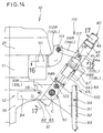
- An arm 91 is fitted to the cross pipe 51 along the vehicle-body center line CL (at the position of the center of gravity G of the entire tiller).
- the arm 91 is extended rearwardly, and a holding pipe 92 which extends vertically (in the direction perpendicular to the surface of the sheet of Fig. 4) is fitted to the rear end of the arm 91.
- the resistance bar 93 is upwardly and downwardly slidably fitted into the holding pipe 92 and is secured by a securing bolt 94.
- Both ends of the cross member 61 are respectively fitted to the right and left brackets 33R and 33L by plural bolts 62.
- a holder 63 having a channel-like shape in cross section is fitted to the upper surface of the cross member 61.
- a front end 64a of the damping member 64 is rotatably fitted to both flanges 63a and 63a of the holder 63 by a connecting bolt 68.
- the damping member 64 is disposed along the vehicle-body center line CL between the right and left leg portions 41 and 41 of the handle post part 42 of inverse U-like shape.
- the fitting position of the front end 64a of the damping member 64 is close to the center of gravity G of the entire tiller.
- Reference numerals 69 and 69 denote spacers.
- the positioning bolt 87 is disposed along the vehicle-body center line CL.
- Fig. 6 shows the state of connection between the damping member 64 and the arm 71.
- a channel-shaped holder 72 having an open bottom is fitted to the rear end of the arm 71 made of a channel steel having an open top by a bolt 73 in such a manner that the channel-shaped holder 72 covers the rear end of the arm 71.
- a rear end 64b of the damping member 64 is rotationally swingably fitted to flanges 72a and 72a of the channel-shaped holder 72 by a connecting bolt 74.
- Reference numerals 75, 76 and 76 denote spacers
- reference numerals 77 and 77 denote collars.
- an operator grips the manipulating handle 49 and starts walking while steering the small-sized tiller.
- the tiller 10 advances and tills ground while rotating the first and second tilling claws 14 and 15 by means of the power transmission mechanism 12 and the tilling shaft 13 by the driving force of the engine 11.
- the tilling depth H for the first and second tilling claws 14 and 15 is set, and resistance forces against the driving forces of the first and second tilling claws 14 and 15 can also be applied to the small-sized tiller 10.
- the swing center C of the manipulating handle 40 i.e., the center of the pivot portion 50, lies in the vicinity of the center of gravity G of the entire tiller.
- the swing center C is set at a position rearwardly away from the center of gravity G by a distance X, and at nearly the same height as the center of gravity G.
- the distance X is set as follows. The distance X is set so that during tilling work, when the resistance bar 93 is inserted into the ground Gr. to produce resistance forces against the tractate forces of the first and second tilling claws 14 and 15, the position of the center of gravity G of the entire tiller travels rearwardly and nearly coincides with the swing center C.
- the fitting position of the front end 64a of the damping member 64 is set to a position nearly directly above the swing center C in the vicinity of the center of gravity G of the entire tiller. It is, therefore, possible to stabilize the running of the small-sized tiller 10, whereby it is possible to improve the straight-running performance and the turning performance of the small-sized tiller 10. Accordingly, it is possible to improve the steering performance of the small-sized tiller 10 to facilitate tilling operation.
- the handle post part 42 is, as shown in Fig. 4, formed into the inverse U-like shape and the power transmission mechanism 12 is fitted in the state of being clamped between the right and left leg portions 41 and 41 by means of the right and left brackets 33R and 33L.
- the load of the manipulating handle 40 that can be supported by the damping member 64 is called “spring borne load”, and a load which acts on the damping member 64, i.e., the load of the engine 11, the power transmission mechanism 12, the tilling shaft 13, the first and second tilling claws 14 and 15 and the like, is called “unsparing load”.
- the value obtained by dividing the unsparing load (numerator) by the spring borne load (denominator) is made small, the vibrations of the first and second tilling claws 14 and 15 are prevented from easily conducting to the manipulating handle 40, whereby superior manipulation sensation can be realized. If this superior manipulation sensation is to be realized, it is preferable to set the spring borne load to a large load.
- the operator can insert the resistance bar 93 integral with the manipulating handle 40 into the ground Gr. by applying a downward manipulating force to the manipulating handle 40. Since the resistance bar 93 which extends downwardly from the manipulating handle 40 is inserted in the ground Gr., the resistance bar 93 has a resistance force in a direction perpendicular to the axis of the resistance bar 93. Therefore, the resistance bar 93 and the manipulating handle 40 are stable in the forward, rearward, rightward and leftward directions. Accordingly, the manipulating force required to force the manipulating handle 40 forwardly is nearly constant.
- the compound force of the manipulating force of the manipulating handle 40 and the resistance force of the resistance bar 93 inserted in the ground Gr. is the spring borne load.
- the spring borne load which acts on the rear end 64b of the damping member 64 via the arm 71 from the manipulating handle 40 can be set to a larger load according to the upward and downward swinging manipulation of the manipulating handle 40.
- Fig. 7 is a view showing the operation of the small-sized tiller 10.
- the resistance bar 93 which extends downwardly from the manipulating handle 40 is inserted in the ground Gr.
- the resistance bar 93 has a resistance force against the bounding phenomenon. Accordingly, the resistance bar 93 and the manipulating handle 40 are unsusceptible to the influence of the bounding phenomenon, and are placed in a stable state.
- Fig. 8 is a view similar to Fig. 3, but shows the operations of the manipulating handle 40 and the suspension 60.
- the manipulating handle 40 is in a stable state, the engine 11 and the power transmission mechanism 12 swing upwardly owing to the shock energy as shown in Fig. 7, thereby absorbing the shock energy. Since the manipulating handle 40 is stable without bounding, the manipulatability of the tiller 10 is improved. Accordingly, tilling work becomes easy.
- the power transmission mechanism 12 When swinging upwardly, the power transmission mechanism 12 approaches the manipulating handle 40. Accordingly, the shock energy from the power transmission mechanism 12 presses the front end 64a of the damping member 64 via the right and left brackets 33R and 33L, the cross member 61 and the channel-shaped holder 63. The damping member 64 moves rearwardly by a stroke corresponding to the magnitude of the shock energy, thereby fully absorbing the shock energy.
- the reaction force of the damping member 64 which has absorbed the shock energy can again be used as a tilling force by the first and second tilling claws 14 and 15 (refer to Fig. 7).
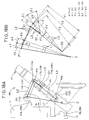
- Fig. 9 is a view of a small-sized tiller, showing the fitting position of the resistance bar 93 according to a first modification.
- the resistance bar 93 extends downwardly from the rear of the power transmission mechanism 12. Specifically, the arm 91 is bolted to the rear lower portions of the right and left brackets 33R and 33L, and the resistance bar 93 is fitted to the arm 91 via the holding portion 92.
- the resistance bar 93 is inserted into ground and restrains the swing of the engine 11 and the power transmission mechanism 12.
- Fig. 10 shows a second modification relative to the fitting of the resistance bar.
- the resistance bar 93 according to the second modification extends downwardly from the manipulating handle 40, and the front end 64a of the damping member 64 is directly fitted to the engine 11 for upward and downward swinging movement with respect to the engine 11.
- Fig. 11 shows a third modification relative to the fitting of the resistance bar.
- the resistance bar 93 according to the third modification extends downwardly from the rear of the power transmission mechanism 12, and the front end 64a of the damping member 64 is directly fitted to the engine 11 for upward and downward swinging movement with respect to the engine 11.
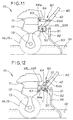
- Fig. 12 shows a fourth modification relative to the fitting of the resistance bar.
- the resistance bar 93 according to the fourth modification extends downwardly from the manipulating handle 40, and the front end 64a of the damping member 64 is directly fitted to the power transmission mechanism 12 for upward and downward swinging movement with respect to the power transmission mechanism 12.
- Fig. 13 shows a fifth modification relative to the fitting of the resistance bar.
- the resistance bar 93 according to the fifth modification extends downwardly from the rear of the power transmission mechanism 12, and the front end 64a of the damping member 64 is directly fitted to the power transmission mechanism 12 for upward and downward swinging movement with respect to the power transmission mechanism 12.
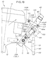
- a suspension 100 according to the second embodiment is a progressive suspension in which the proportion of the stroke of the damping member 64 per predetermined amount of swing varies to a larger extent as the engine 11 and the power transmission mechanism 12 swing about the pivot portion 50 in the direction in which they approach the manipulating handle 40.
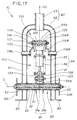
- the suspension 100 has a combined structure of a link mechanism 110 and the damping member 64 as shown in Figs. 15 and 16.
- the link mechanism 110 is made of a bendable link mechanism provided with right and left first links 114R and 114L, right and left second links 115R and 115L, and a connecting bolt 116 which rotatably connect these links.
- the right and left first links 114R and 114L are rotatably fitted to the rear of the engine 11 via a pair of right and left upper brackets 112R and 112L by a connecting bolt 113.
- the upper brackets 112R and 112L are fitted to both right and left sides of a case 17 of the engine 11 by plural bolts 111.
- the front ends of the first links 114R and 114L are rotatably fitted to the rear ends of the upper brackets 112R and 112L by the connecting bolt 113.
- the first links 114R and 114L extend rearwardly.
- the lower ends of the right and left second links 115R and 115L are rotatably fitted to the right and left leg portions 41 and 41 of the handle post part 42 by connecting pins 118R and 118L.
- the rear ends of the first links 114R and 114L and the upper ends of the second links 115R and 115L are rotatably connected by the connecting bolt 116 as described above, and constitute a connection portion 117.
- the front end 64a of the damping member 64 is rotatably connected to the connecting bolt 116 of the connection portion 117.
- the other end 64b of the damping member 64 is rotatably fitted to a pair of right and left plates 91a and 91a by a connecting bolt 123 in such a manner as to be positioned in the upper portion between the plates 91a and 91a which are fixed to the cross pipe 51 of the pivot portion 50 and are spaced apart from each other.
- the two right and left plates 91a and 91a constitute the resistance-bar holding arm 91 which holds the resistance bar 93.
- reference numerals 121, 122 and 122 denote spacers for keeping constant the space between the right and left first links 114R and 114L.
- reference numerals 124 and 124 denote spacers for maintaining the other end 64b of the damping member 64 in the center between the plates 91a and 91a.
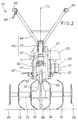
- Figs. 18A and 18B are views showing the principle of the suspension 100 according to the second embodiment.
- points C, P1, Q1, O1 and O2 and lines L1 to L4 are defined as follows:
- the lengths of the lines L1, L2 and L3 are constant.
- the line L3 is the shortest of all the lines L1, L2, L3 and L4, and the lengths of the lines L1, L2, L3 and L4 have the relation of L3 ⁇ L2 ⁇ L4 ⁇ L1.
- the line L3 is nearly superposed on the line L4.
- the lines L1, L2 and L4 are arranged approximately in a triangle.
- the line L1 is further swung by a swing angle ⁇ 2 in the direction of the arrow N.
- the swing angle ⁇ 2 is equal to the swing angle ⁇ 1.
- the point P2 is displaced to the position of the point P3, the point Q2 is displaced to the position of the point Q3 and the line L3 rotates about the point O1 in the clockwise direction by a swing angle ⁇ 2.
- the line L4 rotates about the point O2 in the clockwise direction by a swing angle ⁇ 2.
- the length of the line L4 is Y3 which is shorter than the length Y2. (Y1 - Y2) which is the difference between Y2 and Y3 is represented by ⁇ 2.
- the swing angle of the line L3 becomes larger than the swing angle of the line L1.
- the swing angle of the line L1 is ⁇ 1
- the swing angle of the line L3 is ⁇ 1.
- the swing angle of the line L1 is ⁇ 2 which is equal to the swing angle ⁇ 1
- the swing angle of the line L3 is ⁇ 2 which is larger than ⁇ 1.
- the swing angle ⁇ 1 of the line L4 becomes larger than the swing angle ⁇ 2. Therefore, ⁇ 1 becomes larger than ⁇ 2.
- the proportion of the stroke of the damping member 64 per predetermined amount of swing varies to a great extent.
- the suspension 100 which performs this operation can be regarded as a progressive suspension.
- the damping member 64 becomes shorter by a length equivalent to ⁇ 1 or ⁇ 2.
- shock energy due to the bounding phenomenon acts on the engine 11 and the power transmission mechanism 12 as an upward force.
- the engine 11 and the power transmission mechanism 12 swing upward with respect to the manipulating handle 40, whereby the shock energy is absorbed.
- the shock energy acts on the front end 64a of the damping member 64 from the engine 11 via the upper brackets 112R and 112L, the connecting bolt 113, the first links 114R and 114L and the connecting bolt 116.
- the damping member 64 fully absorbs the shock energy by shrinking rearwardly by a stroke which corresponds to the magnitude of the shock energy.
- the damping member 64 absorbs a small shock energy with a small stroke and a large shock energy with a large stroke. Accordingly, the damping member 64 effectively absorbs the shock energy and facilitates tilling work.
- the stroke of the damping member 64 can be made large by appropriately setting the proportion of the lengths of the second links 115R and 115L to those of the first links 114R and 114L in the link mechanism 110, whereby the shock energy can be absorbed to a further extent by the damping member 64.
- the first links 114R and 114L may be fitted to the power transmission mechanism 12 instead of to the engine 11.
- the resistance bar 93 may be extended downwardly from the rear of the power transmission mechanism 12.
- a small-sized tiller 200 according to the third embodiment is provided with an engine 211 as a power source.
- the driving force outputted from the engine 211 rotates a tilling shaft 213 via a power transmission mechanism 212.
- Plural tilling claws 214 and 215 are fitted to the tilling shaft 213 in the state of being spaced apart from one another at predetermined intervals.
- the small-sized tiller 200 runs while tilling ground by means of the rotation of the tilling claws 214 and 215.
- the small-sized tiller 200 has a manipulating handle 230 which is fitted to the rear of the power transmission mechanism 212 via a pivot 220.
- This manipulating handle 230 extends upwardly rearwardly from the power transmission mechanism 212.
- a resistance bar 237 is fitted to the manipulating handle 230 in such a manner as to extend downwardly from the lower portion of the manipulating handle 230.
- the power transmission mechanism 212 is a mechanism which transmits the driving force of the engine 211 to the tilling shaft 213, and has plural gears (not shown) which are built in a case 216.
- the resistance bar 237 is inserted into the ground Gr to set the tilling depth H for the first and second tilling claws 214 and 215, and produces resistance forces against the advancing forces of the tilling claws 214 and 215.
- reference numeral 217 denotes a cover for blocking the splashing of mud or the like, reference numeral 218 a vehicle-body guard, reference numeral 233 a grip, and reference numeral 234 a clutch lever.
- the engine 211 is disposed along the vehicle-body center line CL.
- the power transmission mechanism 212 is fitted to the lower portion of the engine 211.
- the tilling shaft 213 is fitted to the lower portion of the power transmission mechanism 212 in such a manner as to extend in the width direction of the tiller 200.
- the plural tilling claws 214 and 215 include the first tilling claws 214 and 214 which are respectively disposed at inward positions adjacent to the vehicle-body center line CL, and the second tilling claws 215 and 215 which are respectively disposed at positions outward of the first tilling claws 214 and 214.
- the plural tilling claws 214 and 215 are fitted to the tilling shaft 213 in such a manner as to be arranged at an equal interval in the longitudinal direction of the tilling shaft 213.
- the manipulating handle 230 is made of a handle post part 231 which is fitted to the rear of the power transmission mechanism 212 along the vehicle-body center line CL, and a handle part 43 of approximately U-like shape which is fixed to the top end of the handle post part 231.
- reference numerals 219 and 219 denote side disks.
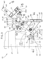
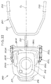
- a pair of right and left damping members 253R and 253L are provided between the power transmission mechanism 212 and the manipulating handle 230. These damping members 253R and 253L reduce shock which occurs due to the rightward or leftward rotation of the power transmission mechanism 212 about the pivot 220 (refer to Fig. 20) when the right or left tilling claw 214 or 215 strikes on a stone or the like buried in ground.
- a pair of right and left arms 241R and 241L extend from the manipulating handle 230 to the right and left sides of the power transmission mechanism 212, respectively.
- a pair of right and left L-shaped links 251R and 251L are rotatably connected to the end portions of the respective right and left arms 241R and 241L.
- Each of the right and left arms 241R and 241L has an approximately U-like shape which is opened toward the front. Since the right damping member 253R and the right L-shaped link 251R are the same in construction as the left damping member 253L and the left L-shaped link 251L, only one of the right- and left-side constructions will be described below as shown in detail in Fig. 23.
- the left arm 241L has a first arm portion 242 extending leftwardly from the manipulating handle 230 shown in Fig. 22.
- the first arm portion 242 has a second arm portion 243 which is bent from the left end of the first arm portion 242 and extends toward the front.
- the corner portion of the L-shaped link 251L is rotatably connected to an arm end portion 244 which is the end portion of the second arm portion 243.
- a bracket 245 which extends upwardly from the corner portion between the first arm portion 242 and the second arm portion 243 is fitted to the left arm 241L.
- One end of the L-shaped link 251L is rotatably fitted to the power transmission mechanism 212 by a pin 257 via a link bracket 56L.
- the other end of the L-shaped link 251L is rotatably connected by a pin 254 to the point of a rod 262a of an oil damper 262 provided with a coil spring 261 which constitutes the damping member 253L.
- the proximal end of the oil damper 262 is rotatably connected to the bracket 245 by a pin 255.
- the coil spring 261 at all times urges the L-shaped link 251L to rotate about a pin 252 in the counterclockwise direction.
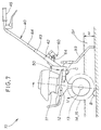
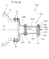
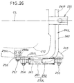
- connection structure among the power transmission mechanism 212, the pivot 220 and the manipulating handle 230 will be described below with reference to Figs. 24 and 25.
- the pivot 220 is provided between the manipulating handle 230 and the power transmission mechanism 212 in such a manner as to extend toward the front and the rear of the small-sized tiller 200 along the vehicle-body center line CL. Accordingly, the power transmission mechanism 212 makes a rightward or leftward rotation (i.e., swings rightwardly or leftwardly) about the pivot 220 with respect to the manipulating handle 230.
- the pivot 220 is made of a horizontal pivot shaft 221 which extends rearwardly from the rear of the power transmission mechanism 212 and a pivot pipe 222 in which the pivot shaft 221 is rotatably fitted.
- the pivot pipe 222 is fixed to the lower portion of the forked portion of the handle post part 231.
- a pair of right and left brackets 223 and 223 are fixed in such a manner to be spaced apart from each other and extend rearwardly from the rear of the power transmission mechanism 212.
- a pivot shaft fitting member 224 to which the pivot shaft 221 is fitted is fixed between this one pair of brackets 223 and 223 by fitting pins 225 and 225 on the right and left sides.
- the pivot shaft 221 has a large-diameter flange portion 221a at its front end, and is engaged with the pivot shaft fitting member 224 at the large-diameter flange portion 221a.
- the pivot shaft 221 has a bolt portion 221b at its rear end, and a washer 227 having approximately the same diameter as the pivot pipe 222 is fitted to the bolt portion 221b by a nut 226.
- the washer 227 prevents the pivot shaft 221 from coming off the pivot pipe 222.
- the pivot 220 has the above-described construction, and the engine 211 and the power transmission mechanism 212 are capable of rotating about the pivot 220 rightwardly or leftwardly with respect to the manipulating handle 230.
- a link bracket 256L draws an upward or downward straight line as viewed in Fig. 25, whereas the locus of swing of the left L-shaped link 251L about the pin 252 draws an arc.
- a pin hole 256a is formed in the link bracket 256L in the shape of a horizontally long slot so that the L-shaped link 251L can make a smooth rotation.
- a vertically extending pipe-shaped holding portion 236 is fitted to the lower rear end of the handle post part 231 along the vehicle-body center line CL.
- the resistance bar 237 is fitted in the holding portion 236.
- the resistance bar 237 is secured to the holding portion 236 by plural securing bolts 38.
- the link bracket 256L fitted to the power transmission mechanism 212 inclines in the rotating direction with respect to the left L-shaped link 251L.
- the left L-shaped link 251L and the link bracket 256L are connected to each other by the pin 257 via an aligning member 258 such as a self-aligning ball bearing.
- connection structure among the left arm 241L, the L-shaped link 251L, the damping member 253L and the link bracket 256L has been described above with reference to Figs. 23 to 26, but since the connection structure among the right arm 241R, the L-shaped link 251R, the damping member 253R and the link bracket 256R has a similar construction, the description of the same construction is omitted.
- the operator grips the manipulating handle 230 and starts walking while steering the small-sized tiller 200.
- the tiller 200 advances and tills ground while rotating the first and second tilling claws 214 and 215 by means of the power transmission mechanism 212 and the tilling shaft 213 by the driving force of the engine 211.
- the operator can insert the resistance bar 237 integral with the manipulating handle 230 into the ground Gr by applying a downward manipulating force to the manipulating handle 230.
- the resistance bar 237 which is inserted in the ground Gr has a resistance force in a direction perpendicular to the axis of the resistance bar 237. Owing to this resistance force, the manipulating handle 230 and the resistance bar 237 exhibit stability in the forward, rearward, rightward and leftward directions of the small-sized tiller 200.
- the manipulating force required to force the manipulating handle 230 forwardly is nearly constant.
- the resistance bar 237 sets the tilling depth H for the first and second tilling claws 214 and 215, and applies resistance forces against the tractive forces of the first and second tilling claws 214 and 215 to the small-sized tiller small-sized tiller 200.
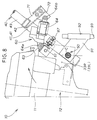
- Fig. 27 is a view showing the state in which during tilling work, the right second tilling claw 215 strikes on the solid object B such as a stone buried in ground and the engine 211 and the power transmission mechanism 212 is rotated about the pivot 220 and inclined in the counterclockwise direction with respect to the manipulating handle 230.
- a bounding phenomenon also called a dashing phenomenon
- Shock energy which serves as the tilling reaction force at this time conducts to the engine 211 and the power transmission mechanism 212 from the right second tilling claw 215 via the tilling shaft 213.
- the resistance bar 237 which extends downwardly from the manipulating handle 230 is inserted in the ground Gr, the resistance bar 237 has a resistance force against the bounding phenomenon. Accordingly, the manipulating handle 230 and the resistance bar 237 are unsusceptible to the influence of the bounding phenomenon.
- the engine 211 and the power transmission mechanism 212 swing about the pivot 220 in the counterclockwise direction with respect to the manipulating handle 230 owing to the shock energy.
- the handle center line HL of the manipulating handle 230 extends nearly vertically
- the vehicle-body center line CL inclines leftwardly so that the shock energy can be absorbed.
- the manipulating handle 230 does not bound nor incline, the steering performance of the small-sized tiller 200 is stable.
- the amount of tilling by the left first and second tilling claws 214 and 215 differs from the amount of tilling by the right first and second tilling claws 214 and 215, so that the right and left tilling reaction forces differ from each other.
- the resistance bar 237 which extends downwardly from the manipulating handle 230 is inserted in the ground Gr, the resistance bar 237 is in a stable state and the manipulating handle 230 is stable. Since the engine 211 and the power transmission mechanism 212 rotate (swing) about the pivot 220 rightwardly or leftwardly with respect to the manipulating handle 230 owing to the right and left different tilling reaction forces, it is possible to absorb the right and left different tilling reaction forces.
- the manipulating handle 230 Since the manipulating handle 230 is stable without bounding or inclining, the operator can maintain the rectilinear running of the small-sized tiller 200 by steering the small-sized tiller 200 while retaining the balance between the right and left portions of the small-sized tiller 200.
- the vehicle-body center line CL inclines toward the right.
- the left link bracket 256L shown in (a) of Fig. 28 is moved up and the left L-shaped link 251L is rotated about the pin 252 in the clockwise direction, whereby the rod 262a of the left damping member 253L is retracted.
- shock energy is absorbed by the damping member 253L.
- the right link bracket 256R shown in (b) of Fig. 28 is moved up and the right L-shaped link 251R is rotated about the pin 252 in the counterclockwise direction, whereby the rod 262a of the right damping member 253R is projected.
- the small-sized tiller 200 converts the right or left rotating (swinging) motion of the engine 211 and the power transmission mechanism 212 into a forward or rearward rotating motion through the pair of right and left L-shaped links 251R and 251L, and transmits the forward or rearward rotating motion to the pair of right and left damping members 253R and 253L.
- the small-sized tiller 200 according to the third embodiment converts the direction of rotating (swinging) motion through the right and left L-shaped links 251R and 251L.
- the tiller according to the third embodiment makes it possible to freely set the projecting/retracting strokes and arrangements of the respective rods 262a of the damping members 253R and 253L, thereby increasing the degree of freedom of design.
- the small-sized tiller 200 provided with the right and left damping members 253R and 253L can be made far more compact.
- the small-sized tiller 200 needs only to have a construction which enables the portion forward of the pivot 220 to swing toward the right and the left 220 with respect to the manipulating handle 230 as viewed from the operator.
- the manipulating handle 230 may be fitted to the rear of the engine 211 via the pivot 220.
- the pivot 220 may also have a construction in which a pivot shaft 221 provided on the handle post part 231 is rotatably fitted in a pivot pipe 222 provided on the rear of the engine 211 or the power transmission mechanism 212.
- the small-sized tiller 200 may have the following construction: the pair of right and left arms 241R and 241L are respectively extended from the manipulating handle 230 to the right and left sides of the engine 211, and the right and left sides of the engine 211 are respectively connected to the ends of the pair of right and left arms 241R and 241L by the pair of right and left L-shaped links 251R and 251L, and the pair of right and left damping members 253R and 253L are respectively interposed between the manipulating handle 230 and the pair of right and left L-shaped links 251R and 251L so that the rightward or leftward swinging motion of the power source 211 can be converted into a forward or rearward swinging motion through the pair of right and left L-shaped links 251R and 251L.
- each of the first, second and third embodiments has referred to an engine as the power source 11, the present invention is not limited to only an engine, and may also use an electric motor.
- a small-sized tiller (10) is provided with a manipulating handle (40) which is swingably fitted via a pivot (50) to the rear of an engine (11) or the rear of a power transmission mechanism (12).
- a manipulating handle (40) which is swingably fitted via a pivot (50) to the rear of an engine (11) or the rear of a power transmission mechanism (12).
- a solid object (B) such as a stone buried in ground
- shock conducts to the engine and the power transmission mechanism via a tilling shaft (13).
- the engine and the power transmission mechanism rotate about the pivot in the upward direction with respect to the manipulating handle. Accordingly, the shock is absorbed by the rotation of the engine and the power transmission mechanism, whereby the manipulating handle becomes stable.
Landscapes
- Life Sciences & Earth Sciences (AREA)
- Engineering & Computer Science (AREA)
- Mechanical Engineering (AREA)
- Soil Sciences (AREA)
- Environmental Sciences (AREA)
- Soil Working Implements (AREA)
Applications Claiming Priority (6)
| Application Number | Priority Date | Filing Date | Title |
|---|---|---|---|
| JP22580199 | 1999-08-09 | ||
| JP22580199 | 1999-08-09 | ||
| JP2000038608A JP3917791B2 (ja) | 1999-08-09 | 2000-02-16 | 小型管理機 |
| JP2000038608 | 2000-02-16 | ||
| JP2000073729A JP3730078B2 (ja) | 2000-03-16 | 2000-03-16 | 小型管理機 |
| JP2000073729 | 2000-03-16 |
Publications (2)
| Publication Number | Publication Date |
|---|---|
| EP1075785A1 true EP1075785A1 (fr) | 2001-02-14 |
| EP1075785B1 EP1075785B1 (fr) | 2003-05-07 |
Family
ID=27331097
Family Applications (1)
| Application Number | Title | Priority Date | Filing Date |
|---|---|---|---|
| EP00117111A Expired - Lifetime EP1075785B1 (fr) | 1999-08-09 | 2000-08-09 | Cultivateur de taille réduite |
Country Status (7)
| Country | Link |
|---|---|
| US (1) | US6540031B1 (fr) |
| EP (1) | EP1075785B1 (fr) |
| KR (1) | KR100614054B1 (fr) |
| CN (1) | CN1135914C (fr) |
| DE (1) | DE60002531T2 (fr) |
| ES (1) | ES2198248T3 (fr) |
| TW (1) | TW480148B (fr) |
Cited By (4)
| Publication number | Priority date | Publication date | Assignee | Title |
|---|---|---|---|---|
| WO2004086850A1 (fr) * | 2003-03-31 | 2004-10-14 | Sunbeam Corporation Limited | Ensemble pour reduire la transmission des vibrations a l'operateur d'une tondeuse |
| EP2018798A3 (fr) * | 2007-07-24 | 2009-03-11 | Yanmar Co., Ltd. | Machine de culture électrique guidée à la main |
| CN102405696A (zh) * | 2010-07-30 | 2012-04-11 | 本田技研工业株式会社 | 耕耘机 |
| IT202000013969A1 (it) * | 2020-06-12 | 2021-12-12 | Francesco Marte | Motozappatrice con asta ripuntatrice a due elementi per il controllo della profondita' di lavoro e velocita' di avanzamento |
Families Citing this family (14)
| Publication number | Priority date | Publication date | Assignee | Title |
|---|---|---|---|---|
| JP3839371B2 (ja) * | 2002-07-11 | 2006-11-01 | 本田技研工業株式会社 | 歩行型作業機 |
| US7270100B2 (en) * | 2005-03-03 | 2007-09-18 | Ardisam, Inc. | Electric start mini-cultivator |
| USD567822S1 (en) * | 2006-12-07 | 2008-04-29 | Pubert Henri Sas | Rotary cultivator |
| US8627897B2 (en) | 2008-09-03 | 2014-01-14 | Black & Decker Inc. | Tiller housing |
| US7963344B2 (en) | 2008-09-03 | 2011-06-21 | Black & Decker Inc. | Tiller with removable battery |
| US8066081B2 (en) * | 2008-11-26 | 2011-11-29 | Honda Motor Co., Ltd. | Small-sized tiller |
| FR2960382B1 (fr) * | 2010-06-01 | 2012-07-20 | Pubert Henri Sas | Equipement a roue de transport escamotable |
| US8499848B2 (en) | 2011-08-05 | 2013-08-06 | Techtronic Outdoor Products Technology Limited | Gas tiller |
| EP2966955A4 (fr) * | 2013-03-14 | 2016-11-23 | Husqvarna Ab | Isolation de vibration à double fonction et pivot de poignée |
| US9167737B2 (en) | 2013-05-22 | 2015-10-27 | Carts & Tools Technology, Inc. | Garden implement |
| JP1652285S (fr) * | 2019-06-12 | 2020-02-03 | ||
| US12439846B2 (en) | 2021-04-19 | 2025-10-14 | Milwaukee Electric Tool Corporation | String trimmer head |
| WO2023278747A1 (fr) | 2021-06-30 | 2023-01-05 | Milwaukee Electric Tool Corporation | Ensemble débroussailleuse et tête de coupe à utiliser avec celle-ci |
| US12582029B2 (en) | 2021-06-30 | 2026-03-24 | Milwaukee Electric Tool Corporation | String trimmer head |
Citations (6)
| Publication number | Priority date | Publication date | Assignee | Title |
|---|---|---|---|---|
| US2375137A (en) * | 1942-04-27 | 1945-05-01 | Rapid Motormaher A G | Motor-carrying ground miller devoid of driving wheel means |
| US2827842A (en) * | 1954-05-05 | 1958-03-25 | Fmc Corp | Agricultural machine |
| US4402366A (en) * | 1980-08-15 | 1983-09-06 | Roper Corporation | Soil tilling machine |
| DE3503938A1 (de) * | 1985-02-06 | 1986-08-07 | Fraunhofer-Gesellschaft zur Förderung der angewandten Forschung e.V., 8000 München | Elastische griffholmen-lagerung fuer beidhaendig gefuehrte motorgeraete |
| EP0262425A2 (fr) * | 1986-09-02 | 1988-04-06 | Hako-Werke GMBH & Co. | Machine automotrice pour le travail du sol menée par un conducteur marchant |
| EP0446681A1 (fr) * | 1990-03-13 | 1991-09-18 | Fraunhofer-Gesellschaft Zur Förderung Der Angewandten Forschung E.V. | Dispositif amortisseur de vibrations pour oscillations verticales |
Family Cites Families (15)
| Publication number | Priority date | Publication date | Assignee | Title |
|---|---|---|---|---|
| US4015407A (en) * | 1975-10-08 | 1977-04-05 | Fmc Corporation | Mower with shock mounts |
| US4396067A (en) * | 1978-06-19 | 1983-08-02 | Gilson Brothers Company | Tiller with rotatable tines and guiding handle |
| US4224996A (en) * | 1978-12-07 | 1980-09-30 | Deere & Company | Control mechanism for a walk-behind rotary tiller |
| US4286670A (en) * | 1978-12-07 | 1981-09-01 | Garden Way Incorporated | Combination tiller and cultivator and drive control therefor |
| US4256183A (en) * | 1979-03-08 | 1981-03-17 | Hanley Martin G | Dual end rotary tiller blade |
| JPS5786502A (en) | 1980-11-17 | 1982-05-29 | Isao Iizuka | Prime mover |
| JPS5786502U (fr) * | 1980-11-19 | 1982-05-28 | ||
| US4392538A (en) * | 1981-01-29 | 1983-07-12 | Roper Corporation | Adjustable handle assembly for walk-behind garden implement |
| US4867244A (en) * | 1987-11-16 | 1989-09-19 | Outboard Marine Corporation | Turf aerating apparatus |
| US4926947A (en) * | 1987-11-16 | 1990-05-22 | Cozine Mark L | Turf aerating apparatus with resilient handle mount |
| US5398767A (en) * | 1988-06-22 | 1995-03-21 | Warke; William L. | Ground treatment apparatus |
| US5197551A (en) * | 1991-09-16 | 1993-03-30 | Farley John L | Extended drag tool for a front tine tiller |
| US5516126A (en) * | 1995-03-10 | 1996-05-14 | Myers; Jeff D. | Snow ski or runner |
| JPH08322302A (ja) * | 1995-05-29 | 1996-12-10 | Shigeki Sano | ロータリー式耕耘機における耕耘部停止装置 |
| US5713420A (en) * | 1995-08-28 | 1998-02-03 | Garden Way, Incorporated | Convertible garden tiller |
-
2000
- 2000-08-07 US US09/633,904 patent/US6540031B1/en not_active Expired - Fee Related
- 2000-08-08 TW TW089115950A patent/TW480148B/zh not_active IP Right Cessation
- 2000-08-09 DE DE60002531T patent/DE60002531T2/de not_active Expired - Lifetime
- 2000-08-09 CN CNB001189905A patent/CN1135914C/zh not_active Expired - Fee Related
- 2000-08-09 ES ES00117111T patent/ES2198248T3/es not_active Expired - Lifetime
- 2000-08-09 KR KR1020000046127A patent/KR100614054B1/ko not_active Expired - Fee Related
- 2000-08-09 EP EP00117111A patent/EP1075785B1/fr not_active Expired - Lifetime
Patent Citations (6)
| Publication number | Priority date | Publication date | Assignee | Title |
|---|---|---|---|---|
| US2375137A (en) * | 1942-04-27 | 1945-05-01 | Rapid Motormaher A G | Motor-carrying ground miller devoid of driving wheel means |
| US2827842A (en) * | 1954-05-05 | 1958-03-25 | Fmc Corp | Agricultural machine |
| US4402366A (en) * | 1980-08-15 | 1983-09-06 | Roper Corporation | Soil tilling machine |
| DE3503938A1 (de) * | 1985-02-06 | 1986-08-07 | Fraunhofer-Gesellschaft zur Förderung der angewandten Forschung e.V., 8000 München | Elastische griffholmen-lagerung fuer beidhaendig gefuehrte motorgeraete |
| EP0262425A2 (fr) * | 1986-09-02 | 1988-04-06 | Hako-Werke GMBH & Co. | Machine automotrice pour le travail du sol menée par un conducteur marchant |
| EP0446681A1 (fr) * | 1990-03-13 | 1991-09-18 | Fraunhofer-Gesellschaft Zur Förderung Der Angewandten Forschung E.V. | Dispositif amortisseur de vibrations pour oscillations verticales |
Cited By (7)
| Publication number | Priority date | Publication date | Assignee | Title |
|---|---|---|---|---|
| WO2004086850A1 (fr) * | 2003-03-31 | 2004-10-14 | Sunbeam Corporation Limited | Ensemble pour reduire la transmission des vibrations a l'operateur d'une tondeuse |
| EP1613143A4 (fr) * | 2003-03-31 | 2008-02-13 | Victa Lawncare Pty Ltd | Ensemble pour reduire la transmission des vibrations a l'operateur d'une tondeuse |
| AU2004226873B2 (en) * | 2003-03-31 | 2010-01-07 | Victa Lawncare Pty. Ltd. | Assembly to reduce the transmission of vibration to the operator of a lawn mower |
| EP2018798A3 (fr) * | 2007-07-24 | 2009-03-11 | Yanmar Co., Ltd. | Machine de culture électrique guidée à la main |
| CN102405696A (zh) * | 2010-07-30 | 2012-04-11 | 本田技研工业株式会社 | 耕耘机 |
| CN102405696B (zh) * | 2010-07-30 | 2014-04-23 | 本田技研工业株式会社 | 耕耘机 |
| IT202000013969A1 (it) * | 2020-06-12 | 2021-12-12 | Francesco Marte | Motozappatrice con asta ripuntatrice a due elementi per il controllo della profondita' di lavoro e velocita' di avanzamento |
Also Published As
| Publication number | Publication date |
|---|---|
| KR20010050027A (ko) | 2001-06-15 |
| CN1283381A (zh) | 2001-02-14 |
| CN1135914C (zh) | 2004-01-28 |
| ES2198248T3 (es) | 2004-02-01 |
| DE60002531D1 (de) | 2003-06-12 |
| US6540031B1 (en) | 2003-04-01 |
| KR100614054B1 (ko) | 2006-08-22 |
| EP1075785B1 (fr) | 2003-05-07 |
| TW480148B (en) | 2002-03-21 |
| DE60002531T2 (de) | 2004-04-01 |
Similar Documents
| Publication | Publication Date | Title |
|---|---|---|
| EP1075785B1 (fr) | Cultivateur de taille réduite | |
| EP2061693B1 (fr) | Suspension de bicyclette | |
| SE519318C2 (sv) | Framhjulsupphängning för företrädesvis motorcykel | |
| DE102005044837B4 (de) | Motorrad | |
| JP4896098B2 (ja) | 農作業機 | |
| JP3896748B2 (ja) | フロントロータリ耕耘装置 | |
| JP3917791B2 (ja) | 小型管理機 | |
| JP4339021B2 (ja) | スイングアーム式懸架装置 | |
| JP2001128507A (ja) | 田植機の線引きマーカ | |
| JP4484787B2 (ja) | 乗用型田植機 | |
| JP3730078B2 (ja) | 小型管理機 | |
| JP2004215602A (ja) | 歩行型農作業機 | |
| RU74365U1 (ru) | Велосипед | |
| JPH0631015B2 (ja) | 乗用水田作業車 | |
| JP3930659B2 (ja) | 田植機の植付フレーム | |
| JPH0330233Y2 (fr) | ||
| JP3076937B2 (ja) | 歩行田植機の機体構造 | |
| JP4382677B2 (ja) | 作業車 | |
| JPS5837203Y2 (ja) | ロ−タリ作業機 | |
| JPH0143988Y2 (fr) | ||
| JPH0646258Y2 (ja) | 草刈機の基台構造 | |
| JPH10297529A5 (fr) | ||
| JP2527550Y2 (ja) | 自動二輪車の後ホーク | |
| JPS6048123B2 (ja) | 田植機 | |
| JP2003153618A (ja) | 田植機 |
Legal Events
| Date | Code | Title | Description |
|---|---|---|---|
| PUAI | Public reference made under article 153(3) epc to a published international application that has entered the european phase |
Free format text: ORIGINAL CODE: 0009012 |
|
| AK | Designated contracting states |
Kind code of ref document: A1 Designated state(s): DE ES FR GB IT |
|
| AX | Request for extension of the european patent |
Free format text: AL;LT;LV;MK;RO;SI |
|
| 17P | Request for examination filed |
Effective date: 20010202 |
|
| 17Q | First examination report despatched |
Effective date: 20010518 |
|
| AKX | Designation fees paid |
Free format text: DE ES FR GB IT |
|
| GRAH | Despatch of communication of intention to grant a patent |
Free format text: ORIGINAL CODE: EPIDOS IGRA |
|
| GRAH | Despatch of communication of intention to grant a patent |
Free format text: ORIGINAL CODE: EPIDOS IGRA |
|
| GRAA | (expected) grant |
Free format text: ORIGINAL CODE: 0009210 |
|
| AK | Designated contracting states |
Designated state(s): DE ES FR GB IT |
|
| REG | Reference to a national code |
Ref country code: GB Ref legal event code: FG4D |
|
| REF | Corresponds to: |
Ref document number: 60002531 Country of ref document: DE Date of ref document: 20030612 Kind code of ref document: P |
|
| ET | Fr: translation filed | ||
| REG | Reference to a national code |
Ref country code: ES Ref legal event code: FG2A Ref document number: 2198248 Country of ref document: ES Kind code of ref document: T3 |
|
| PLBE | No opposition filed within time limit |
Free format text: ORIGINAL CODE: 0009261 |
|
| STAA | Information on the status of an ep patent application or granted ep patent |
Free format text: STATUS: NO OPPOSITION FILED WITHIN TIME LIMIT |
|
| 26N | No opposition filed |
Effective date: 20040210 |
|
| PGFP | Annual fee paid to national office [announced via postgrant information from national office to epo] |
Ref country code: ES Payment date: 20130711 Year of fee payment: 14 Ref country code: DE Payment date: 20130807 Year of fee payment: 14 |
|
| PGFP | Annual fee paid to national office [announced via postgrant information from national office to epo] |
Ref country code: GB Payment date: 20130807 Year of fee payment: 14 Ref country code: FR Payment date: 20130808 Year of fee payment: 14 |
|
| PGFP | Annual fee paid to national office [announced via postgrant information from national office to epo] |
Ref country code: IT Payment date: 20130821 Year of fee payment: 14 |
|
| REG | Reference to a national code |
Ref country code: DE Ref legal event code: R119 Ref document number: 60002531 Country of ref document: DE |
|
| GBPC | Gb: european patent ceased through non-payment of renewal fee |
Effective date: 20140809 |
|
| PG25 | Lapsed in a contracting state [announced via postgrant information from national office to epo] |
Ref country code: IT Free format text: LAPSE BECAUSE OF NON-PAYMENT OF DUE FEES Effective date: 20140809 |
|
| REG | Reference to a national code |
Ref country code: DE Ref legal event code: R119 Ref document number: 60002531 Country of ref document: DE Effective date: 20150303 |
|
| REG | Reference to a national code |
Ref country code: FR Ref legal event code: ST Effective date: 20150430 |
|
| PG25 | Lapsed in a contracting state [announced via postgrant information from national office to epo] |
Ref country code: DE Free format text: LAPSE BECAUSE OF NON-PAYMENT OF DUE FEES Effective date: 20150303 Ref country code: GB Free format text: LAPSE BECAUSE OF NON-PAYMENT OF DUE FEES Effective date: 20140809 |
|
| PG25 | Lapsed in a contracting state [announced via postgrant information from national office to epo] |
Ref country code: FR Free format text: LAPSE BECAUSE OF NON-PAYMENT OF DUE FEES Effective date: 20140901 |
|
| REG | Reference to a national code |
Ref country code: ES Ref legal event code: FD2A Effective date: 20150925 |
|
| PG25 | Lapsed in a contracting state [announced via postgrant information from national office to epo] |
Ref country code: ES Free format text: LAPSE BECAUSE OF NON-PAYMENT OF DUE FEES Effective date: 20140810 |