EP1075902A2 - Pince de traitement mécanique de pièces - Google Patents
Pince de traitement mécanique de pièces Download PDFInfo
- Publication number
- EP1075902A2 EP1075902A2 EP00115204A EP00115204A EP1075902A2 EP 1075902 A2 EP1075902 A2 EP 1075902A2 EP 00115204 A EP00115204 A EP 00115204A EP 00115204 A EP00115204 A EP 00115204A EP 1075902 A2 EP1075902 A2 EP 1075902A2
- Authority
- EP
- European Patent Office
- Prior art keywords
- pliers
- spacer
- working
- plunger
- drive
- Prior art date
- Legal status (The legal status is an assumption and is not a legal conclusion. Google has not performed a legal analysis and makes no representation as to the accuracy of the status listed.)
- Withdrawn
Links
Images


Classifications
-
- B—PERFORMING OPERATIONS; TRANSPORTING
- B25—HAND TOOLS; PORTABLE POWER-DRIVEN TOOLS; MANIPULATORS
- B25B—TOOLS OR BENCH DEVICES NOT OTHERWISE PROVIDED FOR, FOR FASTENING, CONNECTING, DISENGAGING, OR HOLDING
- B25B7/00—Pliers; Other hand-held gripping tools with jaws on pivoted limbs; Details applicable generally to pivoted-limb hand tools
- B25B7/12—Pliers; Other hand-held gripping tools with jaws on pivoted limbs; Details applicable generally to pivoted-limb hand tools involving special transmission means between the handles and the jaws, e.g. toggle levers, gears
- B25B7/126—Pliers; Other hand-held gripping tools with jaws on pivoted limbs; Details applicable generally to pivoted-limb hand tools involving special transmission means between the handles and the jaws, e.g. toggle levers, gears with fluid drive
-
- B—PERFORMING OPERATIONS; TRANSPORTING
- B23—MACHINE TOOLS; METAL-WORKING NOT OTHERWISE PROVIDED FOR
- B23D—PLANING; SLOTTING; SHEARING; BROACHING; SAWING; FILING; SCRAPING; LIKE OPERATIONS FOR WORKING METAL BY REMOVING MATERIAL, NOT OTHERWISE PROVIDED FOR
- B23D29/00—Hand-held metal-shearing or metal-cutting devices
- B23D29/02—Hand-operated metal-shearing devices
Definitions
- the invention relates to pliers for the mechanical processing of workpieces according to the preamble of claim 1.
- GB 20 74 487 A is a pair of pliers for opening a flange connection with two Pliers member known, which is formed by rotatably mounted levers become.
- the plunger of a drive piston engages a pliers link while the other pliers member is rigidly attached to the drive piston.
- a Actuating lever By means of a Actuating lever, a working stroke can be triggered through which the first tong member is movable against the fixed pliers link.
- EP 0 299 477 A1 is a hydraulically operated hand-held device, such as pliers or Scissors, for cutting and / or shaping objects from high-strength Material with a hydraulic system with a downstream pressure medium working cylinder known in which a pressure piston moving the tool can be displaced, and wherein the pressure medium by means of a hand lever coupled to a control piston is pumped into the working cylinder.
- the pressure piston then moves outside and presses the two pliers levers with their scissor surfaces or the like against each other. By pressing the scissor surfaces together or the like, the created workpiece, e.g. a bolt, a pipe, cut or deformed.
- Pliers according to the preamble of claim 1 which as a mobile tool can be guided manually to a component for many years at Sheet metal processing used.
- training as a handheld device carries the risk that an operator's hand or individual fingers between the Working ends of the pliers links reach an open pliers and there be squeezed off in a subsequent working stroke.
- a pneumatically operated hand tool in which a pliers mouth formed by movable jaws is characterized by that the forceps mouth in its open position by a movable one in it accommodated displacement body, for example a leaf spring, closed to prevent the inadvertent entry of foreign bodies.
- a movable one in it accommodated displacement body for example a leaf spring
- the object of the invention is therefore a pair of pliers according to the preamble of To create claim 1, which allows pure one-handed operation.
- Such pliers can only be used with one hand and without anything Reaching are operated. Furthermore, such pliers can be a comparative Large opening dimension between an upper and a lower tool of the pliers offer, from which an expanded range of applications with regard to the machined Workpiece areas follows.
- the free end is coupled to a tension spring, a coupling of the spacer ensured from the power transmission chain. Only when using a die Pulling force of the tension spring overcome is a coupling of the spacer in the power transmission chain.
- the coupling of the spacer can only then be guaranteed be when an operator holds down a one-hand control lever. in the In the event of a slight decrease in the operating force, it can be provided that the Spacer back out of the power transmission chain even during the working stroke is pulled out, whereby the working stroke is interrupted. this means Additional security, because after a work stroke has been triggered an end the work does not necessarily have to take place.
- the actuating element can be operated in the manner of a trigger on the pliers handle be to couple the spacer against the tension spring force.
- a pressure point incorporated into the actuating path of the actuating element be the coupling of the spacer into the power transmission chain between plunger and swiveling pliers link and as an announcement the forthcoming work stroke triggering.
- the invention relates to pliers for mechanical machining of workpieces, especially pliers for shearing, cutting, punching, punching, riveting and Enforcing sheets, tubes and profiles with the example below for a set of pliers.
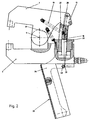
- Figures 1 to 4 show a pair of pliers with a first pliers member 1 and second pliers member 2, each formed as a two-armed pliers legs and are pivotally connected about the axis 4 via a pincer joint 3.
- a plier handle 5 is fixedly attached to the pliers member 2.
- the pliers link 2 is therefore often referred to as the fixed pliers member 2, while the tong member 1 is referred to as the movable tong member 1.
- the pliers links 1, 2 each have a working end 7, 8 on which a tool in a tool nest can be attached and a handle-side rear end.
- stamps and dies are used as tools.
- a Return spring 21 which acts on both pliers members 1, 2, preferably on the lever arms of the two-armed pliers links opposite the working ends 1, 2, the working ends 7, 8 are kept open and can only counter the Restoring force of the spring 21 can be approximated.
- the pliers links 1, 2 also each have a working end 7, 8 opposite Drive end 9, 10, which at the pliers member 1 of the spacer 11th and in the pliers member 2 is formed by an end face of a plunger 27.
- the Spacer 11 is, as can be seen from FIGS. 1 to 3, pivotable on one fixed rear end 13 of the movable pliers member 1. For that has the Spacer 11 lateral tabs 14, 15, which are on both sides at the rear end 13 are fastened by means of a fastening bolt 16 which has a pivot axis 17 Are defined.
- the spacer 11 represents a one-armed lever that one Extension arm of the pliers member 1 forms.
- a tension spring 19 At a free end 18 of the spacer 11 engages a tension spring 19, the other end is attached to the upper pliers member 1.
- the tension force of the tension spring 19 causes the spacer 11 to the pliers member 1 and thus in one Interior of the pliers is pulled.
- the spacer 11 which is shown uncoupled from the power flow in FIG. 1, is of the tension spring 19 outside a Vorhubweges a plunger 27th positioned, the return spring 21, the pliers member 1 together with the Spacer 11 against the lever arm facing away from the working end 8 with a Tappet adjusting screw 12 on the outside pulls until the spacer the set screw 12 of the pliers member 2 hits (the location is marked with 26), so far forms a stop.
- the pliers member 2 has one on the lever arm facing away from the working end 8 Drive piston 20, the plunger 27 in a direction parallel to a tool axis 28 has a preliminary stroke as a working stroke.
- the forward stroke of the drive piston is limited by a lower end of the screw 12 and is by these selectable.
- the application of the drive piston 20 can be pneumatic or take place hydraulically, for which purpose a drive medium connection 29 is provided.
- the Pliers member 2 also has a switch 30. When the button is pressed 31 the forward stroke of the drive piston 20 is triggered. After lifting this Actuating force uses a return stroke of the drive piston 20.
- the pivoting on the pliers handle 5 actuating element 24 provided.
- the actuating element 24 is at the handle end of the pliers handle 5 pivoted about the axis 32.
- the actuating element 24 is formed by a pincer grip 33 which acts as a one-sided lever at the pincer end is pivotally mounted and has at least one actuating arm 34, 35 which directly or via at least one driver element attached to the spacer 11 22, 23 is brought into engagement in such a way that the one acting on the spacer 11 Tension spring 19 the pliers handle shell 33 spring biased relative to the pliers handle 5 angled.
- the one or more actuating arms 34, 35 can be seen laterally on the a pliers member 2 swords passed.
- Such sword-shaped Actuating arms 34, 35 can have an outer contour that is selected in this way is that the drive mechanism surrounding the drive ends of the tong members 1, 2 is not covered manually on the side.
- the spacer 11 is rotatably fixed to the rear End 13 of the pliers member 1, pivoted into the preliminary stroke of the plunger 27, wherein the angle of the pliers grip shell 33 is selected such that its swivel path leads to the complete coupling of the spacer 11.
- the length of the spacer 11 when it is aligned with the pre-stroke direction of the Ram 27 can be chosen such that the working ends 7, 8 up to one 2 only by the action of a hand approach. Such a closed position is present, for example, when the Working ends 7, 8 picked tools have approached to 6 mm.
- the pivoting movement carried out by the spacer 11 is thus accompanied from a pivoting movement of the pliers member 1 on which the spacer 11 is attached and thus realizes the manual closing movement.
- the spacer 11 is set up. So that this combined movement by pressing the Actuating element 24 is possible, the actuating member 24 has at least an actuating arm 37 for the direct or via driver elements 22, 23 mediated actuation of the spacer 11.
- a cam 40 is provided on the actuating element 24, which on Moves end of the closing movement against a switch 30 that the forward stroke of Ram 27 and thus the actual working stroke for, for example, a joining triggers.
- the pliers handle shell 33 can be pressed on the pliers handle 5 just before the actuator 24 against the cam 40 Switch pin 31 moves, an additional pressure force on the actuator 24th applies.
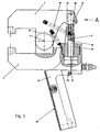
- Fig. 3 shows the pressure joining pliers described above at the end of the working stroke.
- the spacer 11 closes the power transmission chain and the plunger 27 extended to its maximum forward stroke.
- the plunger 27 has one Stroke axis, which can be fastened parallel to the longitudinal axis of a pincer 2 Tool.
Landscapes
- Engineering & Computer Science (AREA)
- Mechanical Engineering (AREA)
- Gripping Jigs, Holding Jigs, And Positioning Jigs (AREA)
- Portable Power Tools In General (AREA)
- Press Drives And Press Lines (AREA)
- Forging (AREA)
Applications Claiming Priority (2)
| Application Number | Priority Date | Filing Date | Title |
|---|---|---|---|
| DE19934288 | 1999-07-21 | ||
| DE19934288A DE19934288C1 (de) | 1999-07-21 | 1999-07-21 | Zange zum mechanischen Bearbeiten von Werkstücken |
Publications (2)
| Publication Number | Publication Date |
|---|---|
| EP1075902A2 true EP1075902A2 (fr) | 2001-02-14 |
| EP1075902A3 EP1075902A3 (fr) | 2003-03-26 |
Family
ID=7915606
Family Applications (1)
| Application Number | Title | Priority Date | Filing Date |
|---|---|---|---|
| EP00115204A Withdrawn EP1075902A3 (fr) | 1999-07-21 | 2000-07-13 | Pince de traitement mécanique de pièces |
Country Status (5)
| Country | Link |
|---|---|
| US (1) | US6427515B1 (fr) |
| EP (1) | EP1075902A3 (fr) |
| JP (1) | JP3713191B2 (fr) |
| DE (1) | DE19934288C1 (fr) |
| NO (1) | NO313542B1 (fr) |
Cited By (2)
| Publication number | Priority date | Publication date | Assignee | Title |
|---|---|---|---|---|
| CN111482869A (zh) * | 2020-04-20 | 2020-08-04 | 马鞍山市德钢模具制造有限公司 | 一种轮毂模具加工用表面处理设备 |
| CN111558788A (zh) * | 2020-04-07 | 2020-08-21 | 河南工学院 | 一种基于激光与光通信领域适用于激光打孔的定位夹紧装置 |
Families Citing this family (5)
| Publication number | Priority date | Publication date | Assignee | Title |
|---|---|---|---|---|
| US7331207B2 (en) * | 2005-03-11 | 2008-02-19 | Hot Metal Customs, Inc. | Metal shaping apparatus |
| USD571382S1 (en) | 2006-03-10 | 2008-06-17 | Hot Metal Customs, Inc. | Metal shaping apparatus |
| DE102009049616B4 (de) * | 2009-10-16 | 2019-05-09 | Böllhoff Verbindungstechnik GmbH | Setzgerät, Zuführmodul des Setzgeräts und Fügeverfahren zum Verbinden von mindestens zwei Bauteilen |
| DE102011052350A1 (de) | 2011-08-02 | 2013-02-07 | Gustav Klauke Gmbh | Backenpaar zum Ausstanzen von Löchern |
| CN102615234B (zh) * | 2012-04-18 | 2014-06-04 | 磐安县丰源工艺品有限公司 | 一种铆钉压紧装置 |
Family Cites Families (9)
| Publication number | Priority date | Publication date | Assignee | Title |
|---|---|---|---|---|
| US3058214A (en) * | 1961-12-12 | 1962-10-16 | Mekler Dan | Hydraulically operatable hand tool |
| DE1952068A1 (de) | 1969-10-16 | 1971-04-29 | Siemens Ag | Erregeranordnung fuer einen buerstenlosen Synchrongenerator |
| US4206603A (en) * | 1977-07-13 | 1980-06-10 | Dan Mekler | Single hand operated tool |
| DE3015602C2 (de) * | 1980-04-23 | 1985-11-14 | Süddeutsche Kühlerfabrik Julius Fr. Behr GmbH & Co KG, 7000 Stuttgart | Vorrichtung zum Öffnen von Bördelverbindungen |
| DE3723330A1 (de) * | 1987-07-15 | 1989-01-26 | Paul Zahn | Hydraulisch betaetigtes handgeraet |
| SE9101225D0 (sv) * | 1991-04-23 | 1991-04-23 | Attexor S A | A method and an apparatus for carrying out an operation on a mechanical workpiece |
| SE505162C2 (sv) * | 1995-03-22 | 1997-07-07 | Pressmaster Tool Ab | Verktygshuvud |
| SE9501251D0 (sv) * | 1995-04-03 | 1995-04-03 | Attexor Equip | Merhod and apparatus for carrying out an operatopn on a mechanical workpiece |
| DE19542068C2 (de) * | 1995-11-11 | 1999-12-02 | Audi Ag | Zangenartiges Werkzeug |
-
1999
- 1999-07-21 DE DE19934288A patent/DE19934288C1/de not_active Expired - Fee Related
-
2000
- 2000-07-13 EP EP00115204A patent/EP1075902A3/fr not_active Withdrawn
- 2000-07-20 NO NO20003733A patent/NO313542B1/no unknown
- 2000-07-21 US US09/620,967 patent/US6427515B1/en not_active Expired - Fee Related
- 2000-07-21 JP JP2000226200A patent/JP3713191B2/ja not_active Expired - Fee Related
Cited By (3)
| Publication number | Priority date | Publication date | Assignee | Title |
|---|---|---|---|---|
| CN111558788A (zh) * | 2020-04-07 | 2020-08-21 | 河南工学院 | 一种基于激光与光通信领域适用于激光打孔的定位夹紧装置 |
| CN111482869A (zh) * | 2020-04-20 | 2020-08-04 | 马鞍山市德钢模具制造有限公司 | 一种轮毂模具加工用表面处理设备 |
| CN111482869B (zh) * | 2020-04-20 | 2022-05-10 | 马鞍山市德钢模具制造有限公司 | 一种轮毂模具加工用表面处理设备 |
Also Published As
| Publication number | Publication date |
|---|---|
| EP1075902A3 (fr) | 2003-03-26 |
| DE19934288C1 (de) | 2000-12-07 |
| NO20003733L (no) | 2001-01-22 |
| NO20003733D0 (no) | 2000-07-20 |
| US6427515B1 (en) | 2002-08-06 |
| JP2001071182A (ja) | 2001-03-21 |
| NO313542B1 (no) | 2002-10-21 |
| JP3713191B2 (ja) | 2005-11-02 |
Similar Documents
| Publication | Publication Date | Title |
|---|---|---|
| DE19737133C2 (de) | Fluidbetätigte Vorrichtung zur Verwendung mit einer Vielzahl von Werkzeugen | |
| EP1979110B1 (fr) | Appareil de sertissage hydraulique et procede de sertissage d'un raccord | |
| DE2166983C3 (de) | Chirurgisches Instrument zum Herumlegen von Klammern zum Abbinden rohrförmiger organischer Gebilde | |
| DE102007001235B4 (de) | Presszange zum Verpressen von Werkstücken | |
| DE10102089C1 (de) | Chirurgisches Instrument | |
| DE3423283C2 (fr) | ||
| EP2142340B1 (fr) | Outil à pince manuel | |
| DE3714156A1 (de) | Von hand betaetigbarer kabeltrenner | |
| EP0860245B1 (fr) | Dispositif de pressage | |
| WO2019122243A1 (fr) | Outil hydraulique pour un dispositif de traction et/ou de pressage | |
| DE10297071B4 (de) | Einhandrohrzange | |
| EP0940203A2 (fr) | Outil de rivetage à main pour rivets aveugles | |
| DE19934288C1 (de) | Zange zum mechanischen Bearbeiten von Werkstücken | |
| DE19621877C2 (de) | Preßzange | |
| DE102008007303B4 (de) | Spreizzange | |
| DE69222531T2 (de) | Selbstverriegelnde handwerkzeuge | |
| DE4420006C2 (de) | Zange zum Abisolieren von Leiterenden | |
| DE3889666T2 (de) | Zange. | |
| EP3542963B1 (fr) | Tenseur | |
| EP2385891B1 (fr) | Pince destinée à l'assemblage par manchon coulissant | |
| DE10024083C1 (de) | Schere zum Durchtrennen eines Verbundrohres | |
| DE10243707B3 (de) | Handzange zum Verpressen von Rohrverbindungen | |
| DE10217266C5 (de) | Preßzange zum Verpressen von Hohlkörpern | |
| EP0058349A2 (fr) | Outil pour déformer, presser ou pour exécuter d'autres opérations sous l'application de pression | |
| DE272839C (fr) |
Legal Events
| Date | Code | Title | Description |
|---|---|---|---|
| PUAI | Public reference made under article 153(3) epc to a published international application that has entered the european phase |
Free format text: ORIGINAL CODE: 0009012 |
|
| AK | Designated contracting states |
Kind code of ref document: A2 Designated state(s): AT BE CH CY DE DK ES FI FR GB GR IE IT LI LU MC NL PT SE |
|
| AX | Request for extension of the european patent |
Free format text: AL;LT;LV;MK;RO;SI |
|
| PUAL | Search report despatched |
Free format text: ORIGINAL CODE: 0009013 |
|
| AK | Designated contracting states |
Kind code of ref document: A3 Designated state(s): AT BE CH CY DE DK ES FI FR GB GR IE IT LI LU MC NL PT SE Designated state(s): AT BE CH CY DE DK ES FI FR GB GR IE IT LI LU MC NL PT SE |
|
| AX | Request for extension of the european patent |
Extension state: AL LT LV MK RO SI |
|
| RIC1 | Information provided on ipc code assigned before grant |
Ipc: 7B 23D 29/02 B Ipc: 7B 25B 7/12 A |
|
| 17P | Request for examination filed |
Effective date: 20030524 |
|
| AKX | Designation fees paid |
Designated state(s): AT BE CH CY DE DK ES FI FR GB GR IE IT LI LU MC NL PT SE |
|
| GRAP | Despatch of communication of intention to grant a patent |
Free format text: ORIGINAL CODE: EPIDOSNIGR1 |
|
| STAA | Information on the status of an ep patent application or granted ep patent |
Free format text: STATUS: THE APPLICATION IS DEEMED TO BE WITHDRAWN |
|
| 18D | Application deemed to be withdrawn |
Effective date: 20080501 |