EP1075980A1 - Capteur de courant pour un véhicule ferroviaire - Google Patents
Capteur de courant pour un véhicule ferroviaire Download PDFInfo
- Publication number
- EP1075980A1 EP1075980A1 EP00117441A EP00117441A EP1075980A1 EP 1075980 A1 EP1075980 A1 EP 1075980A1 EP 00117441 A EP00117441 A EP 00117441A EP 00117441 A EP00117441 A EP 00117441A EP 1075980 A1 EP1075980 A1 EP 1075980A1
- Authority
- EP
- European Patent Office
- Prior art keywords
- pantograph
- roof
- car body
- hydraulic
- rail vehicle
- Prior art date
- Legal status (The legal status is an assumption and is not a legal conclusion. Google has not performed a legal analysis and makes no representation as to the accuracy of the status listed.)
- Withdrawn
Links
Images


Classifications
-
- B—PERFORMING OPERATIONS; TRANSPORTING
- B60—VEHICLES IN GENERAL
- B60L—PROPULSION OF ELECTRICALLY-PROPELLED VEHICLES; SUPPLYING ELECTRIC POWER FOR AUXILIARY EQUIPMENT OF ELECTRICALLY-PROPELLED VEHICLES; ELECTRODYNAMIC BRAKE SYSTEMS FOR VEHICLES IN GENERAL; MAGNETIC SUSPENSION OR LEVITATION FOR VEHICLES; MONITORING OPERATING VARIABLES OF ELECTRICALLY-PROPELLED VEHICLES; ELECTRIC SAFETY DEVICES FOR ELECTRICALLY-PROPELLED VEHICLES
- B60L5/00—Current collectors for power supply lines of electrically-propelled vehicles
- B60L5/18—Current collectors for power supply lines of electrically-propelled vehicles using bow-type collectors in contact with trolley wire
- B60L5/22—Supporting means for the contact bow
- B60L5/28—Devices for lifting and resetting the collector
-
- B—PERFORMING OPERATIONS; TRANSPORTING
- B60—VEHICLES IN GENERAL
- B60L—PROPULSION OF ELECTRICALLY-PROPELLED VEHICLES; SUPPLYING ELECTRIC POWER FOR AUXILIARY EQUIPMENT OF ELECTRICALLY-PROPELLED VEHICLES; ELECTRODYNAMIC BRAKE SYSTEMS FOR VEHICLES IN GENERAL; MAGNETIC SUSPENSION OR LEVITATION FOR VEHICLES; MONITORING OPERATING VARIABLES OF ELECTRICALLY-PROPELLED VEHICLES; ELECTRIC SAFETY DEVICES FOR ELECTRICALLY-PROPELLED VEHICLES
- B60L5/00—Current collectors for power supply lines of electrically-propelled vehicles
- B60L5/18—Current collectors for power supply lines of electrically-propelled vehicles using bow-type collectors in contact with trolley wire
- B60L5/19—Current collectors for power supply lines of electrically-propelled vehicles using bow-type collectors in contact with trolley wire using arrangements for effecting collector movement transverse to the direction of vehicle motion
-
- B—PERFORMING OPERATIONS; TRANSPORTING
- B60—VEHICLES IN GENERAL
- B60L—PROPULSION OF ELECTRICALLY-PROPELLED VEHICLES; SUPPLYING ELECTRIC POWER FOR AUXILIARY EQUIPMENT OF ELECTRICALLY-PROPELLED VEHICLES; ELECTRODYNAMIC BRAKE SYSTEMS FOR VEHICLES IN GENERAL; MAGNETIC SUSPENSION OR LEVITATION FOR VEHICLES; MONITORING OPERATING VARIABLES OF ELECTRICALLY-PROPELLED VEHICLES; ELECTRIC SAFETY DEVICES FOR ELECTRICALLY-PROPELLED VEHICLES
- B60L2200/00—Type of vehicles
- B60L2200/26—Rail vehicles
Definitions
- the invention relates to a rail vehicle with at least a car body, on the roof of which there is at least one pantograph with its support electrically isolated and from the roof of the Car body is spaced apart, at least one Pantographs can be raised into an operating position and into a rest position is lowerable.
- Such rail vehicles have, if they are multi-system vehicles are executed for the different systems at least one pantograph. At least that is some of the pantographs on the roofs of car bodies arranged, which serve as passenger compartments. The same goes for for rail vehicles designed as multiple units, and so that there are no powered heads inaccessible to passengers.
- the clearance profile of the route to be traveled not to hurt and on the other hand at the deepest under part of the pantograph standing under electrical voltage The minimum air gap to the roof of the car body must be observed the roof of the car body in the area of the pantograph opposite the remaining area of the roof is usually lowered.
- the lowering of the roof leads to a reduced interior height.
- the roof height is usually reduced, among others determines the torsional rigidity of the car body.
- the object of the present invention is a rail vehicle of the type mentioned at the outset, on the one hand with regard to the structural design of the car body is not subject to any restrictions and on the other hand that Clearance profile of the routes to be traveled is not violated.
- the rail vehicle according to claim 1 comprises at least one Car body with at least one pantograph on the roof its support electrically insulated and the roof of the car body in front is arranged spaced apart, at least one pantograph can be raised into an operating position and into a rest position is lowerable.
- the carrier of the pantograph is by an adjusting device in its height distance to Roof of the car body so adjustable that in one Rested, lowered and electrically de-energized pantograph the height distance between the lowest under electrical Live part of the pantograph and the roof is less than the minimum air gap by a predeterminable difference value, and that with a raised in operational position and pantographs under voltage the height distance between the lowest under electrical Voltage part of the pantograph and the roof at least corresponds to the minimum air gap.
- the respective Safety distance of the pantograph from the roof of the car body adaptable to the respective operating cases. Is the pantograph lowered to its rest position and electrically de-energized then the height difference between the Carrier of the pantograph and the roof of the car body around a predefinable limit value smaller than the minimum air gap. However, the pantograph is in its operating position raised, then the height distance between the Carrier of the pantograph and the roof of the car body at least the minimum air gap. The pantograph can then safely connected to the electrical voltage (contact wire voltage) become.
- pantograph Since the working height of the pantograph is adjustable the maximum possible body height under the pantograph determined by the resting position of the pantograph. For rail vehicles, where the pantograph against the slope of the car body is traceable, is in addition to the rest position the pantograph still take into account its swivel position.
- the pantograph must counter the inclination of the car body to be led back. In this case it is special advantageous, the rail vehicle according to claim 2 or 3 to train.
- the actuating device can be an electro-mechanical Steep device (claim 4) or as an electro-pneumatic Actuating device (claim 5) formed his.
- the actuator can be used as an electro-hydraulic Actuating device (claim 6) or as an electro-pneumatic-hydraulic Actuating device (claim 7) formed his.
- a pantograph 3rd is arranged with its carrier 4.
- the carrier 4 shown in the Embodiment the deepest under electrical Representing live part is over three post insulators 5a, 5b and 5c (see FIG. 3) electrically insulated and from the roof 2 of the car body 1 arranged spaced.
- the pantograph 3 can be lowered into a rest position (FIG 1) and can be raised into an operating position (FIG. 2).
- the rail vehicle according to the invention has an actuating device 6 through which the carrier 4 of the pantograph 3 adjustable in height to the roof 2 of the car body 1 is.
- the steep device 6 as a lifting device trained and includes for each post insulator 5a, 5b and 5c each have a hydraulic cylinder 8a, 8b and 8c (see FIG 4).
- the hydraulic cylinders 8a, 8b and 8c are in the post insulators 5a, 5b and 5c integrated.
- the pantograph 3 If the pantograph 3 is raised to its operating position and is under electrical voltage, then the height distance H BL of the carrier 4 to the roof 2 of the car body 1 corresponds at least to the minimum air gap L. The pantograph 3 can then be safely connected to the electrical voltage. For this purpose, the contact strips 30 and 31 of the pantograph 3 (see FIG. 4) rest on the contact wire 32 (see FIG. 2).
- pantograph 3 has a telescopic apex tube 7 has, this can be used to further lower the pantograph 3 or shortened to reduce wind noise on Fit roof 2 of car body 1.
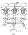
- the hydraulic steep device 6 shown in FIG. 4 comprises for each of the three post insulators 5a, 5b and 5c which the carrier 4 of the pantograph 3 on the roof 2nd of the car body 1 supports (see FIG. 4) one hydraulic each Actuator 8a or 8b or 8c.
- the hydraulic Actuators 8a and 8b and 8c are in the post insulators 5a, 5b and 5c integrated.
- the hydraulic actuators 8a, 8b and 8c each consist of a hydraulic cylinder 9a or 9b or 9c slim design, the piston rod 10a or 10b or 10c with the post insulator 5a or 5b or 5c connected is.
- the hydraulic actuator 8a or 8b or 8c is with the bottom of its housing 11a or 11b or 11c attached to the roof 2 of the car body 1.
- the hydraulic cylinders 10a, 10b and 10c By feeling the hydraulic cylinders 10a, 10b and 10c through their respective bottom inlet opening through a hydraulic line 12a 12b and 12c become the piston rods 10a, 10b and 10c extended (stroke volume of the hydraulic cylinders 9a, 9b and 9c increases) and thus the carrier 4 of the pantograph 3 is raised.
- the hydraulic cylinders can limit the existing kinetic energy 9a, 9b and 9c equipped with end position damping his.
- the hydraulic lines 12a and 13a connect the hydraulic cylinder 9a with a blocking device 14a and the hydraulic lines 12b and 13b connect the hydraulic cylinder 9b with a blocking device 14b. Furthermore connect the Hydraulic lines 12c and 13c with the hydraulic cylinder 9c a blocking device 14c.
- the blocking devices 14a, 14b and 14c prevent the carrier from dropping arbitrarily 4 of the pantograph 3.
- the blocking device 14a or 14b or 14c can also in the hydraulic actuator 8a or 8b or 8c can be integrated. In the simplest case they exist Blocking devices 14a, 14b and 14c made of simple or double acting check valves. But they can also be called hydraulic actuated clamping elements on the piston rods 10a, 10b and 10c act.
- the blocking device 14a is connected via hydraulic lines three flow valves 15a, 16a and 17a connected. Is analog the blocking device 14b via hydraulic lines with flow valves 15b, 16b and 17b and the blocking device 14c via hydraulic lines with flow valves 15c, 16c and 17c connected.
- the flow valves 15a to 17c are used to keep tracking while the wearer is moving 4 to improve the pantograph 3 again.
- the hydraulic control device 6 must be three in total different movements - namely lifting, lowering or rapid lowering of the carrier 4 - can perform.
- each of the three hydraulic actuators 8a, 8b and 8c three each the volume flow according to size and Flow valves 15a, 16a and 17a influencing the direction or 15b, 16b and 17b or 15c, 16c and 17c.
- these functions can also be used in the Hydraulic lines 21, 22 and 23 can be integrated.
- the requirements for flow synchronization are sufficient for the functions the flow valves 15a to 17c throttle resistors, whereas for highest demands also flow control valves or other volumetric dosing synchronizing devices are used can be.
- the three hydraulic actuators 8a, 8b and 8c are finally with three electro-magnetic switching valves 18, 19 and 20 connected, each switching valve 18, 19 and 20th a certain movement is assigned.
- the switching valve 18 is the embodiment of the movement sequence "Raise and lower pantograph frame" assigned.
- the switching valve 18 is for this purpose via a signal line 24 controlled.
- the switching valve 19 is via a signal line 25 controlled and is for the movement sequence "pantograph frame raise and lower quickly, emergency "responsibility.
- the switching valve 20 is via a signal line 26 controlled and is for the movement sequence "pantograph frame raise and lower "responsible.
- the connection of the hydraulic actuators 8a, 8b and 8c with the switching valves 18, 19 and 20 takes place via hydraulic lines 21, 22 and 23.
- the hydraulic line 21 connects the flow valves 15a, 15b and 15c with each other and is on the switching valve 18 out. So the three are hydraulic Actuators 8a, 8b and 8c with the electro-magnetic Switch valve 18 connected.
- the hydraulic line 22 connects the flow valves 16a, 16b and 16c together and is guided to the switching valve 19. So the three are hydraulic actuators 8a, 8b and 8c with the electromagnetic Switch valve 19 connected.
- the hydraulic line 23 connects the flow valves 17a, 17b and 17c to each other and is guided to the switching valve 20. With that they are three hydraulic actuators 8a, 8b and 8c with the electro-magnetic Switch valve 20 connected.
- switching valves 18, 19 and 20 as Two-position valves can be the second switch position for fail-save functions to be used.
- the switching valves 18, 19 and 20 are still via hydraulic lines 27 and 28 with a power supply unit 29 connected.
- the energy supply device 29 is the Hydraulic fluid stored under a certain pressure.
- the energy supply device 29 is shown in the Embodiment designed as an energy converter, the pneumatic Energy from the compressed air network 30 of the railway vehicle in hydraulic energy to supply the hydraulic Actuators 8a, 8b and 8c converted.
- both longitudinal (cylinder systems) as well as rotary (motor-pump) pressure intensifiers are used.
- the energy supply is convenient equipped with suitable storage facilities, the hydraulic fluid both at high pressure levels (Energy storage) as well as at low pressure level (container function) saves. This allows a closed hydraulic system without contact with the hydraulic fluid build up to air. Such is a closed system considerably more resistant and therefore also more durable because an aging of the hydraulic fluid through contact with the Atmospheric oxygen is prevented.
- the overall state of the system as well as individual operating states can by suitable sensors, which in detail are not shown, are monitored.
Landscapes
- Engineering & Computer Science (AREA)
- Power Engineering (AREA)
- Transportation (AREA)
- Mechanical Engineering (AREA)
- Current-Collector Devices For Electrically Propelled Vehicles (AREA)
Applications Claiming Priority (2)
| Application Number | Priority Date | Filing Date | Title |
|---|---|---|---|
| DE1999138071 DE19938071B4 (de) | 1999-08-12 | 1999-08-12 | Schienenfahrzeug |
| DE19938071 | 1999-08-12 |
Publications (1)
| Publication Number | Publication Date |
|---|---|
| EP1075980A1 true EP1075980A1 (fr) | 2001-02-14 |
Family
ID=7918061
Family Applications (1)
| Application Number | Title | Priority Date | Filing Date |
|---|---|---|---|
| EP00117441A Withdrawn EP1075980A1 (fr) | 1999-08-12 | 2000-08-11 | Capteur de courant pour un véhicule ferroviaire |
Country Status (2)
| Country | Link |
|---|---|
| EP (1) | EP1075980A1 (fr) |
| DE (1) | DE19938071B4 (fr) |
Cited By (4)
| Publication number | Priority date | Publication date | Assignee | Title |
|---|---|---|---|---|
| DE102009030218B3 (de) * | 2009-06-23 | 2010-09-23 | Bombardier Transportation Gmbh | Stromabnehmereinrichtung für ein Fahrzeugdach |
| WO2011095555A1 (fr) * | 2010-02-04 | 2011-08-11 | Siemens Aktiengesellschaft | Ensemble composé d'une caisse de wagon et d'un commutateur électrique |
| CN104129308A (zh) * | 2014-07-10 | 2014-11-05 | 南车株洲电力机车有限公司 | 一种受流器高压监控方法及系统 |
| CN111094051A (zh) * | 2017-09-01 | 2020-05-01 | 西门子交通有限公司 | 用于检验集电器的接触的方法以及集电器 |
Families Citing this family (1)
| Publication number | Priority date | Publication date | Assignee | Title |
|---|---|---|---|---|
| DE10213532A1 (de) * | 2002-03-26 | 2003-10-30 | Siemens Ag | Stützisolator |
Citations (3)
| Publication number | Priority date | Publication date | Assignee | Title |
|---|---|---|---|---|
| JPS56153901A (en) * | 1980-04-30 | 1981-11-28 | Toshiba Corp | Mounting device for apparatus such as current collector or the like for vehicle |
| JPH0622405A (ja) * | 1992-07-03 | 1994-01-28 | Toyo Electric Mfg Co Ltd | 集電装置 |
| EP0869029A2 (fr) * | 1997-04-03 | 1998-10-07 | Siemens Aktiengesellschaft | Capteur de courant pour une véhicule feroviaire |
Family Cites Families (2)
| Publication number | Priority date | Publication date | Assignee | Title |
|---|---|---|---|---|
| JPH0865808A (ja) * | 1994-08-19 | 1996-03-08 | Hitachi Ltd | 集電方法および集電装置 |
| DE29613541U1 (de) * | 1996-08-05 | 1997-06-05 | Siemens AG, 80333 München | Schienenfahrzeug |
-
1999
- 1999-08-12 DE DE1999138071 patent/DE19938071B4/de not_active Revoked
-
2000
- 2000-08-11 EP EP00117441A patent/EP1075980A1/fr not_active Withdrawn
Patent Citations (3)
| Publication number | Priority date | Publication date | Assignee | Title |
|---|---|---|---|---|
| JPS56153901A (en) * | 1980-04-30 | 1981-11-28 | Toshiba Corp | Mounting device for apparatus such as current collector or the like for vehicle |
| JPH0622405A (ja) * | 1992-07-03 | 1994-01-28 | Toyo Electric Mfg Co Ltd | 集電装置 |
| EP0869029A2 (fr) * | 1997-04-03 | 1998-10-07 | Siemens Aktiengesellschaft | Capteur de courant pour une véhicule feroviaire |
Cited By (9)
| Publication number | Priority date | Publication date | Assignee | Title |
|---|---|---|---|---|
| DE102009030218B3 (de) * | 2009-06-23 | 2010-09-23 | Bombardier Transportation Gmbh | Stromabnehmereinrichtung für ein Fahrzeugdach |
| WO2010149612A3 (fr) * | 2009-06-23 | 2011-10-27 | Bombardier Transportation Gmbh | Dispositif récepteur de courant pour toit de véhicule |
| CN102458902A (zh) * | 2009-06-23 | 2012-05-16 | 庞巴迪运输有限公司 | 车辆顶盖的集电器设备 |
| CN102458902B (zh) * | 2009-06-23 | 2015-08-19 | 庞巴迪运输有限公司 | 车辆顶盖的集电器设备 |
| WO2011095555A1 (fr) * | 2010-02-04 | 2011-08-11 | Siemens Aktiengesellschaft | Ensemble composé d'une caisse de wagon et d'un commutateur électrique |
| CN104129308A (zh) * | 2014-07-10 | 2014-11-05 | 南车株洲电力机车有限公司 | 一种受流器高压监控方法及系统 |
| CN104129308B (zh) * | 2014-07-10 | 2016-05-11 | 南车株洲电力机车有限公司 | 一种受流器高压监控方法及系统 |
| CN111094051A (zh) * | 2017-09-01 | 2020-05-01 | 西门子交通有限公司 | 用于检验集电器的接触的方法以及集电器 |
| CN111094051B (zh) * | 2017-09-01 | 2023-05-05 | 西门子交通有限公司 | 用于检验集电器的接触的方法以及集电器 |
Also Published As
| Publication number | Publication date |
|---|---|
| DE19938071A1 (de) | 2001-02-22 |
| DE19938071B4 (de) | 2006-04-13 |
Similar Documents
| Publication | Publication Date | Title |
|---|---|---|
| EP3790759B1 (fr) | Collecteur de courant pour véhicule tracteur électrique non ferroviaire, véhicule tracteur muni d'un tel collecteur de courant, et procédé permettant de faire fonctionner un tel collecteur de courant | |
| EP3347231B1 (fr) | Unité de positionnement pour une station de charge et procédé pour la mise en contact | |
| EP0453752A1 (fr) | Autobus, en particulier à plate-forme surbaissée | |
| EP0331101A2 (fr) | Jambe de suspension pour véhicules à grue | |
| WO2019214956A1 (fr) | Repose-pied modulaire pour un poste de conduite d'un véhicule sur rails | |
| EP1075980A1 (fr) | Capteur de courant pour un véhicule ferroviaire | |
| EP2346710B1 (fr) | Collecteur de courant pour véhicule ferroviaire | |
| EP1289792B1 (fr) | Pantographe pour vehicule ferroviaire a traction electrique | |
| DE69120450T2 (de) | Scherenstromabnehmer | |
| DE102013021803A1 (de) | Aufstieg zur Fahrzeugtür eines Kraftfahrzeugs | |
| EP1045770B1 (fr) | Systeme hydraulique pour automobile presentant un toit repliable | |
| EP4122746A1 (fr) | Collecteur de courant pour véhicule routier électrique ou hybride-électrique | |
| DE4433050A1 (de) | Anbaugerät für Hublader mit an aufzunehmenden Nutzlasteinheiten anpreßbaren Klammerarmen | |
| EP2311684B1 (fr) | Prise de courant | |
| DE2834480C2 (de) | Steuereinrichtung eines Schaufelladers od.dgl. | |
| EP0356835B1 (fr) | Pantographe pour véhicules à propulsion électrique comportant un dispositif de descente rapide | |
| DE9421460U1 (de) | Stromabnehmer | |
| DE19957356C1 (de) | Vorrichtung zum Erden eines Fahrdrahtes | |
| DE4412215C2 (de) | Tragbühne für Ambulanz-Liegen | |
| DE102021207225A1 (de) | Stromabnehmer für ein elektrisch oder hybridelektrisch angetriebenes Straßenfahrzeug sowie Straßenfahrzeug mit einem solchen Stromabnehmer | |
| EP1010575A1 (fr) | Système de hayon élévateur avec au moins un actionneur | |
| DE102021206840A1 (de) | Stromabnehmer für ein elektrisch oder hybridelektrisch angetriebenes Straßenfahrzeug sowie Straßenfahrzeug mit einem solchen Stromabnehmer | |
| EP0968898A2 (fr) | Véhicule ferroviaire | |
| DE1203617B (de) | Steuerung des Verteilers fuer das Hydraulik-Mittel von hydraulisch-pneumatischen Fahrzeugfederungen | |
| EP1445145A1 (fr) | Sytème de hayon élévateur avec au moins un actionneur pour pivotement et élévation |
Legal Events
| Date | Code | Title | Description |
|---|---|---|---|
| PUAI | Public reference made under article 153(3) epc to a published international application that has entered the european phase |
Free format text: ORIGINAL CODE: 0009012 |
|
| AK | Designated contracting states |
Kind code of ref document: A1 Designated state(s): AT CH DE FR IT LI |
|
| AX | Request for extension of the european patent |
Free format text: AL;LT;LV;MK;RO;SI |
|
| 17P | Request for examination filed |
Effective date: 20010814 |
|
| AKX | Designation fees paid |
Free format text: AT CH DE FR IT LI |
|
| STAA | Information on the status of an ep patent application or granted ep patent |
Free format text: STATUS: THE APPLICATION IS DEEMED TO BE WITHDRAWN |
|
| 18D | Application deemed to be withdrawn |
Effective date: 20070301 |