EP1076143B1 - Appareil électroménager avec un élément de verrouillage - Google Patents
Appareil électroménager avec un élément de verrouillage Download PDFInfo
- Publication number
- EP1076143B1 EP1076143B1 EP00116041A EP00116041A EP1076143B1 EP 1076143 B1 EP1076143 B1 EP 1076143B1 EP 00116041 A EP00116041 A EP 00116041A EP 00116041 A EP00116041 A EP 00116041A EP 1076143 B1 EP1076143 B1 EP 1076143B1
- Authority
- EP
- European Patent Office
- Prior art keywords
- lock
- locking
- fastening part
- connecting part
- movement direction
- Prior art date
- Legal status (The legal status is an assumption and is not a legal conclusion. Google has not performed a legal analysis and makes no representation as to the accuracy of the status listed.)
- Expired - Lifetime
Links
- 239000000463 material Substances 0.000 claims description 6
- 230000037431 insertion Effects 0.000 claims 1
- 238000003780 insertion Methods 0.000 claims 1
- 238000009434 installation Methods 0.000 description 2
- 239000002184 metal Substances 0.000 description 2
- 239000012858 resilient material Substances 0.000 description 1
Images


Classifications
-
- E—FIXED CONSTRUCTIONS
- E05—LOCKS; KEYS; WINDOW OR DOOR FITTINGS; SAFES
- E05C—BOLTS OR FASTENING DEVICES FOR WINGS, SPECIALLY FOR DOORS OR WINDOWS
- E05C19/00—Other devices specially designed for securing wings, e.g. with suction cups
- E05C19/06—Other devices specially designed for securing wings, e.g. with suction cups in which the securing part if formed or carried by a spring and moves only by distortion of the spring, e.g. snaps
Definitions
- the invention relates to a household appliance having a locking element, by means of which two components that are movable relative to one another can be locked to one another in a releasable manner, according to claim 1.
- Locking elements in the household appliance according to the invention can be used for any purpose, in particular for locking frames, lids, flaps, windows, doors, sliders, drawers, boxes, cassettes and similar, depending pivotally or linearly displaceable components of household appliances, e.g. of cooker hoods.
- the US 21 23 588 shows a generic subject for the subject of the application.
- a resilient locking member which is secured to one component with a fastener and which has a latch at another portion for engaging a cover above a refrigerator with the latch.
- the cover member has a through opening (49) through which a pin or other tool can be inserted, with which can be pressed on a tab disposed adjacent to the latch to unlock the locking element.
- the invention enables the problem to be solved, to develop a locking element for a household appliance, which is easy to install manually, must be attached only to one of the two components to be locked together, in the manner of a push button is actuated, and preferably from a one-piece body of material to produce is.
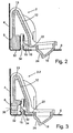
- Fig. 1 shows in the locked position, and Fig. 2 in the unlocked position, a cross section of a locking element 2 for a household appliance according to the invention by which two relatively movable components 4 and 6 are releasably locked together.
- the locking element 2 includes a fastening part 8 (or a plurality of parallel juxtaposed fastening parts) for attachment to the one component 4; a latch 10 (or a plurality of juxtaposed bars) for locking the respective other component 6; a connecting part 12 (or a plurality of juxtaposed connecting parts), which connects the latch 10 with the fastening part 8, wherein the bolt 10 protrudes in its locking movement direction 14 of the connecting part 12 and wherein the connecting part 12 at least partially, preferably over its entire length from the fastening part.
- the fastening part 8, the bolt 10 and the connecting part 12 consist in the preferred embodiment together of a one-piece material body made of plastic.
- a one-piece material body made of plastic.
- multi-part embodiments and other materials e.g. Sheet metal, possible.
- the connecting part 12 has two at an angle of less than 90 ° to each other arranged leg 12-1 and 12-2, which are connected to each other in the angle top 13 and in the angular plane against each other by manual pressure on the push button 18 or can be moved by a transverse force of the other component 6 on an inclined ramp surface 15 of the bolt 10.
- the fastening part 8 is on one leg 12-1 and the bolt 10 and the push button 18 are provided on the other leg 12-2 of the connecting part 12 each at a distance from the angle tip 13.
- the bolt 10 protrudes from the other leg 12-2 in the direction of a leg 12-1 away.
- the latch 10 is disposed opposite to the attachment part 8 and its locking movement direction 14 is directed against the attachment part 8.
- the push button 18 is formed on an extension 22 of the connecting part 12 which extends at or close to the latch 10 opposite to the locking movement direction 14 away from the bolt 10.
- the push button 18 is provided with a manually operable pressure surface 24 which extends obliquely to the locking movement direction 14, pointing to the same side as the latch 10 and its locking movement direction 14, ie opposite to the manual operating force required to lock the latch 10 against the elastic force of the connecting part 12th from the locking position of Fig. 1 in the unlocked position of Fig. 2 to press.
- the push button 18, at least its pressure surface 24 is located with respect to the required for the locking and unlocking spring-elastic part 12-1, 12-2, 13 of the connecting part 12 on the side facing away from the bolt 10th
- the fastening part 8 is arranged at the end remote from the angle tip 13 of the one leg 12-1 of the connecting part 12.
- the fastening part 8 is provided with at least one detent projection 26 for locking into a detent opening 28 of the one component 4 and thus for fastening the connecting part 12 to this component 4.
- the latching projection 26 may be resilient, either by resilient material of the locking element 2 and / or by forming the detent projection 16 on a resiliently transversely movable mounting portion on the fastening part 8.
- the component 4 has a 33 of a base leg U-shaped inwardly to the locking element 2 towards bent portion 32 in which the fastening part 8 from the inside with sliding seat can be inserted.
- the notch 28 is formed in the inwardly projecting free leg 31 of the U-shaped portion 32 opposite a latch receiving opening 34, which latter is formed in a parallel to a leg 31 inwardly projecting leg 35 of the other component 6 and for receiving and Locking the bolt 10 is used.
- At least the leg 31 of the U-shaped portion 32 in the transverse direction is resilient, so that the fastening part 8 in the U-shaped portion 32 with lateral guidance, preferably with lateral tension, can be used while the locking projection 26th can engage in the latch opening 28. As a result, the fastening part 8 is held wobble-free in the U-shaped region 32.
- the fastening part 8 is attached to a component 4, the bolt 10 protrudes in the locked state of Fig. 1 through the locking hole 34 through and is preferably supported on the latch projection 26 and can be moved by manual pressure on the push button 18 away from the fastening part 8 from the locking hole 34 out in the unlocked position of Fig. 2.
- the push button 18 protrudes through a push button opening 38 therethrough.
- the locking opening 34 is formed in the transverse to the locking direction 14 in the interior of a device extending leg 35 of the device 6.
- the push-button opening 38 is formed in a base leg 44 of the component 6, which extends parallel to the locking movement direction 14 and at right angles to its inwardly projecting leg 35
- one or more openings 36 may be provided in the fastening part 8 for attachment to the one component 4 by means of a connecting element such as a screw.
- the two components 4 and 6 are made of sheet metal, but may also consist of a different material.
- one component 4 is a stationary component and the other component 6 is pivotable about a pivot axis relative to the stationary component 4.
- This may be a pivot axis 46, which extends at right angles to the locking movement direction 14 as shown in FIG. 1, but it may also be shown in FIG. 4 a pivot axis 48 which extends parallel to the locking movement direction 14 of the bolt 10.
- the mobility of the components 4 and 6 can be reversed, so that the one component 4, the movable and the other component 6 is the stationary component.
- the fastening part 8 is fastened to a movable component 6 can be and the locking hole 34 and the push button opening 38 may be formed in a stationary member 4 to receive the latch 10 and the push button 18.
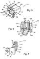
- FIGS. 5, 6 and 7 at the end remote from the fastening part 8 of the connecting part 12, two or more bars 10 may be provided parallel to each other at a distance side by side, which are designated therein by the reference numerals 10A and 10B.
- FIGS. 5, 6 and 7 show that the fastening part 8 can be connected to the at least one bar 10 or 10A, 10B instead of a single connecting part 12 by a plurality of connecting parts arranged parallel to one another at a distance or the connecting part 12 at least partially a plurality of parallel spaced apart juxtaposed sections may be divided, for example in the angled top 13 by the two parts 13A and 13B, which connect the two legs 12-1 and 12-2 of the connecting part 12 together.
- the fastener 8 may be provided with one or more mounting apertures 36 for attachment to a component 4 or 6, or with one or more detent projections 26 as shown in FIG. 1.
- the connector 12 is at its end remote from the fastener 8 in addition to the fasteners 10A and 10B 10B also provided with a push button 18, which according to the push button of Figs. 1 and 2 may be formed on an extension 22 of the connecting part 12.
- FIGS. 1, 2 and 4 are denoted by 2, the locking element of FIG. 3 by 2-2, and the locking element of FIGS. 5, 6 and 7 by 2-3. Identical or substantially the same, functionally corresponding parts are provided with the same reference numerals.
- the manual pressure surface 24 of the push button 18 may be formed parallel or perpendicular to the locking movement direction 14 on the push button 18.
- the extension 22 of the connecting part 12 can extend beyond the bolt 10 at right angles or obliquely to the locking movement direction 14 and the push button 18 can move in the locking movement direction 14, i. in the same direction as the latch 10, away from it.
Landscapes
- Engineering & Computer Science (AREA)
- Mechanical Engineering (AREA)
- Connection Of Plates (AREA)
- Hooks, Suction Cups, And Attachment By Adhesive Means (AREA)
Claims (8)
- Appareil ménager avec un élément de verrouillage, par lequel deux composants (4, 6) mobiles l'un par rapport à l'autre peuvent être verrouillés entre eux de façon amovible, contenant
au moins une partie de fixation (8) pour la fixation sur l'un des deux composants (4) ;
au moins un verrou (10) pour le verrouillage de l'autre composant (6) concerné, au moins une partie de liaison (12), qui relie le verrou (10) à la partie de fixation (8), le verrou (10) dépassant de la partie de liaison (12) dans son sens de déplacement de verrouillage (14) et la partie de liaison (12) étant flexible à la façon d'un ressort au moins dans un tronçon, de sorte que le verrou (10) est poussé du fait de cette élasticité de ressort conjointement avec la zone, reliée au verrou, de la partie de liaison (12) dans le sens de déplacement de verrouillage (14) par rapport à la partie de fixation (8) dans une position de verrouillage et peut être déplacé manuellement dans le sens contraire à la force de ressort de la partie de liaison (12) dans le sens contraire au sens de déplacement de verrouillage (14) dans une position de déverrouillage, le verrou (10) étant disposé en face de la partie de fixation (8) et son sens de déplacement de verrouillage (14) étant orienté dans le sens contraire à la partie de fixation (8) ;
un bouton à pression (18) pour le déplacement manuel du verrou (10) dans le sens contraire à son sens de déplacement de verrouillage (14) et dans le sens contraire à la force de ressort de la partie de liaison (12) élastique comme un ressort dans la position de déverrouillage, la partie de liaison (12) présentant deux branches (12-1, 12-2) disposées l'une par rapport à l'autre dans un angle de moins de 90°, lesquelles branches sont reliées entre elles dans la pointe d'angle (13), et qui peuvent être déplacées manuellement à la façon d'un ressort l'une par rapport à l'autre dans le plan d'angle du fait de ladite élasticité de ressort, la partie de fixation (8) étant prévue sur une branche (12-1) et le verrou (10) ainsi que le bouton à pression (18) étant prévus sur l'autre branche (12-2), et en ce que le verrou (10) dépasse de l'autre branche (12-2) en direction d'une branche (12-1), une ouverture de bouton à pression (38) étant prévue dans les autres des composants (4, 6), ouverture par laquelle le bouton à pression (18) dépasse vers le côté extérieur du composant (4, 6) et est accessible pour l'actionnement par le côté extérieur du composant (4, 6). - Appareil ménager selon la revendication 1, caractérisé en ce que la partie de fixation (8), le verrou (10) et la partie de liaison (12) sont ensemble à base d'un corps de matériau d'une seule pièce.
- Appareil ménager selon l'une quelconque des revendications précédentes, caractérisé en ce que le bouton à pression (18) est disposé en un endroit davantage éloigné de la partie de fixation (8) que le verrou (10).
- Appareil ménager selon l'une quelconque des revendications précédentes, caractérisé en ce que le bouton à pression (18) dépasse transversalement au sens de déplacement de verrouillage (14) du verrou (10) au-delà de la position du verrou (10) du côté du verrou, qui est opposé au côté du verrou sur lequel le verrou est relié par la partie de liaison (12) à la partie de fixation (8).
- Appareil ménager selon l'une quelconque des revendications précédentes, caractérisé en ce que le bouton à pression (18) est doté d'une surface de pression (24) manuelle, laquelle s'étend en biais par rapport au sens de déplacement de verrouillage (14) du verrou (10).
- Appareil ménager selon l'une quelconque des revendications précédentes, caractérisé en ce que la partie de fixation (8) est dotée d'au moins un ergot d'encliquetage (26) pour l'encliquetage sur l'un des composants (4).
- Appareil ménager selon l'une quelconque des revendications précédentes, caractérisé en ce que la partie de fixation (8) présente au moins une ouverture (36) pour l'insertion d'un élément de verrouillage reliant un composant (4).
- Utilisation d'au moins un appareil ménager avec un élément de verrouillage selon l'une quelconque des revendications précédentes, l'élément de verrouillage étant utilisé pour le verrouillage de cadres, couvercles, clapets, fenêtres, portes, coulisseaux, tiroirs, caisses, cassettes et composants (6) similaires, disposés chacun de façon basculante et/ou coulissante dans le sens linéaire, de l'appareil ménager.
Applications Claiming Priority (2)
| Application Number | Priority Date | Filing Date | Title |
|---|---|---|---|
| DE1999137625 DE19937625A1 (de) | 1999-08-10 | 1999-08-10 | Verriegelungselement |
| DE19937625 | 1999-08-10 |
Publications (2)
| Publication Number | Publication Date |
|---|---|
| EP1076143A1 EP1076143A1 (fr) | 2001-02-14 |
| EP1076143B1 true EP1076143B1 (fr) | 2007-09-12 |
Family
ID=7917780
Family Applications (1)
| Application Number | Title | Priority Date | Filing Date |
|---|---|---|---|
| EP00116041A Expired - Lifetime EP1076143B1 (fr) | 1999-08-10 | 2000-07-26 | Appareil électroménager avec un élément de verrouillage |
Country Status (3)
| Country | Link |
|---|---|
| EP (1) | EP1076143B1 (fr) |
| DE (2) | DE19937625A1 (fr) |
| ES (1) | ES2292391T3 (fr) |
Families Citing this family (2)
| Publication number | Priority date | Publication date | Assignee | Title |
|---|---|---|---|---|
| RU2239039C1 (ru) * | 2003-03-25 | 2004-10-27 | Федеральное государственное унитарное предприятие "Государственный космический научно-производственный центр им. М.В.Хруничева" | Замок |
| DE102016107097B4 (de) * | 2016-04-18 | 2025-10-30 | Miele & Cie. Kg | Dunstabzugshaube und Verfahren zum Montieren einer Dunstabzugshaube |
Citations (1)
| Publication number | Priority date | Publication date | Assignee | Title |
|---|---|---|---|---|
| US2123588A (en) * | 1936-05-15 | 1938-07-12 | Gen Motors Corp | Refrigerating apparatus |
Family Cites Families (8)
| Publication number | Priority date | Publication date | Assignee | Title |
|---|---|---|---|---|
| US2520725A (en) * | 1946-08-26 | 1950-08-29 | Tinnerman Products Inc | Support construction and fastening device therefor |
| DE2121853C3 (de) * | 1971-05-04 | 1979-10-18 | Siemens Ag, 1000 Berlin Und 8000 Muenchen | Schnappverschluß für Gehäuseabdeckungen |
| GB1378668A (en) * | 1973-08-23 | 1974-12-27 | Mothercare Ltd | Catch |
| US4865366A (en) * | 1988-07-05 | 1989-09-12 | Whirlpool Corporation | Toe panel retainer clip for dryer |
| DE3940061C2 (de) * | 1989-12-04 | 1994-06-30 | Bauer Hans Juergen | Türschloß |
| US5158329A (en) * | 1991-09-20 | 1992-10-27 | Southco, Inc. | Slam latch |
| DE4421022A1 (de) * | 1994-06-16 | 1995-12-21 | Klaus Rehahn Gmbh & Co Kg | Schnappverschluß für Behälter |
| US6053544A (en) * | 1998-05-11 | 2000-04-25 | White Consoldiated Industries, Inc. | Locking handle for refrigerators |
-
1999
- 1999-08-10 DE DE1999137625 patent/DE19937625A1/de not_active Ceased
-
2000
- 2000-07-26 DE DE50014646T patent/DE50014646D1/de not_active Expired - Lifetime
- 2000-07-26 EP EP00116041A patent/EP1076143B1/fr not_active Expired - Lifetime
- 2000-07-26 ES ES00116041T patent/ES2292391T3/es not_active Expired - Lifetime
Patent Citations (1)
| Publication number | Priority date | Publication date | Assignee | Title |
|---|---|---|---|---|
| US2123588A (en) * | 1936-05-15 | 1938-07-12 | Gen Motors Corp | Refrigerating apparatus |
Also Published As
| Publication number | Publication date |
|---|---|
| ES2292391T3 (es) | 2008-03-16 |
| DE50014646D1 (de) | 2007-10-25 |
| EP1076143A1 (fr) | 2001-02-14 |
| DE19937625A1 (de) | 2001-02-15 |
Similar Documents
| Publication | Publication Date | Title |
|---|---|---|
| DE69804077T2 (de) | Befestigungsmittel für lösbare Verbindungen von Platten | |
| DE60301799T2 (de) | Vorrichtung zum Anordnen und Auslieferung von Komponenten | |
| EP3727090B1 (fr) | Paroi latérale de tiroir pourvu de profilé de couverture | |
| DE202008011505U1 (de) | Schubkasten | |
| DE202005007586U1 (de) | Behälter mit Rastverschluss | |
| WO2016177559A1 (fr) | Charnière de meuble dotée d'un amortisseur | |
| EP1723298A1 (fr) | Fermeture a fixer dans des ouvertures menagees dans une paroi mince | |
| DE9212950U1 (de) | Treibstangenbeschlag für Fenster, Türen o.dgl. | |
| DE3336952A1 (de) | Druckknopfschloss, insbesondere fuer verschlussklappen von handschuhfaechern in kraftfahrzeugen | |
| EP3535824B1 (fr) | Support de jeu de barres et ensemble correspondant | |
| DE102008050477A1 (de) | Kochgeschirr mit abnehmbarem Griff- oder Stielelement | |
| DE102006016277A1 (de) | Schnellverschluss | |
| EP0754827A2 (fr) | Dispositif pour la fixation amovible et axialement non coulissante d'une poignée sur un élément de palier, notamment pour une poignée de porte ou fenêtre | |
| DE102015116612A1 (de) | Beschlag für eine Schiebetür und Verfahren zur Montage einer Schiebetür | |
| DE19501059C2 (de) | Griff für eine Sanitärarmatur | |
| EP2048378B1 (fr) | Elément d'encliquetage et dispositif à cliquet | |
| DE10118394A1 (de) | Verschlußvorrichtung | |
| DE102006030769B3 (de) | Vorrichtung zur Aufnahme eines Kraftfahrzeug-Wagenhebers | |
| DE102019103655A1 (de) | Schubkasten | |
| DE3800373C2 (fr) | ||
| EP1076143A1 (fr) | Elément de verrouillage | |
| DE60301773T9 (de) | Verfahren und Gerät für die Montage eines Haushaltgeräts in einem Schrank | |
| DE4240463A1 (en) | Coupling to extend switch actuation plunger - has in=line coupling with spring clip inserted for coupling to switch body | |
| AT503457B1 (de) | Scharnier für die verschwenkbare anlenkung von klappen oder türflügeln am korpus von möbelstücken | |
| EP1365092B1 (fr) | Fermeture à pêne coulissante pour un capot pivotant d'un véhicule |
Legal Events
| Date | Code | Title | Description |
|---|---|---|---|
| PUAI | Public reference made under article 153(3) epc to a published international application that has entered the european phase |
Free format text: ORIGINAL CODE: 0009012 |
|
| AK | Designated contracting states |
Kind code of ref document: A1 Designated state(s): DE ES FR GB IT SE |
|
| AX | Request for extension of the european patent |
Free format text: AL;LT;LV;MK;RO;SI |
|
| 17P | Request for examination filed |
Effective date: 20010814 |
|
| AKX | Designation fees paid |
Free format text: DE ES FR GB IT SE |
|
| 17Q | First examination report despatched |
Effective date: 20020227 |
|
| RAP1 | Party data changed (applicant data changed or rights of an application transferred) |
Owner name: BSH BOSCH UND SIEMENS HAUSGERAETE GMBH |
|
| RTI1 | Title (correction) |
Free format text: HOUSEHOLD APPLIANCE WITH A LOCKING ELEMENT |
|
| GRAP | Despatch of communication of intention to grant a patent |
Free format text: ORIGINAL CODE: EPIDOSNIGR1 |
|
| GRAS | Grant fee paid |
Free format text: ORIGINAL CODE: EPIDOSNIGR3 |
|
| GRAA | (expected) grant |
Free format text: ORIGINAL CODE: 0009210 |
|
| AK | Designated contracting states |
Kind code of ref document: B1 Designated state(s): DE ES FR GB IT SE |
|
| REG | Reference to a national code |
Ref country code: GB Ref legal event code: FG4D Free format text: NOT ENGLISH |
|
| REF | Corresponds to: |
Ref document number: 50014646 Country of ref document: DE Date of ref document: 20071025 Kind code of ref document: P |
|
| REG | Reference to a national code |
Ref country code: ES Ref legal event code: FG2A Ref document number: 2292391 Country of ref document: ES Kind code of ref document: T3 |
|
| GBV | Gb: ep patent (uk) treated as always having been void in accordance with gb section 77(7)/1977 [no translation filed] | ||
| PG25 | Lapsed in a contracting state [announced via postgrant information from national office to epo] |
Ref country code: GB Free format text: LAPSE BECAUSE OF FAILURE TO SUBMIT A TRANSLATION OF THE DESCRIPTION OR TO PAY THE FEE WITHIN THE PRESCRIBED TIME-LIMIT Effective date: 20070912 |
|
| PG25 | Lapsed in a contracting state [announced via postgrant information from national office to epo] |
Ref country code: SE Free format text: LAPSE BECAUSE OF FAILURE TO SUBMIT A TRANSLATION OF THE DESCRIPTION OR TO PAY THE FEE WITHIN THE PRESCRIBED TIME-LIMIT Effective date: 20071212 |
|
| PLBE | No opposition filed within time limit |
Free format text: ORIGINAL CODE: 0009261 |
|
| STAA | Information on the status of an ep patent application or granted ep patent |
Free format text: STATUS: NO OPPOSITION FILED WITHIN TIME LIMIT |
|
| 26N | No opposition filed |
Effective date: 20080613 |
|
| PGFP | Annual fee paid to national office [announced via postgrant information from national office to epo] |
Ref country code: ES Payment date: 20100726 Year of fee payment: 11 |
|
| PGFP | Annual fee paid to national office [announced via postgrant information from national office to epo] |
Ref country code: IT Payment date: 20100727 Year of fee payment: 11 Ref country code: DE Payment date: 20100731 Year of fee payment: 11 |
|
| PG25 | Lapsed in a contracting state [announced via postgrant information from national office to epo] |
Ref country code: DE Free format text: LAPSE BECAUSE OF NON-PAYMENT OF DUE FEES Effective date: 20120201 |
|
| REG | Reference to a national code |
Ref country code: DE Ref legal event code: R119 Ref document number: 50014646 Country of ref document: DE Effective date: 20120201 |
|
| PG25 | Lapsed in a contracting state [announced via postgrant information from national office to epo] |
Ref country code: IT Free format text: LAPSE BECAUSE OF NON-PAYMENT OF DUE FEES Effective date: 20110726 |
|
| REG | Reference to a national code |
Ref country code: ES Ref legal event code: FD2A Effective date: 20121207 |
|
| PG25 | Lapsed in a contracting state [announced via postgrant information from national office to epo] |
Ref country code: ES Free format text: LAPSE BECAUSE OF NON-PAYMENT OF DUE FEES Effective date: 20110727 |
|
| PG25 | Lapsed in a contracting state [announced via postgrant information from national office to epo] |
Ref country code: FR Free format text: LAPSE BECAUSE OF FAILURE TO SUBMIT A TRANSLATION OF THE DESCRIPTION OR TO PAY THE FEE WITHIN THE PRESCRIBED TIME-LIMIT Effective date: 20070912 |