EP1076177B1 - Procédé de démarrage d'un moteur à combustion interne à allumage commandé - Google Patents
Procédé de démarrage d'un moteur à combustion interne à allumage commandé Download PDFInfo
- Publication number
- EP1076177B1 EP1076177B1 EP20000402263 EP00402263A EP1076177B1 EP 1076177 B1 EP1076177 B1 EP 1076177B1 EP 20000402263 EP20000402263 EP 20000402263 EP 00402263 A EP00402263 A EP 00402263A EP 1076177 B1 EP1076177 B1 EP 1076177B1
- Authority
- EP
- European Patent Office
- Prior art keywords
- speed
- pressure
- engine
- threshold
- intake manifold
- Prior art date
- Legal status (The legal status is an assumption and is not a legal conclusion. Google has not performed a legal analysis and makes no representation as to the accuracy of the status listed.)
- Expired - Lifetime
Links
- 238000000034 method Methods 0.000 title claims description 36
- 230000008569 process Effects 0.000 title claims description 24
- 238000002485 combustion reaction Methods 0.000 title claims description 16
- 238000002347 injection Methods 0.000 claims description 11
- 239000007924 injection Substances 0.000 claims description 11
- 239000000446 fuel Substances 0.000 claims description 9
- 230000007480 spreading Effects 0.000 claims description 2
- 230000001960 triggered effect Effects 0.000 claims description 2
- 239000007858 starting material Substances 0.000 description 10
- 238000010586 diagram Methods 0.000 description 7
- 230000001276 controlling effect Effects 0.000 description 3
- 238000004519 manufacturing process Methods 0.000 description 2
- 239000000203 mixture Substances 0.000 description 2
- 230000009467 reduction Effects 0.000 description 2
- 230000001105 regulatory effect Effects 0.000 description 2
- 241000135309 Processus Species 0.000 description 1
- 230000009471 action Effects 0.000 description 1
- 238000012550 audit Methods 0.000 description 1
- 230000003416 augmentation Effects 0.000 description 1
- 230000006835 compression Effects 0.000 description 1
- 238000007906 compression Methods 0.000 description 1
- 238000011217 control strategy Methods 0.000 description 1
- 239000000498 cooling water Substances 0.000 description 1
- 230000009849 deactivation Effects 0.000 description 1
- 230000000881 depressing effect Effects 0.000 description 1
- 230000000994 depressogenic effect Effects 0.000 description 1
- 230000037213 diet Effects 0.000 description 1
- 235000005911 diet Nutrition 0.000 description 1
- 239000007789 gas Substances 0.000 description 1
- 230000007246 mechanism Effects 0.000 description 1
- 230000007935 neutral effect Effects 0.000 description 1
- 210000000056 organ Anatomy 0.000 description 1
- 238000005086 pumping Methods 0.000 description 1
- 230000007704 transition Effects 0.000 description 1
Images

Classifications
-
- F—MECHANICAL ENGINEERING; LIGHTING; HEATING; WEAPONS; BLASTING
- F02—COMBUSTION ENGINES; HOT-GAS OR COMBUSTION-PRODUCT ENGINE PLANTS
- F02D—CONTROLLING COMBUSTION ENGINES
- F02D41/00—Electrical control of supply of combustible mixture or its constituents
- F02D41/02—Circuit arrangements for generating control signals
- F02D41/04—Introducing corrections for particular operating conditions
- F02D41/06—Introducing corrections for particular operating conditions for engine starting or warming up
- F02D41/062—Introducing corrections for particular operating conditions for engine starting or warming up for starting
-
- F—MECHANICAL ENGINEERING; LIGHTING; HEATING; WEAPONS; BLASTING
- F02—COMBUSTION ENGINES; HOT-GAS OR COMBUSTION-PRODUCT ENGINE PLANTS
- F02N—STARTING OF COMBUSTION ENGINES; STARTING AIDS FOR SUCH ENGINES, NOT OTHERWISE PROVIDED FOR
- F02N11/00—Starting of engines by means of electric motors
- F02N11/08—Circuits specially adapted for starting of engines
-
- F—MECHANICAL ENGINEERING; LIGHTING; HEATING; WEAPONS; BLASTING
- F02—COMBUSTION ENGINES; HOT-GAS OR COMBUSTION-PRODUCT ENGINE PLANTS
- F02N—STARTING OF COMBUSTION ENGINES; STARTING AIDS FOR SUCH ENGINES, NOT OTHERWISE PROVIDED FOR
- F02N2300/00—Control related aspects of engine starting
- F02N2300/20—Control related aspects of engine starting characterised by the control method
- F02N2300/2011—Control involving a delay; Control involving a waiting period before engine stop or engine start
Definitions
- the present invention relates to a method of automatic start of an internal combustion engine at controlled ignition for a motor vehicle.
- a vehicle powered by a internal combustion engine (also referred to below) briefly “heat engine”) is equipped with two machines electric, one ensuring starting (starter) and the other the supply of the vehicle's on-board network (alternator).
- the starting torque is determined by calculating a torque setpoint, then by a complex set of calculations and adjustments (involving both machines and a planetary gear train), we gradually increases the torque of the engine until the calculated setpoint torque is obtained and simultaneously reduces the torque supplied by the two machines electric.
- the object of the present invention is to provide a significantly easier automatic start-up process than the process described in the prior art, by making intervene a single electric machine, either switchable starter or alternator, either used as a starter only, the latter case corresponding to the configuration classic where an alternator is provided next to the starter for the production of electrical energy.
- the invention also aims to provide such a method which ensures so optimal reduction of consumption and emission harmful gases during the starting of the engine.
- the method according to the invention can be implemented whether it is a configuration with an electric machine with mixed function (starter and alternator) or a configuration where two machines electric are provided, one for starting and the other for the production of electrical energy on board of the vehicle.
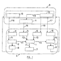
- Figure 1 relates to an exemplary embodiment of a device for implementing the method according to the invention.
- rectangle A symbolizes the engine internal combustion with controlled ignition with all its associated organs insofar as they are important for understanding the invention.
- Engine A has a number n of cylinders 1 in which is conventionally carried out the combustion of a air / fuel mixture (petrol), according to an ignition order predetermined.
- the cylinders are connected to a manifold intake 2 and an exhaust manifold 3.
- the intake manifold 2 is connected to a manifold of admission (not shown).
- At least one air actuator 4 such than a motorized throttle to regulate the air flow and therefore the mass of air which circulates towards the cylinders 1 and which, from less during part of the start-up phase, succeeds not modified in exhaust 3 (arrows f1).
- a special motorized valve is provided in parallel to this butterfly in order to regulate the mass of air admitted in low loads (in idle for example).
- the fuel is injected into intake manifolds (not shown) with injectors 5, selectively for cylinders 1.
- injectors 5 selectively for cylinders 1.
- the arrow f2 thus symbolizes the mass of fuel injected.
- the air / fuel mixture can be ignited in the cylinders 1 by an ignition device 6, arrow f3 symbolizing the command of this operation.
- the pistons are moving in cylinders 1 cause the rotation of a crankshaft 7, the engine torque thus transmitted being symbolized by the arrow f4.
- a pressure sensor 8 is placed in the manifold intake to measure the air pressure.
- Another sensor 9 or speed sensor is coupled to crankshaft 7 to measure the speed of rotation.
- the crankshaft 7 is also coupled to a machine electric 10 which, in the described embodiment, serves as both a starter and an energy generator of the whole. This machine cooperates with a battery (not shown), or to draw energy from it start-up, or to inject the energy produced when the machine operates as a generator after the end of startup process.
- the starting torque applied to the crankshaft 7 is symbolized by the arrow f5.
- the invention is not limited to a configuration in which the machine electric serves as both a starter and an alternator. he is also possible to apply it as part of a classic configuration in which these two functions are provided by independent electric machines.
- Motor A is controlled by a symbolized computer by rectangle B in figure 1.
- the term calculator can here collectively designate several computers to dedicated tasks that are functionally coupled to them to each other.
- the computer B prepares, in a conventional manner, the control strategies 11 of motor A, in particular in generating injection duration signals which are applied to injectors 5 via the f6 link.
- this computer B also controls an engine start strategy 12 by developing, during the start-up phase, a electric machine start / stop control signal 10 then operating as a motor (connection f7), a signal ignition advance (link f8) applied to the device ignition 6 and specific to the start-up phase and a injection start command signal (link f9) taken into account by command strategy 11 also during the start-up phase.
- a electric machine start / stop control signal 10 then operating as a motor (connection f7), a signal ignition advance (link f8) applied to the device ignition 6 and specific to the start-up phase and a injection start command signal (link f9) taken into account by command strategy 11 also during the start-up phase.
- the computer B orders, for start-up, a regulation strategy 13 pressure, the resulting signal being intended to be applied to air actuator 4 (connection f10).
- the diagrams a to f of figure 2 illustrate the start-up process between instant t0 at which this one begins and an instant t8 at which it ends and the engine reaches its engine speed idle stabilized.
- Diagrams represent by function of time t: in a) the speed R of the heat engine, in b) the pressure Pc in the intake manifold 2, in c) the degree of opening Da of the air actuator 4, in d) the Di command of injection time per engine time of cylinders 1, in e) the ignition advance Av and in f) a parameter Cm representing the running command of the electric machine 10.
- the starting method according to the invention is used preferably to allow quick starts of the engine A after stopping the motor vehicle in specific traffic situations (traffic lights red, for example).
- the stop can be ordered by example when the gear lever is placed in the neutral position or when the vehicle speed is equal to zero and the clutch pedal is depressed.
- the start up process can then be triggered by any appropriate means reflecting the driver's desire to advance the vehicle again. For example, the triggering can be caused by a maneuver towards the gear shift first report or by depressing the accelerator pedal.
- the electric machine 10 begins to drive the internal combustion engine with all the power it has. For this, the characteristics of the machine electric 10 are calculated in such a way that its nominal power corresponds at most to that required to drive the engine, as long as it has not yet started combustion. However, the engine starts to grow (Figure 2a).
- Sensors 8 and 9 respectively measure the pressure Pc and speed R.
- the computer B monitors, according to a logical AND function, the crossing of these two values, of threshold values R1 and Pc1 respectively, the first upwards (time t1) and the second down (time t2).
- step E5 the start of injection is controlled by via the f9 link at a determined value by strategy 11, for example at an injection duration Di1.
- the ignition advance remains fixed at a value low Av1.
- the computer B then performs a count of engine time during step E6 and submits this count to a test in step E7 to check if the number of times reaches a predetermined T1 value.
- T1 we mean by motor time the duration of an operating phase of a cylinder.
- a motor time T corresponds to the duration of the phase intake, compression, expansion or exhaust.
- T1 can be greater than or equal to 3.
- step E8 controls the cut-off of the electric machine 10 which therefore now ceases to drive the engine. If it is designed for also operate as an alternator, computer B also controls its switching to this mode ofsolutionnmenent. On the other hand, if the machine is a simple starter, we can use the mechanisms classic starter deactivation.
- the computer B monitors, according to a logical AND function, the crossing by the speed R and the pressure Pc, threshold values R2 and Pc2 respectively, the first down (time t6) and the second also down (time t4).
- the computer controls the increase in advance to the ignition (step E10) of the value Av1 to a value higher Av2 which is the basic or average advance during the engine idling.
- This increase in the ignition advance is carried out over a period T2 consisting of a predetermined number of engine times.
- the computer B counts this number of times (step E11) and performs a test in E12 by ordering the increase in the advance as long as T does not correspond to T2.
- the Av2 value being reached at time t7 step E13
- the computer B enters the idle control phase which can be unfold according to conventional processes.
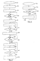
- Figure 4 shows the regulation flowchart of the pressure Pc which begins at step E3 of FIG. 3 by a step E14 during which the air actuator 4 is established at the value Da0.
- the regulation consists in maintain the position of the air actuator 4.
- the computer B performs the test E15.
- the computer controls the actuator 4 to a corresponding position Da1 to the air mass necessary for the engine idles (step E16).
- the computer B establishes an open-loop control of the pressure Pc, as a function of a setpoint equal to Pc0 and possibly other parameters such as engine speed A.
- the Pc0 value is preferably equal to the average value of pressure builds up at idle speed. She may be stored in a characteristic table accessible to calculator B and may itself vary depending on other parameters such as the setpoint speed of the idle temperature of the cooling water heat engine or other.
Landscapes
- Engineering & Computer Science (AREA)
- Chemical & Material Sciences (AREA)
- Combustion & Propulsion (AREA)
- Mechanical Engineering (AREA)
- General Engineering & Computer Science (AREA)
- Control Of Vehicle Engines Or Engines For Specific Uses (AREA)
- Electrical Control Of Air Or Fuel Supplied To Internal-Combustion Engine (AREA)
- Combined Controls Of Internal Combustion Engines (AREA)
Description
- à la suite d'un ordre de démarrage, à commander la machine électrique pour qu'elle délivre sa puissance totale disponible, à commander ledit organe de réglage de débit vers une-position de débit minimale et à positionner l'avance à l'allumage à une position minimale;
- pendant la rotation de ladite machine, à comparer le régime du moteur à combustion interne à un premier seuil de régime et à comparer la pression dans le collecteur d'admission à un premier seuil de pression de collecteur d'admission;
- à injecter du carburant dans les cylindres du moteur dès que les conditions conjuguées suivantes sont satisfaites: ledit premier seuil de régime est franchi vers le haut par ledit régime et ledit premier seuil de pression est franchi vers le bas par ladite pression de collecteur d'admission;
- à couper ladite machine électrique après écoulement d'un premier intervalle de temps prédéterminé suivant le début de l'injection de carburant dans le moteur; puis
- à réguler les paramètres de fonctionnement du moteur pour établir son régime de ralenti.
- ledit premier intervalle de temps présente une durée d'un nombre de temps moteurs prédéterminé, de préférence au moins égal à trois;
- l'opération d'établissement du régime de ralenti consiste:
- consécutivement à la coupure de ladite machine, à comparer ledit régime à un second seuil de régime supérieur audit premier seuil de régime, et au régime de ralenti du moteur et à comparer ladite pression de collecteur à un second seuil de pression inférieur au premier seuil de pression, et
- à augmenter l'avance à l'allumage à une valeur de ralenti, lorsque les deux conditions conjuguées suivantes sont satisfaites: ledit second seuil de régime est franchi vers le bas par ledit régime et ledit second seuil de pression est franchi vers le bas par ladite pression de collecteur d'admission;
- le procédé consiste également à étaler ladite augmentation de l'avance à l'allumage sur un nombre de temps moteur prédéterminé ;
- ladite opération d'établissement du régime de ralenti consiste également à comparer ladite pression du collecteur d'admission à un troisième seuil de pression inférieur auxdits premier et second seuils de pression et à commander ledit organe de réglage de débit vers une position de débit correspondant au ralenti du moteur, lorsque ladite pression de collecteur d'admission franchit ledit troisième seuil de pression vers le bas.
- la figure 1 est un schéma symbolique d'un dispositif de démarrage automatique d'un moteur à combustion interne, mettant en oeuvre le procédé selon l'invention;
- les figures 2a à 2f sont des diagrammes des temps illustrant le procédé de démarrage automatique selon l'invention;
- la figure 3 est un organigramme illustrant un exemple de procédé de démarrage automatique selon l'invention; et
- la figure 4 est un organigramme illustrant la régulation d'un paramètre de fonctionnement du moteur thermique pendant le processus de démarrage automatique.
Claims (5)
- Procédé de démarrage automatique d'un moteur à combustion interne à allumage commandé pour véhicule automobile qui pour son lancement peut être couplé à une machine électrique d'entraínement (10) et qui est alimenté en air par l'intermédiaire d'un collecteur d'admission (2) muni d'un organe (4) de réglage de débit d'air motorisé, ce procédé étant caractérisé en ce qu'il consiste:à la suite d'un ordre de démarrage, à commander la machine électrique (10) pour qu'elle délivre sa puissance totale disponible, à commander ledit organe (4) de réglage de débit vers une position de débit minimale et à positionner l'avance à l'allumage (6) à une position minimale;pendant la rotation de ladite machine (10), à comparer le régime (R) du moteur à combustion interne à un premier seuil de régime (R1) et à comparer la pression (Pc) dans le collecteur d'admission (2) à un premier seuil de pression de collecteur d'admission (Pc1);à injecter du carburant dans les cylindres (1) du moteur dès que les conditions conjuguées suivantes sont satisfaites: ledit premier seuil de régime (R1) est franchi vers le haut par ledit régime (R) et ledit premier seuil de pression (Pc1) est franchi vers le bas par ladite pression de collecteur d'admission (Pc);à couper ladite machine électrique (10) après écoulement d'un premier intervalle de temps (T1) prédéterminé suivant le début de l'injection de carburant dans le moteur; puisà réguler les paramètres de fonctionnement du moteur pour établir son régime de ralenti.
- Procédé suivant la revendication 1, caractérisé en ce que ledit premier intervalle de temps (T1) présente une durée d'un nombre de temps moteurs prédéterminé, de préférence au moins égal à trois.
- Procédé suivant l'une quelconque des revendications 1 et 2, caractérisé en ce que l'opération d'établissement du régime de ralenti consiste:consécutivement à la coupure de ladite machine (10), à comparer ledit régime (R) à un second seuil de régime (R2) supérieur audit premier seuil de régime (R1) au régime de ralenti (RR) du moteur et à comparer ladite pression de collecteur (Pc) à un second seuil de pression (Pc2) inférieur au premier seuil de pression (Pc1), età augmenter l'avance à l'allumage à une valeur de ralenti (AV2), lorsque les deux conditions conjuguées suivantes sont satisfaites: ledit second seuil de régime (R2) est franchi vers le bas par ledit régime et ledit second seuil de pression (Pc2) est franchi vers le bas par ladite pression de collecteur d'admission (Pc).
- Procédé suivant la revendication 3, caractérisé en ce qu'il consiste également à étaler ladite augmentation de l'avance à l'allumage sur un nombre de temps moteur (T) prédéterminé.
- Procédé suivant l'une quelconque des revendications 1 à 4, caractérisé en ce que ladite opération d'établissement du régime de ralenti consiste également à comparer ladite pression du collecteur d'admission (Pc) à un troisième seuil de pression (Pc0) inférieur auxdits premier et second seuils de pression (Pc1, Pc2) et à commander ledit organe de réglage de débit (4) vers une position de débit correspondant au ralenti du moteur, lorsque ladite pression de collecteur d'admission (Pc) franchit ledit troisième seuil de pression (Pc0) vers le bas.
Applications Claiming Priority (2)
| Application Number | Priority Date | Filing Date | Title |
|---|---|---|---|
| FR9910471A FR2797473B1 (fr) | 1999-08-13 | 1999-08-13 | Procede de demarrage d'un moteur a combustion interne a allumage commande |
| FR9910471 | 1999-08-13 |
Publications (2)
| Publication Number | Publication Date |
|---|---|
| EP1076177A1 EP1076177A1 (fr) | 2001-02-14 |
| EP1076177B1 true EP1076177B1 (fr) | 2004-11-24 |
Family
ID=9549127
Family Applications (1)
| Application Number | Title | Priority Date | Filing Date |
|---|---|---|---|
| EP20000402263 Expired - Lifetime EP1076177B1 (fr) | 1999-08-13 | 2000-08-10 | Procédé de démarrage d'un moteur à combustion interne à allumage commandé |
Country Status (4)
| Country | Link |
|---|---|
| EP (1) | EP1076177B1 (fr) |
| DE (1) | DE60016107T2 (fr) |
| ES (1) | ES2226742T3 (fr) |
| FR (1) | FR2797473B1 (fr) |
Families Citing this family (3)
| Publication number | Priority date | Publication date | Assignee | Title |
|---|---|---|---|---|
| DE602004007471T2 (de) * | 2004-02-20 | 2008-03-13 | Ford Global Technologies, LLC, Dearborn | Verfahren zur Verringerung des während des Anlassvorgang erzeugten Abgasschadstoffausstosses einer Brennkraftmaschine |
| FR3034468B1 (fr) | 2015-04-02 | 2017-04-21 | Peugeot Citroen Automobiles Sa | Procede de demarrage automatique d’un moteur a combustion interne a allumage commande |
| CN114320699A (zh) * | 2021-12-27 | 2022-04-12 | 联合汽车电子有限公司 | 车辆油路排气起动方法、装置及存储介质 |
Family Cites Families (5)
| Publication number | Priority date | Publication date | Assignee | Title |
|---|---|---|---|---|
| JPS6049235U (ja) * | 1983-09-12 | 1985-04-06 | 愛三工業株式会社 | 内燃機関のスロットル制御装置 |
| JP2539221B2 (ja) * | 1987-06-10 | 1996-10-02 | マツダ株式会社 | エンジンの始動充電装置 |
| JPH08193531A (ja) * | 1995-01-17 | 1996-07-30 | Nippondenso Co Ltd | ハイブリッド車両の制御システム |
| JP3610687B2 (ja) * | 1995-12-12 | 2005-01-19 | トヨタ自動車株式会社 | 内燃機関の始動制御装置およびその制御方法 |
| EP0947044B1 (fr) * | 1996-12-03 | 2003-05-07 | Elliott Energy Systems, Inc. | Systeme electrique de turboalternateur sur arbre commun |
-
1999
- 1999-08-13 FR FR9910471A patent/FR2797473B1/fr not_active Expired - Fee Related
-
2000
- 2000-08-10 DE DE2000616107 patent/DE60016107T2/de not_active Expired - Lifetime
- 2000-08-10 ES ES00402263T patent/ES2226742T3/es not_active Expired - Lifetime
- 2000-08-10 EP EP20000402263 patent/EP1076177B1/fr not_active Expired - Lifetime
Also Published As
| Publication number | Publication date |
|---|---|
| DE60016107T2 (de) | 2005-04-21 |
| DE60016107D1 (de) | 2004-12-30 |
| ES2226742T3 (es) | 2005-04-01 |
| FR2797473B1 (fr) | 2001-10-26 |
| FR2797473A1 (fr) | 2001-02-16 |
| EP1076177A1 (fr) | 2001-02-14 |
Similar Documents
| Publication | Publication Date | Title |
|---|---|---|
| FR2855215A1 (fr) | Procede de mise en oeuvre d'un moteur a combustion interne | |
| FR2851302A1 (fr) | Procede de gestion d'un moteur a combustion interne | |
| EP1454048A2 (fr) | Procede d'arret et de redemarrage d'un moteur a combustion inter ne a injection indirecte | |
| FR2823254A1 (fr) | Appareil de commande d'emission d'un moteur a combustion interne et procede pour retarder la deterioration du catalyseur de commande d'emission | |
| FR2906318A1 (fr) | Procede de demarrage d'un moteur a combustion interne et dispositif ainsi que programme pour sa mise en oeuvre. | |
| FR2875539A1 (fr) | Procede et dispositif de gestion d'un moteur a combustion interne equipe d'un catalyseur | |
| FR2568631A1 (fr) | Carburateur a dispositif de depart automatique | |
| FR3064683B1 (fr) | Procede de controle d'un moteur a allumage commande suralimente avec recirculation partielle des gaz d'echappement, et dispositif de motorisation associe | |
| FR2764559A1 (fr) | Systeme d'entrainement pour vehicule a moteur | |
| EP2806143A1 (fr) | Procédé d'arrêt d'un moteur thermique de véhicule automobile | |
| EP1076177B1 (fr) | Procédé de démarrage d'un moteur à combustion interne à allumage commandé | |
| FR2541728A1 (fr) | Procede de reglage du ralenti par reaction dans un moteur a combustion interne | |
| WO2016156699A1 (fr) | Procede de demarrage automatique d'un moteur a combustion interne a allumage commande | |
| FR2858666A1 (fr) | Procede de demarrage d'un moteur a combustion interne a plusieurs cylindres | |
| FR2838773A1 (fr) | Procede et appareil de commande et de regulation pour la gestion d'un moteur a combustion interne | |
| EP1084338B1 (fr) | Moteur a essence a quatre temps a allumage commande, a injection directe de carburant | |
| EP0565431B1 (fr) | Perfectionnements aux moteurs diesel | |
| WO1994024429A1 (fr) | Procede de commande d'un moteur a combustion interne lors d'une entree en regime de ralenti | |
| FR3072418A1 (fr) | Procede de controle d'un moteur a combustion interne a allumage commande, a l'etat non allume | |
| FR2791090A1 (fr) | Procede de commande d'un moteur a combustion interne | |
| FR2817293A1 (fr) | Procede et dispositif de commande de l'unite motrice d'un vehicule | |
| CN113195882B (zh) | 用于运行内燃机的方法及相应的内燃机 | |
| EP1074714A1 (fr) | Moteur turbocompressé perfectionné | |
| FR2784944A1 (fr) | Groupe motopropulseur hybride | |
| FR3020837A1 (fr) | Procede de gestion d'un moteur a combustion interne de vehicule automobile en mode de poussee pour reduire la consommation de carburant et les emissions |
Legal Events
| Date | Code | Title | Description |
|---|---|---|---|
| PUAI | Public reference made under article 153(3) epc to a published international application that has entered the european phase |
Free format text: ORIGINAL CODE: 0009012 |
|
| AK | Designated contracting states |
Kind code of ref document: A1 Designated state(s): DE ES GB IT |
|
| AX | Request for extension of the european patent |
Free format text: AL;LT;LV;MK;RO;SI |
|
| 17P | Request for examination filed |
Effective date: 20010730 |
|
| AKX | Designation fees paid |
Free format text: AT BE CH CY LI |
|
| RBV | Designated contracting states (corrected) |
Designated state(s): DE ES GB IT |
|
| RAP1 | Party data changed (applicant data changed or rights of an application transferred) |
Owner name: RENAULT S.A.S. |
|
| GRAP | Despatch of communication of intention to grant a patent |
Free format text: ORIGINAL CODE: EPIDOSNIGR1 |
|
| GRAS | Grant fee paid |
Free format text: ORIGINAL CODE: EPIDOSNIGR3 |
|
| GRAA | (expected) grant |
Free format text: ORIGINAL CODE: 0009210 |
|
| AK | Designated contracting states |
Kind code of ref document: B1 Designated state(s): DE ES GB IT |
|
| REG | Reference to a national code |
Ref country code: GB Ref legal event code: FG4D Free format text: NOT ENGLISH |
|
| REF | Corresponds to: |
Ref document number: 60016107 Country of ref document: DE Date of ref document: 20041230 Kind code of ref document: P |
|
| REG | Reference to a national code |
Ref country code: ES Ref legal event code: FG2A Ref document number: 2226742 Country of ref document: ES Kind code of ref document: T3 |
|
| GBT | Gb: translation of ep patent filed (gb section 77(6)(a)/1977) |
Effective date: 20050519 |
|
| PLBE | No opposition filed within time limit |
Free format text: ORIGINAL CODE: 0009261 |
|
| STAA | Information on the status of an ep patent application or granted ep patent |
Free format text: STATUS: NO OPPOSITION FILED WITHIN TIME LIMIT |
|
| 26N | No opposition filed |
Effective date: 20050825 |
|
| PGFP | Annual fee paid to national office [announced via postgrant information from national office to epo] |
Ref country code: GB Payment date: 20150819 Year of fee payment: 16 Ref country code: DE Payment date: 20150821 Year of fee payment: 16 Ref country code: ES Payment date: 20150827 Year of fee payment: 16 |
|
| PGFP | Annual fee paid to national office [announced via postgrant information from national office to epo] |
Ref country code: IT Payment date: 20150824 Year of fee payment: 16 |
|
| REG | Reference to a national code |
Ref country code: DE Ref legal event code: R119 Ref document number: 60016107 Country of ref document: DE |
|
| GBPC | Gb: european patent ceased through non-payment of renewal fee |
Effective date: 20160810 |
|
| PG25 | Lapsed in a contracting state [announced via postgrant information from national office to epo] |
Ref country code: DE Free format text: LAPSE BECAUSE OF NON-PAYMENT OF DUE FEES Effective date: 20170301 Ref country code: GB Free format text: LAPSE BECAUSE OF NON-PAYMENT OF DUE FEES Effective date: 20160810 |
|
| PG25 | Lapsed in a contracting state [announced via postgrant information from national office to epo] |
Ref country code: IT Free format text: LAPSE BECAUSE OF NON-PAYMENT OF DUE FEES Effective date: 20160810 |
|
| PG25 | Lapsed in a contracting state [announced via postgrant information from national office to epo] |
Ref country code: ES Free format text: LAPSE BECAUSE OF NON-PAYMENT OF DUE FEES Effective date: 20160811 |
|
| REG | Reference to a national code |
Ref country code: ES Ref legal event code: FD2A Effective date: 20181123 |