EP1076189A2 - Dämpfer von variabler Federsteifigkeit, mit viskoser Flüssigkeit gefüllt - Google Patents
Dämpfer von variabler Federsteifigkeit, mit viskoser Flüssigkeit gefüllt Download PDFInfo
- Publication number
- EP1076189A2 EP1076189A2 EP00306759A EP00306759A EP1076189A2 EP 1076189 A2 EP1076189 A2 EP 1076189A2 EP 00306759 A EP00306759 A EP 00306759A EP 00306759 A EP00306759 A EP 00306759A EP 1076189 A2 EP1076189 A2 EP 1076189A2
- Authority
- EP
- European Patent Office
- Prior art keywords
- wall thickness
- spring constant
- type damper
- viscous fluid
- variable spring
- Prior art date
- Legal status (The legal status is an assumption and is not a legal conclusion. Google has not performed a legal analysis and makes no representation as to the accuracy of the status listed.)
- Granted
Links
Images



Classifications
-
- F—MECHANICAL ENGINEERING; LIGHTING; HEATING; WEAPONS; BLASTING
- F16—ENGINEERING ELEMENTS AND UNITS; GENERAL MEASURES FOR PRODUCING AND MAINTAINING EFFECTIVE FUNCTIONING OF MACHINES OR INSTALLATIONS; THERMAL INSULATION IN GENERAL
- F16F—SPRINGS; SHOCK-ABSORBERS; MEANS FOR DAMPING VIBRATION
- F16F13/00—Units comprising springs of the non-fluid type as well as vibration-dampers, shock-absorbers, or fluid springs
- F16F13/04—Units comprising springs of the non-fluid type as well as vibration-dampers, shock-absorbers, or fluid springs comprising both a plastics spring and a damper, e.g. a friction damper
- F16F13/06—Units comprising springs of the non-fluid type as well as vibration-dampers, shock-absorbers, or fluid springs comprising both a plastics spring and a damper, e.g. a friction damper the damper being a fluid damper, e.g. the plastics spring not forming a part of the wall of the fluid chamber of the damper
- F16F13/08—Units comprising springs of the non-fluid type as well as vibration-dampers, shock-absorbers, or fluid springs comprising both a plastics spring and a damper, e.g. a friction damper the damper being a fluid damper, e.g. the plastics spring not forming a part of the wall of the fluid chamber of the damper the plastics spring forming at least a part of the wall of the fluid chamber of the damper
- F16F13/10—Units comprising springs of the non-fluid type as well as vibration-dampers, shock-absorbers, or fluid springs comprising both a plastics spring and a damper, e.g. a friction damper the damper being a fluid damper, e.g. the plastics spring not forming a part of the wall of the fluid chamber of the damper the plastics spring forming at least a part of the wall of the fluid chamber of the damper the wall being at least in part formed by a flexible membrane or the like
- F16F13/108—Units comprising springs of the non-fluid type as well as vibration-dampers, shock-absorbers, or fluid springs comprising both a plastics spring and a damper, e.g. a friction damper the damper being a fluid damper, e.g. the plastics spring not forming a part of the wall of the fluid chamber of the damper the plastics spring forming at least a part of the wall of the fluid chamber of the damper the wall being at least in part formed by a flexible membrane or the like characterised by features of plastics springs, e.g. attachment arrangements
-
- F—MECHANICAL ENGINEERING; LIGHTING; HEATING; WEAPONS; BLASTING
- F16—ENGINEERING ELEMENTS AND UNITS; GENERAL MEASURES FOR PRODUCING AND MAINTAINING EFFECTIVE FUNCTIONING OF MACHINES OR INSTALLATIONS; THERMAL INSULATION IN GENERAL
- F16F—SPRINGS; SHOCK-ABSORBERS; MEANS FOR DAMPING VIBRATION
- F16F9/00—Springs, vibration-dampers, shock-absorbers, or similarly-constructed movement-dampers using a fluid or the equivalent as damping medium
- F16F9/10—Springs, vibration-dampers, shock-absorbers, or similarly-constructed movement-dampers using a fluid or the equivalent as damping medium using liquid only; using a fluid of which the nature is immaterial
- F16F9/103—Devices with one or more members moving linearly to and fro in chambers, any throttling effect being immaterial, i.e. damping by viscous shear effect only
Definitions
- This invention relates to a variable spring constant type damper filled with viscous fluid which is vibration isolator for damping a vibration from the external in acoustic instruments and information instruments using an optical disk or the like.
- a vibration effect is adjusted by changing the viscosity of the fluid of the viscous fluid sealed-type damper and the hardness of the elastic body like rubber of the supported body, for such various vibrations with consideration of a weight and a balance of the supported body.
- the apparent dynamic spring constant becomes high when sealing the high-viscosity fluid in the case of adjusting a vibration-isolating effect by the viscosity of the fluid, and its amplitude can be reduced by a high resonance frequency and a high damping force.
- the resonance frequency and the damping force are high for a high frequency of 100 Hz or more, whereby a reduction effect of a vibration transmissibility is low, that is to say, the vibration-isolating effect is reduced.
- the spring constant is small in a high-frequency band small in amplitude, the vibration transmissibility can be suppressed lower, and the spring constant is large in a low-frequency band large in amplitude, whereby a resonance magnification can be suppressed lower.
- variable spring constant type damper filled with viscous fluid which the flexible portion can not be broken in practical use, and which is large in securing strength between the flexible portion and the cylindrical portion and has high reliability is provided.
- this invention provides a variable spring constant type damper filled with viscous fluid in which the viscous fluid is sealed by the container constituted by the stirring portion, the cylindrical portion and the flexible portion made of the elastic body like rubber connecting the both portions and the cap_and the vibration damping is performed with the viscous resistance caused by the travelling of the stirring portion in the viscous fluid in response to the vibration from the external, in which the wall thickness of the flexible portion is varied.
- this invention provides a variable spring constant type damper filled with viscous fluid in which the wall thickness of the flexible portion has a step toward the cylindrical portion and its change is formed such that the thickness can be switched.
- the flexible portion is formed such that the periphery of the connection of the stirring portion and the cylindrical portion has the same wall thickness as that.
- the wall thickness of the flexible portion is formed so as to form the thin-walled portion and the thick-walled portion in the circumferential direction toward the cylindrical portion from the stirring portion radially alternately.
- the ratio of the thin wall thickness versus the thick wall thickness of the flexible portion is set at 1.0 :1.1 to 1.0 : 5.0.
- the ratio of the thin wall thickness versus the thick wall thickness of the flexible portion depends upon the size of the damper and the strength of the elastic body like rubber or the like, it is preferably within the range of 1.0 : 1.1 ⁇ 1.0 : 5.0.
- the change in the thickness does not appear on the change in the spring constant as the damper, when the wall thickness of the thick walled portion with respective to the wall thickness of 1.0 of the thin-walled portion is smaller than 1.1, on the one hand, the difference in tensile stress strength of the thin-walled portion and the thick-walled portion appears remarkably, when being larger than 5.0, and only the thin-walled portion can oscillate even though the amplitude becomes large, whereby it does not appear on the change in the spring constant.
- the ratio of the wall thickness is preferably within the range of 1.0 :1.5 ⁇ 1.0 : 3.0.
- the wall thickness on a circumference of a concentric circle is formed equally outwardly from the flexible portion, and since the wall thickness in the thin-walled portion is thin, the spring constant is small, moreover, since the wall thickness in the thick-walled portion is thick, the spring constant is large.
- any one thereof may be arranged on the inner periphery side, moreover, for a manner of the change in the thickness, either of the change which varies successively or in stages or the change which has the boundary and the thickness is switched may be permitted.
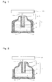
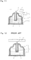
- Fig. 1 is a sectional view of a variable spring constant type damper filled with viscous fluid according to the invention.
- Fig. 2 is a sectional view of a variable spring constant type damper filled with viscous fluid according to the invention.
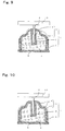
- Fig. 8 is a sectional view along line AA in Fig. 7.
- a portion approached toward the stirring portion 3 is formed with the thick-walled portion 7, on the one hand, a portion approached toward the cylindrical portion 8 side is formed with the thin-walled portion 6.
- the thick-walled portion 7 is formed on the flexible portion 9, and the periphery of the connection of the stirring portion 3 and the cylindrical portion 8 and the thin-walled portion 6 is formed on an intermediate portion thereof. According to the constitution shown in Fig. 6, vibration durability is improved while suppressing reduction of the vibration-isolating effect by thickening the wall thickness in the periphery of the connection between the stirring portion 3 and that most exerting an influence upon vibration durability.
- the thick-walled portion 7 and the thin-walled portion 6 in the flexible portion 9 are formed in the circumferential direction radially alternately.
- This cross-section shape along line A-A in Fig. 7 which the thick-walled portion 7 and the thin-walled portion 6 in the flexible portion 9 are formed in the circumferential direction radially alternately is shown in Fig. 8 (a) to (c).
- the cross-section shape can not be limited to the shape shown in Fig. 8, moreover, the wall thickness and the distance and the number of repetition which the wall thickness is varied also can not be limited.
- the thick-walled portion 7 and the thin-walled portion 6 in the flexible portion 9 are alternately formed in the circumferential direction radially.
- the periphery of the connection between the stirring portion 3 in the flexible portion 9 and that is formed with the thin-walled portion 6, and the thick-walled portion 7 and the thin-walled portion 6 are formed in the circumferential direction radially alternately toward the cylindrical portion 8.
- the periphery of the connection between the stirring portion 3 and the cylindrical portion 8 in the flexible portion 9 is formed with the thick-walled portion 7 and the thin-walled portion 6 and the thick-walled portion 7, are formed in the circumferential direction radially alternately at the intermediate portion thereof.
- the flexible portion 9 having the desired spring constant can be obtained more readily than adjusting the consistent wall thickness by an extremely minuscule amount by correcting the ratio of the thickness of the radial thick-walled portion 7, and the thin-walled portion 6.
- cylindrical portion 8 of the invention materials with rigidity are preferable and rigid resins, metal or the like are given.
- the elastic body like rubber is preferable and is selected from the well-known synthetic rubbers, and thermoplastic elastomer.
- synthetic rubbers styrene-butadiene rubber, butadiene rubber, chloroprene rubber, nitrile-butadiene rubber, butyl rubber, ethylene-propylene rubber, urethane rubber, silicone rubber, fluorine rubber, acrylic rubber or the like are given, and in the thermoplastic elastomer, a styrene system, a olefin system, an urethane system, an ester system, a vinyl chloride system or the like are given.
- thermoplastic rigid resin is used in the cylindrical portion and the thermoplastic elastomer is used in the flexible portion, dichroic molding by heat-fusion welding becomes possible.
- the cap 5 according to the invention may be either of a unitary material of the materials with rigidity or the elastic body like rubber, or the complex material by the combination of the both.
- the wall thickness of the thin-walled portion 6 constituting the flexible portion 9 was 0.25 mm
- the wall thickness of the thick-walled portion 7 was 0.5 mm
- the thin-walled portion 6 was provided on the periphery of the stirring portion 3
- the thick-walled portion 8 was provided on the outer periphery of the thin-walled portion 6.
- the wall thickness of the thin-walled portion 6 constituting the flexible portion 9 was 0.25 mm
- the wall thickness of the thick-walled portion 7 was 0.5 mm
- the thick-walled portion 7 was provided on the periphery of the stirring portion 3, furthermore, the thin-walled portion 6 was provided on the outer periphery of the thick-walled portion 7, thereby to obtain the variable spring constant type damper filled with viscous fluid of the embodiment 4 which has the same constitution as the embodiment 1 as a matter of the fact.
- the wall thickness of the thin-walled portion 6 constituting the flexible portion 9 was 0.25 mm
- the wall thickness of the thick-walled portion 7 was 0.38 mm
- the thick-walled portion 7 was provided on the periphery of the stirring portion 3, furthermore, the thin-walled portion 6 was provided on the outer periphery of the thick-walled portion 7, thereby to obtain the variable spring constant type damper filled with viscous fluid of the embodiment 5 which has the same constitution as the embodiment 1 as a matter of the fact.
- the wall thickness of the thin-walled portion 6 constituting the flexible portion 9 was 0.25 mm
- the wall thickness of the thick-walled portion 7 was 0.75 mm
- the thick-walled portion 7 was provided on the periphery of the stirring portion 3, furthermore, the thin-walled portion 6 was provided on the outer periphery of the thick-walled portion 7, thereby to obtain the variable spring constant type damper filled with viscous fluid of the embodiment 6 which has the same constitution as the embodiment 1 as a matter of the fact.
- the wall thickness of the thick-walled portion 7 was 0.8 mm, and the others were constituted in the same manner as the embodiment 7.
- silicone grease of the viscosity of 1.2 m 2 /s, measured by the rotational viscometer was used.
- the wall thickness of the thin-walled portion 6 constituting the flexible portion 9 was 0.2 mm
- the wall thickness of the thick-walled portion 7 was 0.4 mm
- the thickness of the flexible portion 9 was retained in the constant thickness of 0.3 mm.
- the others were constituted in the same manner as the embodiment 1, thereby to obtain the viscous fluid sealed-type damper of the comparative example 2.
Landscapes
- Engineering & Computer Science (AREA)
- General Engineering & Computer Science (AREA)
- Mechanical Engineering (AREA)
- Combined Devices Of Dampers And Springs (AREA)
Applications Claiming Priority (4)
| Application Number | Priority Date | Filing Date | Title |
|---|---|---|---|
| JP22602699A JP3987242B2 (ja) | 1999-08-10 | 1999-08-10 | バネ定数可変型粘性流体封入式ダンパー |
| JP22602699 | 1999-08-10 | ||
| JP2000086476 | 2000-03-27 | ||
| JP2000086476A JP2001271867A (ja) | 2000-03-27 | 2000-03-27 | バネ定数可変型粘性流体封入式ダンパー |
Publications (3)
| Publication Number | Publication Date |
|---|---|
| EP1076189A2 true EP1076189A2 (de) | 2001-02-14 |
| EP1076189A3 EP1076189A3 (de) | 2002-01-30 |
| EP1076189B1 EP1076189B1 (de) | 2004-12-29 |
Family
ID=26526950
Family Applications (1)
| Application Number | Title | Priority Date | Filing Date |
|---|---|---|---|
| EP00306759A Expired - Lifetime EP1076189B1 (de) | 1999-08-10 | 2000-08-08 | Dämpfer von variabler Federsteifigkeit, mit viskoser Flüssigkeit gefüllt |
Country Status (3)
| Country | Link |
|---|---|
| US (1) | US6439551B1 (de) |
| EP (1) | EP1076189B1 (de) |
| DE (1) | DE60017030T2 (de) |
Cited By (4)
| Publication number | Priority date | Publication date | Assignee | Title |
|---|---|---|---|---|
| EP1450068A3 (de) * | 2003-02-21 | 2004-09-22 | Firma Carl Freudenberg | Hydrolager |
| GB2423495A (en) * | 2005-02-24 | 2006-08-30 | Black & Decker Inc | Vibration damping handle assembly for hammer |
| EP1852870A1 (de) * | 2006-05-02 | 2007-11-07 | Polymatech Co., Ltd. | Viskose Flüssigkeit enthaltender Dämpfer |
| CN101295533B (zh) * | 2007-04-24 | 2010-12-08 | 蒂雅克股份有限公司 | 光盘装置 |
Families Citing this family (9)
| Publication number | Priority date | Publication date | Assignee | Title |
|---|---|---|---|---|
| DE19838753A1 (de) * | 1998-08-26 | 2000-03-02 | Philips Corp Intellectual Pty | Flüssigkeitsgefüllter Dämpfer für ein erschütterungsempfindliches Gerät und Verfahren zu dessen Herstellung |
| JP4347515B2 (ja) * | 2000-11-27 | 2009-10-21 | ポリマテック株式会社 | 防振ダンパー一体型メカニカルシャーシ |
| JP4240923B2 (ja) * | 2001-12-14 | 2009-03-18 | ポリマテック株式会社 | ダンパーおよびメカシャーシの防振構造 |
| WO2006037096A2 (en) * | 2004-09-28 | 2006-04-06 | Cooper-Standard Automotive Inc. | One-piece outer split shell pre-compressed cradle/sub-frame mount |
| JP4738083B2 (ja) * | 2005-07-27 | 2011-08-03 | ポリマテック株式会社 | 粘性流体封入ダンパーおよび粘性流体封入ダンパーの取付構造 |
| JP4908798B2 (ja) * | 2005-08-05 | 2012-04-04 | ポリマテック株式会社 | 粘性流体封入ダンパー |
| JP2007113622A (ja) * | 2005-10-19 | 2007-05-10 | Tanashin Denki Co | オイルダンパ |
| GB2486499A (en) * | 2010-12-17 | 2012-06-20 | Perkinelmer Ltd | Anti-vibration foot portions for spectroscopic instruments |
| WO2012142103A2 (en) * | 2011-04-11 | 2012-10-18 | Trelleborg Automotive Usa, Inc. | Method of producing split outer shell cradle mount with rate plates |
Family Cites Families (8)
| Publication number | Priority date | Publication date | Assignee | Title |
|---|---|---|---|---|
| JPH0249038Y2 (de) * | 1984-10-11 | 1990-12-21 | ||
| JPH0384240A (ja) * | 1989-08-23 | 1991-04-09 | Tokai Rubber Ind Ltd | 液体封入ダンパーの製造方法 |
| GB2241042B (en) * | 1990-02-16 | 1994-01-05 | Pioneer Electronic Corp | Damper filled with oil |
| JP3053031B2 (ja) * | 1991-10-29 | 2000-06-19 | 三菱電機株式会社 | 防振装置 |
| JPH06119770A (ja) * | 1992-08-18 | 1994-04-28 | Sony Corp | 防振機構 |
| US5624104A (en) * | 1994-11-23 | 1997-04-29 | Nippon Steel Corporation | Vibration isolating supporter |
| JPH08177945A (ja) * | 1994-12-21 | 1996-07-12 | Tokai Rubber Ind Ltd | 流体封入式筒型防振装置 |
| JPH10188547A (ja) * | 1996-12-20 | 1998-07-21 | Sony Corp | ダンパ |
-
2000
- 2000-07-31 US US09/629,811 patent/US6439551B1/en not_active Expired - Fee Related
- 2000-08-08 EP EP00306759A patent/EP1076189B1/de not_active Expired - Lifetime
- 2000-08-08 DE DE60017030T patent/DE60017030T2/de not_active Expired - Lifetime
Cited By (4)
| Publication number | Priority date | Publication date | Assignee | Title |
|---|---|---|---|---|
| EP1450068A3 (de) * | 2003-02-21 | 2004-09-22 | Firma Carl Freudenberg | Hydrolager |
| GB2423495A (en) * | 2005-02-24 | 2006-08-30 | Black & Decker Inc | Vibration damping handle assembly for hammer |
| EP1852870A1 (de) * | 2006-05-02 | 2007-11-07 | Polymatech Co., Ltd. | Viskose Flüssigkeit enthaltender Dämpfer |
| CN101295533B (zh) * | 2007-04-24 | 2010-12-08 | 蒂雅克股份有限公司 | 光盘装置 |
Also Published As
| Publication number | Publication date |
|---|---|
| DE60017030D1 (de) | 2005-02-03 |
| DE60017030T2 (de) | 2005-12-15 |
| US6439551B1 (en) | 2002-08-27 |
| EP1076189B1 (de) | 2004-12-29 |
| EP1076189A3 (de) | 2002-01-30 |
Similar Documents
| Publication | Publication Date | Title |
|---|---|---|
| EP1076189B1 (de) | Dämpfer von variabler Federsteifigkeit, mit viskoser Flüssigkeit gefüllt | |
| US6981696B2 (en) | Fluid-filled cylindrical vibration damping device | |
| US6554112B2 (en) | Vibration-damping device for vehicle | |
| JP3035334B2 (ja) | ばね架装台 | |
| EP2025968B1 (de) | Schwingungsdämpfungsvorrichtung | |
| JP3772715B2 (ja) | 制振装置 | |
| EP0332150B1 (de) | Flüssigkeitsgefüllte Buchsenfeder mit einem beweglichen Glied in der Flüssigkeitskammer | |
| JPWO2007116976A1 (ja) | 防振装置 | |
| EP0326504A2 (de) | Buchsenartiges hydraulisch gedämpftes Motor- oder Getriebelager | |
| JP2000186739A (ja) | 流体封入式防振装置 | |
| US5213313A (en) | Fluid-filled cylindrical elastic mount having lateral and radial elastic walls for desired axial and diametric spring characteristics | |
| JPS591831A (ja) | 緩衝支持体 | |
| JP4134756B2 (ja) | 液封エンジンマウント装置におけるゴムストッパ | |
| JP4636441B2 (ja) | 筒形ダイナミックダンパ | |
| US5009403A (en) | Fluid-filled elastic mount | |
| JP2006132615A (ja) | 防振装置 | |
| JP4718137B2 (ja) | 防振装置 | |
| JP4976056B2 (ja) | 防振装置 | |
| US20040188902A1 (en) | Fluid-filled vibration damping mount | |
| JP3987242B2 (ja) | バネ定数可変型粘性流体封入式ダンパー | |
| EP0385463A1 (de) | Oberes Lager für Stossdämpfer in einem Aufhängungssystem | |
| JP4275340B2 (ja) | 防振装置 | |
| JP2001271867A (ja) | バネ定数可変型粘性流体封入式ダンパー | |
| JP2000065120A (ja) | 減衰可変型粘性流体封入式ダンパー | |
| JPH10267069A (ja) | 防振装置 |
Legal Events
| Date | Code | Title | Description |
|---|---|---|---|
| PUAI | Public reference made under article 153(3) epc to a published international application that has entered the european phase |
Free format text: ORIGINAL CODE: 0009012 |
|
| AK | Designated contracting states |
Kind code of ref document: A2 Designated state(s): DE GB NL Kind code of ref document: A2 Designated state(s): AT BE CH CY DE DK ES FI FR GB GR IE IT LI LU MC NL PT SE |
|
| AX | Request for extension of the european patent |
Free format text: AL;LT;LV;MK;RO;SI |
|
| PUAL | Search report despatched |
Free format text: ORIGINAL CODE: 0009013 |
|
| AK | Designated contracting states |
Kind code of ref document: A3 Designated state(s): AT BE CH CY DE DK ES FI FR GB GR IE IT LI LU MC NL PT SE |
|
| AX | Request for extension of the european patent |
Free format text: AL;LT;LV;MK;RO;SI |
|
| RIC1 | Information provided on ipc code assigned before grant |
Free format text: 7F 16F 9/10 A, 7F 16F 13/10 B |
|
| 17P | Request for examination filed |
Effective date: 20020415 |
|
| AKX | Designation fees paid |
Free format text: DE GB NL |
|
| GRAP | Despatch of communication of intention to grant a patent |
Free format text: ORIGINAL CODE: EPIDOSNIGR1 |
|
| RAP1 | Party data changed (applicant data changed or rights of an application transferred) |
Owner name: POLYMATECH CO., LTD. |
|
| GRAS | Grant fee paid |
Free format text: ORIGINAL CODE: EPIDOSNIGR3 |
|
| GRAA | (expected) grant |
Free format text: ORIGINAL CODE: 0009210 |
|
| AK | Designated contracting states |
Kind code of ref document: B1 Designated state(s): DE GB NL |
|
| REG | Reference to a national code |
Ref country code: GB Ref legal event code: FG4D |
|
| REG | Reference to a national code |
Ref country code: IE Ref legal event code: FG4D |
|
| REF | Corresponds to: |
Ref document number: 60017030 Country of ref document: DE Date of ref document: 20050203 Kind code of ref document: P |
|
| PLBE | No opposition filed within time limit |
Free format text: ORIGINAL CODE: 0009261 |
|
| STAA | Information on the status of an ep patent application or granted ep patent |
Free format text: STATUS: NO OPPOSITION FILED WITHIN TIME LIMIT |
|
| 26N | No opposition filed |
Effective date: 20050930 |
|
| PGFP | Annual fee paid to national office [announced via postgrant information from national office to epo] |
Ref country code: DE Payment date: 20090806 Year of fee payment: 10 Ref country code: GB Payment date: 20090805 Year of fee payment: 10 Ref country code: NL Payment date: 20090803 Year of fee payment: 10 |
|
| REG | Reference to a national code |
Ref country code: NL Ref legal event code: V1 Effective date: 20110301 |
|
| GBPC | Gb: european patent ceased through non-payment of renewal fee |
Effective date: 20100808 |
|
| PG25 | Lapsed in a contracting state [announced via postgrant information from national office to epo] |
Ref country code: NL Free format text: LAPSE BECAUSE OF NON-PAYMENT OF DUE FEES Effective date: 20110301 |
|
| REG | Reference to a national code |
Ref country code: DE Ref legal event code: R119 Ref document number: 60017030 Country of ref document: DE Effective date: 20110301 |
|
| PG25 | Lapsed in a contracting state [announced via postgrant information from national office to epo] |
Ref country code: DE Free format text: LAPSE BECAUSE OF NON-PAYMENT OF DUE FEES Effective date: 20110301 |
|
| PG25 | Lapsed in a contracting state [announced via postgrant information from national office to epo] |
Ref country code: GB Free format text: LAPSE BECAUSE OF NON-PAYMENT OF DUE FEES Effective date: 20100808 |