EP1076350A2 - Druck- und temperaturempfindlicher Schalter - Google Patents
Druck- und temperaturempfindlicher Schalter Download PDFInfo
- Publication number
- EP1076350A2 EP1076350A2 EP00306742A EP00306742A EP1076350A2 EP 1076350 A2 EP1076350 A2 EP 1076350A2 EP 00306742 A EP00306742 A EP 00306742A EP 00306742 A EP00306742 A EP 00306742A EP 1076350 A2 EP1076350 A2 EP 1076350A2
- Authority
- EP
- European Patent Office
- Prior art keywords
- switch
- diaphragm
- fixed contact
- responsive
- bumper
- Prior art date
- Legal status (The legal status is an assumption and is not a legal conclusion. Google has not performed a legal analysis and makes no representation as to the accuracy of the status listed.)
- Withdrawn
Links
- 239000011888 foil Substances 0.000 claims abstract description 65
- 230000004044 response Effects 0.000 claims abstract description 31
- 239000000463 material Substances 0.000 claims abstract description 15
- 229910001285 shape-memory alloy Inorganic materials 0.000 claims abstract description 14
- 229910052751 metal Inorganic materials 0.000 claims description 70
- 239000002184 metal Substances 0.000 claims description 70
- 239000012212 insulator Substances 0.000 claims description 36
- 230000002093 peripheral effect Effects 0.000 claims description 30
- 239000004020 conductor Substances 0.000 claims description 15
- 239000011810 insulating material Substances 0.000 claims description 5
- 238000005452 bending Methods 0.000 claims description 2
- 241000719190 Chloroscombrus Species 0.000 description 28
- 239000012530 fluid Substances 0.000 description 8
- 230000009466 transformation Effects 0.000 description 8
- 229910052782 aluminium Inorganic materials 0.000 description 5
- XAGFODPZIPBFFR-UHFFFAOYSA-N aluminium Chemical compound [Al] XAGFODPZIPBFFR-UHFFFAOYSA-N 0.000 description 5
- 238000001816 cooling Methods 0.000 description 5
- 238000007747 plating Methods 0.000 description 5
- PXHVJJICTQNCMI-UHFFFAOYSA-N Nickel Chemical compound [Ni] PXHVJJICTQNCMI-UHFFFAOYSA-N 0.000 description 4
- 239000010970 precious metal Substances 0.000 description 4
- 239000012781 shape memory material Substances 0.000 description 4
- BQCADISMDOOEFD-UHFFFAOYSA-N Silver Chemical compound [Ag] BQCADISMDOOEFD-UHFFFAOYSA-N 0.000 description 3
- 230000009471 action Effects 0.000 description 3
- 238000007599 discharging Methods 0.000 description 3
- 238000010292 electrical insulation Methods 0.000 description 3
- 239000003792 electrolyte Substances 0.000 description 3
- 230000006870 function Effects 0.000 description 3
- 238000010438 heat treatment Methods 0.000 description 3
- 229910052709 silver Inorganic materials 0.000 description 3
- 239000004332 silver Substances 0.000 description 3
- 230000007704 transition Effects 0.000 description 3
- HZEWFHLRYVTOIW-UHFFFAOYSA-N [Ti].[Ni] Chemical compound [Ti].[Ni] HZEWFHLRYVTOIW-UHFFFAOYSA-N 0.000 description 2
- 229910045601 alloy Inorganic materials 0.000 description 2
- 239000000956 alloy Substances 0.000 description 2
- 230000004075 alteration Effects 0.000 description 2
- 239000010405 anode material Substances 0.000 description 2
- 239000010406 cathode material Substances 0.000 description 2
- 230000008859 change Effects 0.000 description 2
- -1 copper-zinc-aluminum Chemical compound 0.000 description 2
- PCHJSUWPFVWCPO-UHFFFAOYSA-N gold Chemical compound [Au] PCHJSUWPFVWCPO-UHFFFAOYSA-N 0.000 description 2
- 229910052737 gold Inorganic materials 0.000 description 2
- 239000010931 gold Substances 0.000 description 2
- 230000006872 improvement Effects 0.000 description 2
- 230000004048 modification Effects 0.000 description 2
- 238000012986 modification Methods 0.000 description 2
- 229910052759 nickel Inorganic materials 0.000 description 2
- 229910001000 nickel titanium Inorganic materials 0.000 description 2
- 239000000615 nonconductor Substances 0.000 description 2
- 230000000153 supplemental effect Effects 0.000 description 2
- 238000013022 venting Methods 0.000 description 2
- 229910001369 Brass Inorganic materials 0.000 description 1
- RYGMFSIKBFXOCR-UHFFFAOYSA-N Copper Chemical compound [Cu] RYGMFSIKBFXOCR-UHFFFAOYSA-N 0.000 description 1
- 229910000831 Steel Inorganic materials 0.000 description 1
- 238000000429 assembly Methods 0.000 description 1
- 230000000712 assembly Effects 0.000 description 1
- 230000015572 biosynthetic process Effects 0.000 description 1
- 239000010951 brass Substances 0.000 description 1
- 239000011248 coating agent Substances 0.000 description 1
- 238000000576 coating method Methods 0.000 description 1
- 239000010960 cold rolled steel Substances 0.000 description 1
- 230000006835 compression Effects 0.000 description 1
- 238000007906 compression Methods 0.000 description 1
- 238000010276 construction Methods 0.000 description 1
- 229910052802 copper Inorganic materials 0.000 description 1
- 239000010949 copper Substances 0.000 description 1
- 238000005520 cutting process Methods 0.000 description 1
- 238000009713 electroplating Methods 0.000 description 1
- 235000015110 jellies Nutrition 0.000 description 1
- 239000008274 jelly Substances 0.000 description 1
- 239000007788 liquid Substances 0.000 description 1
- 238000004519 manufacturing process Methods 0.000 description 1
- 229910000734 martensite Inorganic materials 0.000 description 1
- 238000000034 method Methods 0.000 description 1
- 239000000203 mixture Substances 0.000 description 1
- 230000008569 process Effects 0.000 description 1
- 230000006903 response to temperature Effects 0.000 description 1
- 239000002904 solvent Substances 0.000 description 1
- 238000004544 sputter deposition Methods 0.000 description 1
- 239000010959 steel Substances 0.000 description 1
- 238000007740 vapor deposition Methods 0.000 description 1
Images



Classifications
-
- H—ELECTRICITY
- H01—ELECTRIC ELEMENTS
- H01H—ELECTRIC SWITCHES; RELAYS; SELECTORS; EMERGENCY PROTECTIVE DEVICES
- H01H37/00—Thermally-actuated switches
- H01H37/02—Details
- H01H37/32—Thermally-sensitive members
- H01H37/52—Thermally-sensitive members actuated due to deflection of bimetallic element
-
- H—ELECTRICITY
- H01—ELECTRIC ELEMENTS
- H01H—ELECTRIC SWITCHES; RELAYS; SELECTORS; EMERGENCY PROTECTIVE DEVICES
- H01H35/00—Switches operated by change of a physical condition
-
- H—ELECTRICITY
- H01—ELECTRIC ELEMENTS
- H01H—ELECTRIC SWITCHES; RELAYS; SELECTORS; EMERGENCY PROTECTIVE DEVICES
- H01H35/00—Switches operated by change of a physical condition
- H01H35/24—Switches operated by change of fluid pressure, by fluid pressure waves, or by change of fluid flow
- H01H35/34—Switches operated by change of fluid pressure, by fluid pressure waves, or by change of fluid flow actuated by diaphragm
- H01H35/343—Switches operated by change of fluid pressure, by fluid pressure waves, or by change of fluid flow actuated by diaphragm by snap acting diaphragm
-
- H—ELECTRICITY
- H01—ELECTRIC ELEMENTS
- H01H—ELECTRIC SWITCHES; RELAYS; SELECTORS; EMERGENCY PROTECTIVE DEVICES
- H01H37/00—Thermally-actuated switches
- H01H37/02—Details
- H01H37/32—Thermally-sensitive members
- H01H37/323—Thermally-sensitive members making use of shape memory materials
-
- H—ELECTRICITY
- H01—ELECTRIC ELEMENTS
- H01H—ELECTRIC SWITCHES; RELAYS; SELECTORS; EMERGENCY PROTECTIVE DEVICES
- H01H37/00—Thermally-actuated switches
- H01H37/02—Details
- H01H37/32—Thermally-sensitive members
- H01H37/52—Thermally-sensitive members actuated due to deflection of bimetallic element
- H01H37/54—Thermally-sensitive members actuated due to deflection of bimetallic element wherein the bimetallic element is inherently snap acting
- H01H2037/5463—Thermally-sensitive members actuated due to deflection of bimetallic element wherein the bimetallic element is inherently snap acting the bimetallic snap element forming part of switched circuit
-
- H—ELECTRICITY
- H01—ELECTRIC ELEMENTS
- H01H—ELECTRIC SWITCHES; RELAYS; SELECTORS; EMERGENCY PROTECTIVE DEVICES
- H01H37/00—Thermally-actuated switches
- H01H37/02—Details
- H01H37/32—Thermally-sensitive members
- H01H37/52—Thermally-sensitive members actuated due to deflection of bimetallic element
- H01H37/54—Thermally-sensitive members actuated due to deflection of bimetallic element wherein the bimetallic element is inherently snap acting
-
- H—ELECTRICITY
- H01—ELECTRIC ELEMENTS
- H01M—PROCESSES OR MEANS, e.g. BATTERIES, FOR THE DIRECT CONVERSION OF CHEMICAL ENERGY INTO ELECTRICAL ENERGY
- H01M50/00—Constructional details or processes of manufacture of the non-active parts of electrochemical cells other than fuel cells, e.g. hybrid cells
- H01M50/50—Current conducting connections for cells or batteries
- H01M50/572—Means for preventing undesired use or discharge
- H01M50/574—Devices or arrangements for the interruption of current
- H01M50/578—Devices or arrangements for the interruption of current in response to pressure
-
- Y—GENERAL TAGGING OF NEW TECHNOLOGICAL DEVELOPMENTS; GENERAL TAGGING OF CROSS-SECTIONAL TECHNOLOGIES SPANNING OVER SEVERAL SECTIONS OF THE IPC; TECHNICAL SUBJECTS COVERED BY FORMER USPC CROSS-REFERENCE ART COLLECTIONS [XRACs] AND DIGESTS
- Y02—TECHNOLOGIES OR APPLICATIONS FOR MITIGATION OR ADAPTATION AGAINST CLIMATE CHANGE
- Y02E—REDUCTION OF GREENHOUSE GAS [GHG] EMISSIONS, RELATED TO ENERGY GENERATION, TRANSMISSION OR DISTRIBUTION
- Y02E60/00—Enabling technologies; Technologies with a potential or indirect contribution to GHG emissions mitigation
- Y02E60/10—Energy storage using batteries
Definitions
- This application relates to the art of switches and, more particularly, to switches that automatically move from either a normally open or a normally closed position to the opposite position in response to a change in pressure or temperature.
- the invention is particularly applicable for use with rechargeable batteries and will be described with specific reference thereto. However, it will be appreciated that the invention has broader aspects and can be used with other devices where it is desired to open or close a circuit in response to an elevated pressure or temperature.
- the invention also will be described with reference to a switch assembly that responds to either pressure or temperature.
- the pressure and temperature responsive features do not necessarily have to be used together and that each feature is capable of independent use.
- Circuit devices that respond to temperature and/or pressure are used with batteries to interrupt charging or discharging of the battery in the event of thermal runaway that may raise the battery internal pressure and/or temperature to undesirable levels.
- the circuit devices are intended to interrupt battery charging or discharging before undesirable temperature and/or pressure levels are reached.
- Arrangements also are used for venting the battery case responsive to an excessive internal pressure. Existing arrangements of this type are relatively complicated and/or have a relatively high resistance that reduces the efficiency of battery discharge and recharge.
- a pressure and temperature responsive switch assembly includes a movable switch member that is in either a normally open or a normally closed position under normal temperature and/or pressure conditions.
- the switch member is of a bimetal material or of a shape memory alloy that responds to an elevated temperature by moving from the one normal position to the opposite position.
- a force transfer member such as a bumper is positioned between the switch member and a snap-acting foil diaphragm that responds to a predetermined pressure for moving the switch member from one position to the other in response to an elevated pressure acting on the opposite side of the diaphragm from the bumper.
- the foil diaphragm itself may rupture in response to excessive pressure for relieving same in the event increasing pressure is not interrupted by operation of the switch.
- the temperature responsive switch member is of shape memory alloy that has a deformed shape at normal temperatures and a recovered shape at an elevated temperature.
- the switch member of shape memory alloy may have either a normally open or a normally closed position when it is in its deformed shape at normal temperatures, and automatically moves to the opposite position at an elevated temperature by changing to its recovered shape.
- the temperature responsive switch member is a bimetal that may have either a normally open or a normally closed position at normal temperatures, and automatically moves to the opposite position at an elevated temperature.
- a movable bumper integral with an insulator that supports a base portion of the switch member cooperates with a pressure responsive snap-acting foil diaphragm to impart movement to the movable switch member.
- An attachment ring secured to a housing member holds the support insulator in position.
- a switch assembly that uses the bimetal or shape memory switch member may be attached to a housing member such as the lid of a battery case or a battery case itself, or to a housing for another device that may produce an excessive temperature and/or internal pressure.
- a switch assembly in accordance with the present application responds to an elevated pressure or temperature by interrupting the charging or discharging state of the battery before the pressure or temperature become excessive.
- a housing member has a fixed contact attached thereto and a snap-acting foil diaphragm normally closes a pressure port in the housing member adjacent the fixed contact.
- a switch blade of shape memory metal In its deformed shape at normal temperatures, a switch blade of shape memory metal has an end portion engaging the fixed contact and moves to an open position out of engagement with the fixed contact in response to an elevated temperature by assuming its recovered shape.
- a movable dielectric force transfer member such as a bumper is located between the pressure responsive snap-acting foil diaphragm and the switch blade, and the blade is movable with the diaphragm and bumper in response to an elevated pressure for placing the switch blade in an open position.
- the switch blade is on a switch blade member that has a base portion supported by an annular support insulator attached to the housing member by an attachment ring.
- a metal terminal plate is held to the support insulator against the base portion of the switch blade member, and an electrical lead is attachable to the terminal plate.
- the fixed contact may be a conductive foil located on the housing member outwardly of the pressure port that normally is closed by the snap-acting foil diaphragm.
- the switch member may be a bimetal that is a bowed strip or a disc having a central portion cooperable with a movable force transfer member such as a bumper.
- the peripheral edge of the disc or the end edges of the strip switch member engage a metal terminal plate, and a conductive foil attached to the housing member provides a fixed contact that is positioned in engagement with the central portion of the switch member between the switch member and the bumper.
- the switch member may be a curved bimetal strip or a dished disc that opens a circuit by snapping to a reversed curvature in response to an elevated temperature so that the central portion of the bimetal engages the metal plate and its peripheral edge or end edges engage an electrical insulator positioned on the conductive foil fixed contact and the housing member. Movement of the snap-acting foil diaphragm and bumper responsive to an elevated pressure also causes the normally closed switch member to move to a reversed position for opening a circuit.
- an insulator may be positioned between the disc or bowed strip bimetal switch member and the bumper to provide a normally open circuit.
- its central portion opposite from the bumper engages a metal terminal plate and its peripheral edge or end edges engage a conductive foil fixed contact located outwardly from the insulator and the bumper to provide a closed circuit position at an elevated temperature or pressure.
- a disc or bowed strip temperature responsive switch member that may be of shape memory metal or a bimetal has its peripheral edge or end edges engaging a metal plate and a central portion engaging a fixed contact to complete a circuit.
- the switch member automatically changes shape to move out of engagement with the fixed contact in response to an elevated temperature.
- Pressure responsive snap-acting foil diaphragms cooperate with a movable force transfer member surrounding the fixed contact to separate the switch member from the fixed contact in response to an elevated pressure.
- the improved sensing switch of the present application for sensing elevated temperature and/or temperature conditions may be used in a multi-cell package for such applications as electric vehicles.
- a sensing switch is associated with each individual cell and disables an individual cell that may experience an elevated pressure or temperature while leaving the remaining cells in operation.
- the snap-acting foil diaphragm may be rupturable in response to excessive pressure for relieving same.
- the switch does not operate responsive to an elevated pressure or temperature, or if the pressure continues to build despite operation of the switch, rupturing of the diaphragm would vent the excessive pressure.
- the switch may be designed to revert to its original position upon dissipation of an elevated temperature or pressure, it preferably is designed as a one-shot fuse and remains in the position to which it is moved by an elevated temperature or pressure following dissipation of the elevated temperature or pressure.
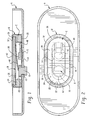
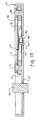
- Figures 1 and 2 show a metal housing member A in the form of an end cap, lid or cover for a battery case. It will be recognized that the switch assemblies of the present application can be used with batteries by attaching the switch assembly thereto in ways other than by attachment to the battery case or end cap. It also will be recognized that the switch assembly may be attached to a housing member other than a battery cover or case where protection is desired against excessive temperature or pressure conditions internally of the housing.
- a suitable hole is provided in housing member A for receiving a metal rivet 10 that is then deformed for attaching same to housing member A.
- Metal rivet A defines a fixed electrical contact, and electrical insulation 12 is interposed between the periphery of fixed contact 10 and housing A.
- a circular pressure port defined by hole 14 in housing member A is normally closed by a snap-acting flexible metal foil diaphragm 16.
- the peripheral undersurface of diaphragm 16 is welded or otherwise sealingly attached to the surface of housing member A surrounding hole 14.
- the central portion of diaphragm 16 is formed to the shape of a smoothly curved dome, dimple or bubble that is shown in a concave configuration extending downwardly into hole 14 in Figure 1, and that snaps to an opposite upwardly domed convex configuration above hole 14 in response to a predetermined elevated pressure acting thereon.
- the curved bubble is convex in a direction toward the source of possible elevated pressure, and snaps to a reverse curvature in which it is convex in a direction away from the source of elevated pressure.
- An insulator attachment ring B has an inwardly extending bottom flange 20 welded or otherwise secured to housing member A in outwardly-spaced surrounding relationship to fixed contact 10 and pressure port 14.
- a support ring C of electrical insulating material is received in attachment ring B and has a central opening 22 therethrough with an opening periphery located in outwardly-spaced surrounding relationship to fixed contact 10 and hole 14.
- An upper peripheral notch or recess 24 in support ring C is stepped outwardly from opening 22 for supporting an annular base portion 26 of a switch blade member D.
- a metal terminal plate 30 is positioned on base portion 26 of switch blade member D within recess 24.
- An electrical insulating washer 32 is positioned against the outer peripheral portion of metal plate 30 and the top surface of insulator C, and attachment ring B is inwardly deformed to provide an inwardly extending top flange 36 that secures switch blade member D and metal plate 30 within insulator recess 24.
- the flange 36 is deformed such that the peripheral underside of terminal plate 30 preferably is in compressive engagement with base portion 26 of switch blade member D for minimizing resistance and providing optimum conductivity.
- a flexible switch blade 40 extending into the opening within annular base portion 26 of switch member D is bent downwardly from base portion 26 and has a free end portion normally engaging fixed contact 10 that is electrically connectable with a battery electrode.
- An electrical lead may be soldered, welded or otherwise attached to the outer surface of metal terminal plate 30 for connection to a device that is to be powered by the battery.
- switch blade 40 is in the battery circuit in this example and completes a circuit between fixed contact 10 and metal terminal plate 30.
- a movable force transfer member such as a bumper 42 of electrical insulating material is interposed between snap-acting flexible foil diaphragm 16 and switch blade 40.
- dielectric support C has top and bottom surfaces 44, 46, and peripheral recess 24 is located adjacent top surface 44.
- Bumper 42 is molded integrally in one-piece with insulator C and extends into insulator opening 22 from one end thereof. Bumper 42 is connected with the main body portion of insulator C by flexible arms 48, 50.
- attachment ring B and insulator C are oval, although it will be recognized that other shapes also are possible.
- flexible arms 48, 50 preferably are attached to the body portion of insulator C at one of the ends of the elongated configuration.
- switch blade member D preferably is of shape memory alloy such as a nickel-titanium shape memory alloy.
- shape memory alloys such as copper-based ternaries including copper-zinc-aluminum and copper-nickel-aluminum.
- the transition temperature range at which the alloy changes from its deformed shape to its recovered shape can be varied by selecting different shape memory alloy compositions and by varying the heat treatment process.
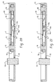
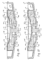
- switch blade member D of shape memory alloy In manufacturing switch blade member D of shape memory alloy, the entire switch blade member is heated to the austenitic transformation temperature of the shape memory metal. After cooling to its martensitic state, switch blade 40 is bent relative to base portion 26 to the desired configuration generally shown in Figure 10. When switch blade 40 again is heated to its austenitic transformation temperature, it reverts back to the general configuration that it had before it was bent.
- the bent configuration of Figures 1 and 10 is commonly known as the deformed shape that the shape memory metal has at normal temperatures.
- the configuration that the switch blade assumes at its austenitic transformation temperature is shown in Figure 11 and is known as its recovered shape.
- switch blade 40 In response to an elevated temperature condition and/or in response to I 2 R heating of switch blade 40, the switch blade moves from its closed position to the open position shown in Figure 11 by assuming its recovered shape at the predetermined austenitic transformation temperature of the alloy. Switch blade 40 can be treated and processed to remain permanently in the open position or to return to the closed position upon cooling. In batteries, the preferred arrangement is to have the device remain open and function as a one-shot fuse so that the battery circuit will not reclose once a problem condition has been sensed.
- diaphragm 16 In response to an elevated pressure acting on diaphragm 16 on the opposite side thereof from bumper 42, diaphragm 16 snaps to its opposite domed or bubble configuration as shown in Figure 12 to move bumper 42 and lift switch blade 40 from engagement with fixed contact 10. In the event of excessive pressure, foil diaphragm 16 may rupture for allowing relief of pressure through hole 14.
- One or more vent openings may be provided through terminal plate 30 or support C and attachment ring B to vent the cavity or chamber within which switch blade 40 is situated.
- the pressure responsive snap-acting diaphragm preferably is bistable and remains in the position of Figure 12 even though the elevated pressure dissipates.
- the biasing force of switch blade 40 is insufficient to collapse the bubble so that the bubble holds the blade in its open position.
- This also is the preferred arrangement for other embodiments in which the diaphragm bubble holds the switch member in either its open or its closed position.
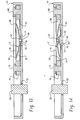
- FIG 13 shows another arrangement wherein a battery terminal 50 extends through a suitable hole in housing member A1 and is electrically isolated therefrom by electrical insulation 52.
- a pressure port defined by circular hole 54 in housing member A1 is normally closed by a snap-acting flexible foil diaphragm 56 that supports a bumper 58 having a central vent hole 60 therethrough and a central stem 62.
- An electrically conductive metal foil 64 that defines a fixed contact is positioned on housing member A and is normally engaged by the undersurface of the central portion of a snap-acting bimetal bowed disc or bowed strip switch member E.
- the central portion of switch member E has a guide hole loosely receiving bumper stem 62.
- the periphery or peripheral end edges 66, 68 of bimetal bowed disc or bowed strip switch member E engage the undersurface of a metal terminal plate 70 supported on an insulator support ring 76 attached to housing member A as by rivets 78, 80.
- An electrical insulating member or dielectric foil 82 is positioned on conductive foil 64 outwardly of bumper 58 and the central portion of switch member E.
- Figure 13 shows the closed position of the switch with a circuit being completed from conductive foil 64 to the central portion of switch member E and then through switch member E to its periphery and to metal terminal plate 70.
- switch member E assumes the configuration shown in Figure 14 with the periphery or peripheral end edges 66, 68 of the bimetal bowed disc or bowed strip engaging insulator foil 82 to provide an open circuit.
- Conductive foil 64 may have a plurality of radial score lines extending in a direction away from bumper 58 so that the foil will rupture along the score lines to facilitate movement of bumper 58 therethrough to the position of Figure 14.
- FIG 15 shows the open position of the switch in response to an elevated temperature.
- Snap-acting bimetal switch member E separates from bumper 58 and assumes the inverted bowed configuration with its central portion engaging or located adjacent to metal terminal plate 70, and with peripheral edges 66, 68 engaging insulator foil 82. Any condition that generates an elevated pressure also will cause an elevated temperature. An elevated temperature softens the bimetal so that it will snap to a reversed configuration with the boost provided by the bumper even though the elevated temperature itself may not be quite adequate to cause reverse snapping.
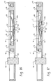
- Figure 16 shows an arrangement similar to Figure 13 except that the switch is normally open rather than normally closed as in Figure 13.
- insulator foil 82a is interposed between the central portion of switch member E and conductive foil 64 so that there is no circuit from conductive foil 64 through switch member E to metal terminal plate 70.
- snap-acting bimetal switch member E assumes the configuration shown in Figure 17 with the disc periphery or strip peripheral end edges 66, 68 of a bowed snap-acting bimetal switch member E engaging conductive foil 64 outwardly of insulator 82a.
- the upper central portion of switch member E engages the underside of metal terminal plate 70 to complete a circuit through switch member E from conductive foil 64 to metal plate 70.
- Conductive foil 64 may have a plurality of radial score lines adjacent bumper 58 so that the foil will rupture when the diaphragm moves to the position of Figure 17.
- Figure 18 shows the arrangement of Figure 16 in a closed position in response to an elevated temperature.
- bimetal E When bimetal E is heated to a predetermined temperature, it snaps to the inverted position shown in Figure 18 with its central portion engaging the underside of metal terminal plate 70 and with its peripheral edge or end edges 66, 68 engaging conductive foil 64.
- bimetal E snaps inverted in response to temperature, it separates from bumper 58 as shown in Figure 18.
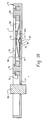
- Figure 19 shows another arrangement similar to Figure 13 but with a different kind of switch member.
- the periphery 89 of an annular base portion on switch member F is supported on insulator support ring 76 beneath metal plate 70.
- a switch blade member 90 of shape memory metal normally projects inwardly from annular or ring base portion 89 and engages electrically conductive foil 64 to complete a circuit between foil 64 and metal plate 70.
- Switch blade 90 is movable to an open position as shown in Figure 20 upon assuming its recovered shape at an elevated temperature.
- switch blade member 90 assumes its open position in response to an elevated pressure as shown in Figure 21.
- Flexible foil diaphragm 56a snaps in a direction toward switch blade 90 carrying bumper 58a therewith to place switch blade 90 in its open position. Hole 60a in bumper 58a allows venting of pressure therethrough upon rupture of diaphragm 56a in response to excessive pressure.
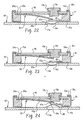
- Figure 22 shows an arrangement similar to Figure 1 except that the switch is normally open instead of normally closed as in Figure 1.
- metal terminal plate 96 has fixed contact 10a attached thereto and isolated therefrom by electrical insulation 12a.
- Switch blade 40a of shape memory metal in Figure 22 moves from an open position to a closed position as shown in Figure 23 by changing to its recovered shape in response to an elevated temperature in the chamber within which it is situated and/or in response to self-induced I 2 R heating.
- switch blade 40a may be moved from its open position to its closed position by an elevated pressure acting through pressure port 14a on the opposite side of snap-acting diaphragm 16a from bumper 42a as shown in Figure 24.
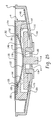
- Figure 25 shows another arrangement wherein a metal housing member G such as a lid or end cap for a battery case or the like has a cylindrical guide sleeve 110 secured thereto.
- a disc 112 of electrical insulating material is attached to the interior of guide sleeve 110 and to a battery terminal 114 that is connected to a battery electrode.
- a movable force transfer member 116 of electrical insulating material has a central hole 118 therethrough freely receiving battery terminal 114.
- a circular recess 120 in the underside of movable force transfer member 116 slidably receives guide sleeve 110.
- Force transfer member 116 may be termed an actuator, and may be a disc or a generally rectangular bar with opposite end portions.
- a bowed strip or bowed disc switch member 122 of bimetal or shape memory material has a central portion normally engaging terminal 114, and outer peripheral edge or edges 126, 128 normally engaging a metal terminal plate 130.
- An attachment ring H has an outwardly extending flange 140 welded or otherwise secured to housing member G.
- An electrical insulating support ring member 142 is received within attachment ring H on housing member G.
- Inwardly extending supports 144, 146 support the peripheral or end portions of switch member 122, and the bottom of a recess 150 supports metal terminal plate 130.
- An electrical insulating washer 152 is positioned on the top surface of insulating ring 142 and metal terminal plate 130, and the upper peripheral portion of attachment ring H is deformed inwardly into a securing flange 154.
- Recesses 160 and 162 are located outwardly of switch member ends 126, 128 between supports 144, 146 and metal terminal plate 130.
- switch member 122 preferably is of shape memory metal but it also may be a bimetal.
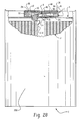
- Figure 28 shows the switch assembly of Figure 1 attached to a battery or electrochemical cell I having a metal case 200 with lid or end cap A welded thereto. It will be recognized that the other embodiments may be attached to the case of a battery or electrochemical cell in a similar manner.
- Case 200 may have many different configurations including, but not necessarily limited to, cylindrical and rectangular.
- Case 200 may contain a wrapped multi-layer assembly J that forms the battery electrodes, and a wire 210 is attached between the electrode and fixed contact 10.
- One electrode of electrode assembly J is attached to fixed contact 10 as by wire 210 while the other electrode is connected to battery case 200.
- fixed contact 10 is the positive battery terminal while the battery case and the lid are the negative terminal.
- either the positive or negative battery electrode may be connected with the battery case while the opposite electrode is connected with the fixed contact.
- a positive or negative battery electrode may be connected with the battery case, of which housing member A1 is a part, and the opposite electrode is connected with fixed contact 50.
- the positive or negative battery electrode is connected with the battery case, of which housing member G is a part, and the opposite electrode is connected with fixed contact 114.
- Electrode assembly J may be of many types including stacked, plate and spirally wound, and is generally shown as a spirally wound or jelly roll type. In such a construction, strips of anode and cathode material with a separator strip between them are wound into a shape for reception in the open top portion of the battery case that has integral peripheral and bottom walls.
- the anode material is a consumable metal and the cathode material is reducible by electrochemical action.
- the separator may be a porous electrical insulator material that is ionically conductive.
- the electrode assembly is inserted into the container forming the battery case, and an electrolyte of solvent containing a conductive solute is added to the container. The cover or end cap then is attached sealingly to the open top of the container to seal the electrode assembly and electrolyte within the battery case.
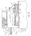
- electrical leads 250, 252 for a signal circuit are soldered, welded or otherwise attached to metal plate 96 and fixed contact 10a of the normally open switch assembly described with reference to Figures 22-24, and are connected with a controller K.
- Leads 254, 256 connect controller K with a charging circuit M that in turn is connected by leads 258, 260 with terminals 262, 264 of an electrochemical cell N.
- the arrangement of Figure 29 may be used in a system that has a plurality of individual cells that are constantly charging, such as in an electrochemical cell package that includes a plurality of individual cells for an electric vehicle.
- Each individual cell would have a sensing switch in accordance with the present application associated with the cell housing to sense an excessive pressure or temperature condition. When such a condition is sensed, the switch closes to send a signal to controller K for cutting off charging current to that particular cell while leaving the remaining cells in service.
- Other normally open embodiments may be used in the same manner.
- Lid A and attachment ring B are nickel plated cold rolled steel.
- Fixed contact 10 is aluminum.
- Shape memory actuator D is nickel-titanium provided with a gold strike covered by silver plating on all surfaces, including peripheral surfaces. This provides current flow from precious metal on one surface to the other surface through the peripheral precious metal.
- Terminal or contact plate 30 is silver plated brass, including opposite surfaces and the peripheral surface.
- Diaphragm 16 is of aluminum. Similar parts in other embodiments are of similar materials and platings.
- foil contact 64 is of a precious metal such as silver or gold or a metal foil plated with a precious metal.
- the improvements of the present application are not necessarily limited to these particular materials and platings.
- the resistance of the switch assembly is less than 20 milliohms, more preferably less than 12 milliohms, and most preferably not greater than 6 milliohms. In the embodiment of Figure 1, this resistance is measured across the outer surfaces of metal terminal plate 30 and fixed contact 10. When closed, the movable switch member or blade has sufficient stiffness and bending strength to engage the fixed contact with a force of at least 150 grams.
- the extremely low resistance is achieved by plating the parts as indicated, by placing the terminal plate in compression against the periphery of the switch member and by providing high force of engagement between the switch member and the fixed contact.
- the other embodiments have a corresponding low resistance.
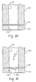
- Figures 30 and 31 show an aluminum foil diaphragm 270 peripherally clamped in sealed relationship between cylindrical dies 272, 274 having central cylindrical passages 276, 278 therethrough.
- Passage 276 in die 272 is connected through a suitable control with a source of high fluid pressure that preferably is air but could be a liquid.
- a source of high fluid pressure that preferably is air but could be a liquid.
- the pressure acts uniformly on foil 270 to deform same into cylindrical passage 278 in die 274 and provide a smoothly curved bubble or dome 280 therein.
- the bubble is formed by a substantially uniform pressure acting on the entire area of the bubble.
- the fluid pressure used to produce bubble 280 in an 1100 or 3003 series aluminum foil having a thickness between 2/1000 - 6/1000 inch may be around 300 p.s.i.g.
- the pressure required to reverse the direction of the bubble usually is slightly greater, such as around 320 p.s.i.g.
- the bubble collapses and reverses with snap action when the pressure acting on it is at least equal to, and usually slightly greater than, the pressure that formed it.
- Many different materials may be used for the foil diaphragm, including nickel plated steel, as long as the material is compatible with the electrolyte used in the cell.
- the fluid pressure used to form the bubble may vary depending on the thickness and properties of the foil, and the application in which the diaphragm will be used.
- the diaphragm preferably snaps in a reverse direction at a pressure of at least 250 p.s.i.g., and more preferably within 10% of at least 300 p.s.i.g.
- snap action at other pressures can be used.
- one or more vent openings may be provided for the chamber in which the switch member is positioned in the event the diaphragm ruptures due to excessive pressure.
- Shape memory alloys or bimetal materials may be selected to have a wide range of transformation or transition temperatures.
- the shape memory alloy or bimetal material selected is one that has a transformation or transition temperature approximating that of the over temperature condition to be protected against.
- transformation temperatures for shape memory materials plus or minus 5°, include 62°C, 73°C and 82°C. These examples would have transformation temperature ranges of approximately 57-67°C, 58-78°C and 77-87°C. It will be recognized that a wide range of shape memory alloys or bimetal materials may be chosen depending upon the application for the thermal switch assembly.
- the switch can be fabricated to change from a normally closed or normally open position to the opposite position at an elevated temperature in the range of about 60-125°C. A preferred range is about 65-75°C.
- the switch of the present application preferably functions as a one-shot fuse by remaining in the position it assumes in response to an elevated temperature or pressure even after the elevated temperature or pressure dissipates.
- a normally closed switch that moves to an open position in response to an elevated temperature or pressure will remain open rather than reclosing upon dissipation of the elevated temperature or pressure that initially caused the movement.
- this may be done by using a fuse disc or fuse strip bimetal material that snaps to a different position upon being heated to a predetermined temperature and does not revert to its original position when cooled.
- this may be done by using a shape memory material that moves to a different position upon being heated to a predetermined temperature and changing from its deformed state to its recovered state, and does not revert to its deformed state or its original position upon cooling.
- the snap-acting pressure responsive diaphragm preferably is bistable. Upon snapping to its opposite position under the influence of a predetermined pressure, the diaphragm remains in that opposite position even though the pressure dissipates. The force of the switch member acting on the diaphragm is insufficient to collapse the diaphragm so that it holds the switch member in the position that it is moved to in response to an elevated pressure even after the pressure dissipates.
- the bimetal material may be one that snaps to a new position upon being heated to a predetermined elevated temperature and snaps back to its original position upon cooling.
- the shape memory material may be one that moves to a new position upon being heated to a predetermined temperature by changing from its deformed shape to its recovered shape, and reverts to both its original position and its deformed state upon cooling.
- the diaphragm may be one that is not bistable, or a supplemental biasing force may be provided to collapse the diaphragm bubble and allow movement of the switch member back to its original position upon dissipation of the elevated pressure. It also is possible to provide a manual reset button to reset the switch member back to its original position.
- the position of the diaphragm bubble when it extends toward the source of high pressure such as in Figure 1 may be considered a passive position, and its opposite position holding the switch member in its alternative position such as in Figure 12 may be considered an operational position.
- the terminal plate and the fixed contact formed by the aluminum rivet or foil may be called conductors or metal members that are connected in a closed position of the switch member and are disconnected in the open position of the switch member.
- the foil fixed contact may be welded or otherwise attached to the housing member to provide low resistance.
Landscapes
- Physics & Mathematics (AREA)
- Thermal Sciences (AREA)
- Fluid Mechanics (AREA)
- Thermally Actuated Switches (AREA)
- Switches Operated By Changes In Physical Conditions (AREA)
- Connection Of Batteries Or Terminals (AREA)
Applications Claiming Priority (2)
| Application Number | Priority Date | Filing Date | Title |
|---|---|---|---|
| US09/372,739 US6342826B1 (en) | 1999-08-11 | 1999-08-11 | Pressure and temperature responsive switch assembly |
| US372739 | 1999-08-11 |
Publications (2)
| Publication Number | Publication Date |
|---|---|
| EP1076350A2 true EP1076350A2 (de) | 2001-02-14 |
| EP1076350A3 EP1076350A3 (de) | 2002-11-06 |
Family
ID=23469431
Family Applications (1)
| Application Number | Title | Priority Date | Filing Date |
|---|---|---|---|
| EP00306742A Withdrawn EP1076350A3 (de) | 1999-08-11 | 2000-08-08 | Druck- und temperaturempfindlicher Schalter |
Country Status (7)
| Country | Link |
|---|---|
| US (1) | US6342826B1 (de) |
| EP (1) | EP1076350A3 (de) |
| JP (1) | JP2001084880A (de) |
| KR (1) | KR20010021236A (de) |
| CA (1) | CA2315429A1 (de) |
| MX (1) | MXPA00007756A (de) |
| TW (1) | TW459258B (de) |
Cited By (31)
| Publication number | Priority date | Publication date | Assignee | Title |
|---|---|---|---|---|
| WO2007093626A1 (en) * | 2006-02-17 | 2007-08-23 | Nilar International Ab | A bipolar battery including a pressure sensor |
| EP1422771A4 (de) * | 2001-08-07 | 2009-01-21 | Panasonic Corp | Sekundärbatterie mit wasserfreiem elektrolyt |
| EP1990020A3 (de) * | 2007-05-11 | 2009-03-04 | Covidien AG | Temperaturüberwachende Neutralelektrode |
| EP1795734A3 (de) * | 2005-12-09 | 2009-09-09 | Mahle International GmbH | Steuerungsvorrichtung einer Heizeinrichtung |
| CN101950812A (zh) * | 2009-07-09 | 2011-01-19 | Sb锂摩托有限公司 | 可再充电电池 |
| CN101997133A (zh) * | 2009-08-14 | 2011-03-30 | Sb锂摩托有限公司 | 可再充电电池 |
| CN102005597A (zh) * | 2009-09-01 | 2011-04-06 | Sb锂摩托有限公司 | 可再充电电池 |
| US20120070705A1 (en) * | 2010-09-17 | 2012-03-22 | Sung-Bae Kim | Rechargeable battery |
| US8187263B2 (en) | 2008-02-04 | 2012-05-29 | Tyco Healthcare Group Lp | System and method for return electrode monitoring |
| US20120141845A1 (en) * | 2010-12-02 | 2012-06-07 | Sang-Won Byun | Rechargeable battery |
| US20120214030A1 (en) * | 2011-02-18 | 2012-08-23 | Minhyung Guen | Secondary battery |
| EP2509149A1 (de) * | 2011-04-04 | 2012-10-10 | SB LiMotive Co., Ltd. | Sekundärbatterie |
| US8323813B2 (en) | 2009-05-14 | 2012-12-04 | Sb Limotive Co., Ltd. | Rechargeable battery including an extensible member |
| US8388614B2 (en) | 2009-09-29 | 2013-03-05 | Covidien Lp | Return electrode temperature prediction |
| EP2568518A1 (de) * | 2011-09-06 | 2013-03-13 | Samsung SDI Co., Ltd. | Wiederaufladbare Batterie |
| US8486059B2 (en) | 2008-02-15 | 2013-07-16 | Covidien Lp | Multi-layer return electrode |
| US8523853B2 (en) | 2008-02-05 | 2013-09-03 | Covidien Lp | Hybrid contact quality monitoring return electrode |
| EP2485292A3 (de) * | 2011-02-08 | 2013-11-27 | Samsung SDI Co., Ltd. | Sekundärbatterie |
| US9012050B2 (en) | 2011-07-26 | 2015-04-21 | Samsung Sdi Co., Ltd. | Rechargeable battery |
| US9054371B2 (en) | 2011-11-17 | 2015-06-09 | Samsung Sdi Co., Ltd. | Rechargeable battery |
| CN105552258A (zh) * | 2016-02-04 | 2016-05-04 | 宁德时代新能源科技股份有限公司 | 二次电池及其顶盖 |
| US9539051B2 (en) | 2007-08-01 | 2017-01-10 | Covidien Lp | System and method for return electrode monitoring |
| US9636128B2 (en) | 2006-10-05 | 2017-05-02 | Covidien Lp | Method and force-limiting handle mechanism for a surgical instrument |
| EP3255704A1 (de) * | 2016-06-07 | 2017-12-13 | Contemporary Amperex Technology Co., Limited | Hochleistungsbatteriedeckel und hochleistungsbatterie |
| US9987072B2 (en) | 2008-03-17 | 2018-06-05 | Covidien Lp | System and method for detecting a fault in a capacitive return electrode for use in electrosurgery |
| US10008710B2 (en) | 2014-08-04 | 2018-06-26 | Johnson Controls Technology Company | Overcharge protection assembly for a battery module |
| US10938017B2 (en) | 2016-08-01 | 2021-03-02 | Cps Technology Holdings Llc | Overcharge protection assembly for a battery cell |
| WO2021259730A1 (en) * | 2020-06-23 | 2021-12-30 | Jt International Sa | Electrical fuse system |
| US11233289B2 (en) | 2016-08-01 | 2022-01-25 | Cps Technology Holdings Llc | Weldable aluminum terminal pads of an electrochemical cell |
| US11245163B2 (en) | 2016-08-01 | 2022-02-08 | Cps Technology Holdings Llc | Overcharge protection systems for prismatic lithium ion battery cells with biased packaging |
| US11364076B2 (en) | 2019-12-12 | 2022-06-21 | Covidien Lp | Monopolar return pad |
Families Citing this family (76)
| Publication number | Priority date | Publication date | Assignee | Title |
|---|---|---|---|---|
| EP1146579B1 (de) * | 2000-04-12 | 2011-06-08 | Panasonic Corporation | Ladbare Batterie mit nichtwässrigem Elektrolyten |
| WO2002099442A2 (en) | 2001-06-01 | 2002-12-12 | Sherwood Services Ag | Return pad cable connector |
| JP4984359B2 (ja) * | 2001-08-08 | 2012-07-25 | パナソニック株式会社 | 密閉型電池およびその封口板 |
| JP4672219B2 (ja) * | 2001-09-11 | 2011-04-20 | ウチヤ・サーモスタット株式会社 | 安全装置 |
| US6673489B2 (en) * | 2001-12-28 | 2004-01-06 | Quallion Llc | Electric battery assembly and method of manufacture |
| US6832015B2 (en) * | 2002-06-28 | 2004-12-14 | Hewlett-Packard Development Company, L.P. | Switching apparatus |
| WO2004027955A2 (en) * | 2002-09-19 | 2004-04-01 | Quallion Llc | Battery charging system |
| US6860881B2 (en) | 2002-09-25 | 2005-03-01 | Sherwood Services Ag | Multiple RF return pad contact detection system |
| JP2004332593A (ja) * | 2003-05-06 | 2004-11-25 | Ubukata Industries Co Ltd | 電動圧力機器用保護装置 |
| EP1607628B1 (de) * | 2004-06-10 | 2007-03-28 | C.R.F. Società Consortile per Azioni | Verfahren und System zur Regelung von Aktuatoren aus Formgedächtnislegierungen |
| KR100584404B1 (ko) * | 2004-11-11 | 2006-05-26 | 삼성전자주식회사 | 이동 통신 단말기의 배터리 장치 및 그 운용 방법 |
| CA2541037A1 (en) | 2005-03-31 | 2006-09-30 | Sherwood Services Ag | Temperature regulating patient return electrode and return electrode monitoring system |
| KR100948971B1 (ko) * | 2005-09-28 | 2010-03-23 | 주식회사 엘지화학 | 안전장치를 구비하고 있는 각형 이차전지 |
| US7736359B2 (en) | 2006-01-12 | 2010-06-15 | Covidien Ag | RF return pad current detection system |
| US7763375B2 (en) * | 2006-05-24 | 2010-07-27 | Eveready Battery Company, Inc. | Current interrupt device for batteries |
| JP2008039502A (ja) * | 2006-08-03 | 2008-02-21 | Alps Electric Co Ltd | 接触子およびその製造方法 |
| US7637907B2 (en) | 2006-09-19 | 2009-12-29 | Covidien Ag | System and method for return electrode monitoring |
| US7927329B2 (en) | 2006-09-28 | 2011-04-19 | Covidien Ag | Temperature sensing return electrode pad |
| US7722603B2 (en) | 2006-09-28 | 2010-05-25 | Covidien Ag | Smart return electrode pad |
| US7639114B2 (en) * | 2006-11-22 | 2009-12-29 | Tsung-Mou Yu | Temperature fuse protection device |
| US8021360B2 (en) | 2007-04-03 | 2011-09-20 | Tyco Healthcare Group Lp | System and method for providing even heat distribution and cooling return pads |
| US20080254343A1 (en) * | 2007-04-16 | 2008-10-16 | Eveready Battery Company, Inc. | Electrochemical cell with thermal current interrupting switch |
| US8080007B2 (en) | 2007-05-07 | 2011-12-20 | Tyco Healthcare Group Lp | Capacitive electrosurgical return pad with contact quality monitoring |
| US8388612B2 (en) | 2007-05-11 | 2013-03-05 | Covidien Lp | Temperature monitoring return electrode |
| US8100898B2 (en) | 2007-08-01 | 2012-01-24 | Tyco Healthcare Group Lp | System and method for return electrode monitoring |
| US8026784B2 (en) * | 2007-08-07 | 2011-09-27 | Hella Kgaa | Ganged power circuit switches for on-board electrical system in motor vehicles |
| JP5000540B2 (ja) * | 2008-01-31 | 2012-08-15 | 新光電気工業株式会社 | スイッチング機能付配線基板 |
| US7808361B1 (en) * | 2008-11-25 | 2010-10-05 | Tsung Mou Yu | Dual protection device for circuit |
| US8298225B2 (en) | 2009-03-19 | 2012-10-30 | Tyco Healthcare Group Lp | System and method for return electrode monitoring |
| US9023513B2 (en) * | 2009-08-27 | 2015-05-05 | Samsung Sdi Co., Ltd. | Rechargeable secondary battery having improved safety against puncture and collapse |
| US8440336B2 (en) * | 2009-12-08 | 2013-05-14 | Samsung Sdi Co., Ltd. | Rechargeable battery with short circuit member |
| US8632911B2 (en) * | 2010-01-15 | 2014-01-21 | Samsung Sdi Co., Ltd. | Rechargeable battery |
| KR101042808B1 (ko) * | 2010-01-26 | 2011-06-20 | 에스비리모티브 주식회사 | 이차 전지 |
| KR101094046B1 (ko) * | 2010-01-26 | 2011-12-19 | 에스비리모티브 주식회사 | 이차 전지 |
| KR101116449B1 (ko) * | 2010-01-26 | 2012-02-27 | 에스비리모티브 주식회사 | 이차 전지 |
| KR101217071B1 (ko) * | 2010-02-18 | 2012-12-31 | 로베르트 보쉬 게엠베하 | 이차 전지 |
| US8748030B2 (en) * | 2010-06-09 | 2014-06-10 | Samsung Sdi Co., Ltd. | Secondary battery |
| US8501341B2 (en) | 2010-06-30 | 2013-08-06 | Samsung Sdi Co., Ltd. | Rechargeable battery |
| US8652134B2 (en) * | 2011-02-08 | 2014-02-18 | Gyrus Medical, Inc. | Single-use electronic apparatus having a thermal switch |
| KR101243475B1 (ko) * | 2011-03-30 | 2013-03-13 | 로베르트 보쉬 게엠베하 | 단락 부재를 구비한 이차 전지 |
| CN103140912B (zh) * | 2011-05-31 | 2015-07-22 | 松下电器产业株式会社 | 熔断器板 |
| CN103733378B (zh) | 2011-06-13 | 2016-08-31 | 江森自控帅福得先进能源动力系统有限责任公司 | 用于帮助电化学电池的通风口的断裂的装置 |
| KR101352840B1 (ko) * | 2012-02-08 | 2014-01-21 | 주식회사 아이티엠반도체 | 배터리 과열 방지 어셈블리 및 이를 갖는 배터리 팩 |
| EP2838138B1 (de) * | 2012-04-12 | 2019-02-27 | Kabushiki Kaisha Toyota Jidoshokki | Stromunterbrecher und stromspeichervorrichtung damit |
| KR101349013B1 (ko) * | 2012-04-23 | 2014-01-10 | 현대자동차주식회사 | 형상기억소재를 이용한 전자전기 부품의 하우징 |
| US9543563B2 (en) * | 2012-07-19 | 2017-01-10 | Kabushiki Kaisha Toyota Jidoshokki | Electric storage device including current interruption device |
| DE102012014595A1 (de) * | 2012-07-24 | 2014-01-30 | Phoenix Contact Gmbh & Co. Kg | Vorrichtung zum Schutz vor thermischer Überlastung eines zu schützenden Bauteils |
| US9209497B2 (en) * | 2012-12-17 | 2015-12-08 | Infineon Technologies Ag | Sensor module and battery elements |
| KR101666258B1 (ko) * | 2013-01-23 | 2016-10-13 | 삼성에스디아이 주식회사 | 이차 전지 |
| JP6077937B2 (ja) * | 2013-05-30 | 2017-02-08 | 株式会社豊田自動織機 | 電流遮断装置及び蓄電装置 |
| JP2015056380A (ja) * | 2013-09-13 | 2015-03-23 | 株式会社豊田自動織機 | 電流遮断装置及びそれを用いた蓄電装置 |
| US9627722B1 (en) | 2013-09-16 | 2017-04-18 | American Lithium Energy Corporation | Positive temperature coefficient film, positive temperature coefficient electrode, positive temperature coefficient separator, and battery comprising the same |
| US9478377B2 (en) * | 2013-10-16 | 2016-10-25 | Kabushiki Kaisha Toyota Jidoshokki | Current interruption device and electricity storage device using the same |
| US9692038B2 (en) * | 2013-11-25 | 2017-06-27 | Tesla, Inc. | Cap for electrochemical cell |
| JP5910624B2 (ja) * | 2013-12-26 | 2016-04-27 | 株式会社豊田自動織機 | 電池パック |
| KR102154330B1 (ko) * | 2014-02-05 | 2020-09-09 | 삼성에스디아이 주식회사 | 이차 전지 |
| KR102198005B1 (ko) * | 2014-03-20 | 2021-01-04 | 삼성에스디아이 주식회사 | 이차 전지 |
| US9985271B2 (en) * | 2014-07-31 | 2018-05-29 | Johnson Controls Technology Company | Overcharge protection device for a battery module |
| US10020487B2 (en) | 2014-11-25 | 2018-07-10 | American Lithium Energy Corporation | Rechargeable battery with voltage activated current interrupter |
| CN115603009A (zh) | 2014-11-25 | 2023-01-13 | 美国锂能源公司(Us) | 配置在可充电电池中的保护层、可充电电池及方法 |
| US10020545B2 (en) | 2014-11-25 | 2018-07-10 | American Lithium Energy Corporation | Rechargeable battery with resistive layer for enhanced safety |
| JP6332238B2 (ja) * | 2015-05-14 | 2018-05-30 | トヨタ自動車株式会社 | 二次電池 |
| DE102016107971A1 (de) | 2015-05-14 | 2016-11-17 | Toyota Jidosha Kabushiki Kaisha | Sekundärbatterie |
| KR102093386B1 (ko) * | 2016-06-22 | 2020-03-25 | 주식회사 엘지화학 | 이차 전지 및 이차 전지의 전류 차단 방법 |
| JP6493352B2 (ja) * | 2016-10-13 | 2019-04-03 | トヨタ自動車株式会社 | 二次電池 |
| CN106784562B (zh) * | 2016-12-13 | 2023-01-06 | 芜湖天量电池系统有限公司 | 一种锂电池的电连接组件 |
| EP3869600B1 (de) * | 2017-05-01 | 2022-10-19 | American Lithium Energy Corporation | Stromversorgungssystem und sicherung aufweisend eine platte mit negativer wärmeausdehnung |
| KR101901212B1 (ko) * | 2017-05-31 | 2018-09-27 | 한국과학기술연구원 | 열구동 스위치 구조체 및 그 제조 방법 |
| US10461291B2 (en) * | 2017-12-12 | 2019-10-29 | Ford Global Technologies, Llc | Current-interrupt device for battery cell |
| JP7154782B2 (ja) * | 2018-03-15 | 2022-10-18 | イリソ電子工業株式会社 | 可動コネクタ |
| CN110391366B (zh) * | 2018-04-23 | 2020-11-20 | 比亚迪股份有限公司 | 电池盖板组件、单体电池、电池模组、动力电池和电动汽车 |
| CN112968258B (zh) * | 2018-04-23 | 2022-10-18 | 比亚迪股份有限公司 | 电池盖板组件、电池、电池模组、动力电池和电动汽车 |
| US12230844B2 (en) | 2018-06-25 | 2025-02-18 | American Lithium Energy Corporation | Safety layer for battery cells |
| CN109192605A (zh) * | 2018-07-27 | 2019-01-11 | 苏州华旃航天电器有限公司 | 一种具有双重控制功能的温度继电器 |
| DE202019106891U1 (de) * | 2019-12-11 | 2020-12-16 | Hugo Benzing Gmbh & Co. Kg | Druckentlastungsvorrichtung |
| CN113437424B (zh) * | 2021-07-01 | 2023-09-15 | 湖南兆科动力新能源有限公司 | 一种新能源汽车的单体式锂电池组 |
Family Cites Families (52)
| Publication number | Priority date | Publication date | Assignee | Title |
|---|---|---|---|---|
| US2497397A (en) | 1946-01-19 | 1950-02-14 | Dales George Franklin | Thermostat switch |
| US2743335A (en) | 1953-09-04 | 1956-04-24 | Gen Motors Corp | Circuit breaker |
| US3213250A (en) | 1962-11-30 | 1965-10-19 | Texas Instruments Inc | Miniature snap acting thermostatic switch |
| US3474372A (en) | 1967-02-16 | 1969-10-21 | Crowell Designs Inc | Temperature-responsive switch having self-contained heater |
| US3707694A (en) | 1970-03-09 | 1972-12-26 | Essex International Inc | Thermally sensitive circuit control apparatus |
| US3801944A (en) | 1972-09-28 | 1974-04-02 | Tri Men Mfg Inc | Temperature-compensated, thermal-activated time delay switch |
| US4028478A (en) * | 1976-05-24 | 1977-06-07 | Union Carbide Corporation | Safety switch for sealed galvanic cells |
| US4035552A (en) | 1976-07-23 | 1977-07-12 | Gte Laboratories Incorporated | Electrochemical cell |
| US4188460A (en) | 1978-05-01 | 1980-02-12 | P. R. Mallory & Co., Inc. | Internal battery fuse |
| CH638101A5 (de) | 1979-05-21 | 1983-09-15 | Cerberus Ag | Brandmelder. |
| US4328406A (en) * | 1979-08-02 | 1982-05-04 | Texas Instruments Incorporated | Condition responsive electrical switch and method of making |
| DE3027304C2 (de) | 1980-07-18 | 1982-09-30 | Sds-Elektro Gmbh, 8024 Deisenhofen | Elektrischer Mehrlagenkontakt |
| US4503131A (en) | 1982-01-18 | 1985-03-05 | Richardson Chemical Company | Electrical contact materials |
| US4395694A (en) | 1982-06-23 | 1983-07-26 | Portage Electric Products, Inc. | Thermostat construction employing aramide insulation |
| JPS59191273A (ja) | 1983-04-14 | 1984-10-30 | Toshiba Battery Co Ltd | 非水溶媒電池 |
| JPS59203376A (ja) | 1983-05-04 | 1984-11-17 | Toshiba Corp | 非水溶媒電池 |
| US4774151A (en) | 1986-05-23 | 1988-09-27 | International Business Machines Corporation | Low contact electrical resistant composition, substrates coated therewith, and process for preparing such |
| JPS63175345A (ja) | 1987-01-16 | 1988-07-19 | Matsushita Electric Ind Co Ltd | 有機電解液電池 |
| US4782318A (en) | 1987-08-12 | 1988-11-01 | Texas Instruments Incorporated | Thermally responsive electric switch apparatus |
| US4821010A (en) | 1987-12-30 | 1989-04-11 | Therm-O-Disc, Incorporated | Thermal cutoff heater |
| US4818641A (en) | 1988-04-04 | 1989-04-04 | Eveready Battery Company | Cell circuit interrupter |
| US4855195A (en) | 1988-07-11 | 1989-08-08 | Eveready Battery Company, Inc. | Electrochemical cell with internal circuit interrupter |
| US4973936A (en) | 1989-04-27 | 1990-11-27 | The United States Of America As Represented By The Administrator Of The National Aeronautics And Space Adminstration | Thermal switch disc for short circuit protection of batteries |
| US5061914A (en) | 1989-06-27 | 1991-10-29 | Tini Alloy Company | Shape-memory alloy micro-actuator |
| US4992339A (en) | 1990-03-14 | 1991-02-12 | Eveready Battery Company, Inc. | Electrochemical cell with circuit disconnect device |
| US4975341A (en) | 1990-04-03 | 1990-12-04 | Eveready Battery Company, Inc. | Electrochemical cell with circuit disconnect device |
| US5026615A (en) | 1990-08-06 | 1991-06-25 | Eveready Battery Company, Inc. | Electrochemical cell with disconnect switch device |
| JPH04292868A (ja) * | 1991-03-20 | 1992-10-16 | Ngk Insulators Ltd | ナトリウム−硫黄電池 |
| JPH04345724A (ja) | 1991-05-22 | 1992-12-01 | Fujitsu Ltd | 非破壊ヒューズ |
| US5188909A (en) | 1991-09-12 | 1993-02-23 | Eveready Battery Co., Inc. | Electrochemical cell with circuit disconnect device |
| JP3203623B2 (ja) | 1992-03-06 | 2001-08-27 | ソニー株式会社 | 有機電解液電池 |
| US5206622A (en) | 1992-04-10 | 1993-04-27 | Texas Instruments Incorporated | Protector device with improved bimetal contact assembly and method of making |
| US5268664A (en) | 1993-01-25 | 1993-12-07 | Portage Electric Products, Inc. | Low profile thermostat |
| US5337036A (en) | 1993-07-28 | 1994-08-09 | Kuczynski Robert A | Miniaturized thermal protector with precalibrated automatic resetting bimetallic assembly |
| US5567539A (en) | 1994-05-23 | 1996-10-22 | Fuji Photo Film Co., Ltd. | Non-aqueous secondary cell |
| JP3261688B2 (ja) | 1994-08-23 | 2002-03-04 | キヤノン株式会社 | 二次電池及びその製造方法 |
| JPH08185849A (ja) | 1994-12-27 | 1996-07-16 | Fuji Elelctrochem Co Ltd | 防爆安全装置を備えた電気化学素子 |
| US5619177A (en) | 1995-01-27 | 1997-04-08 | Mjb Company | Shape memory alloy microactuator having an electrostatic force and heating means |
| JPH08236102A (ja) | 1995-02-27 | 1996-09-13 | Fuji Elelctrochem Co Ltd | 電気化学素子 |
| EP0739047A3 (de) * | 1995-04-21 | 1999-04-07 | Wako Electronics Co., Ltd. | Sicherheitsvorrichtung für einen Akkumulator |
| KR0158845B1 (ko) | 1995-07-28 | 1999-02-18 | 배순훈 | 리튬건전지의 과부하 방지구조 |
| JPH09106804A (ja) | 1995-10-09 | 1997-04-22 | Wako Denshi Kk | 電池の安全装置 |
| US5825275A (en) | 1995-10-27 | 1998-10-20 | University Of Maryland | Composite shape memory micro actuator |
| US5691073A (en) | 1996-04-10 | 1997-11-25 | Duracell Inc. | Current interrupter for electrochemical cells |
| US5879832A (en) | 1996-10-02 | 1999-03-09 | Duracell Inc. | Current interrupter for electrochemical cells |
| US5750277A (en) | 1996-04-10 | 1998-05-12 | Texas Instruments Incorporated | Current interrupter for electrochemical cells |
| JPH10134684A (ja) * | 1996-10-29 | 1998-05-22 | Asahi Keiki Kk | サーモスタット |
| JPH10154530A (ja) * | 1996-11-21 | 1998-06-09 | Ngk Insulators Ltd | リチウム二次電池 |
| CA2233390A1 (en) * | 1997-05-02 | 1998-11-02 | William F. Quinn | Thermal switch assembly |
| US6083639A (en) * | 1997-08-22 | 2000-07-04 | Duracell Inc. | Current interrupter for electrochemical cells |
| US5844464A (en) | 1997-11-24 | 1998-12-01 | Therm-O-Disc, Incorporated | Thermal switch |
| US6210824B1 (en) * | 1998-01-15 | 2001-04-03 | Texas Instruments Incorporated | Current interrupt apparatus for electrochemical cells |
-
1999
- 1999-08-11 US US09/372,739 patent/US6342826B1/en not_active Expired - Fee Related
-
2000
- 2000-08-07 KR KR1020000045585A patent/KR20010021236A/ko not_active Withdrawn
- 2000-08-08 EP EP00306742A patent/EP1076350A3/de not_active Withdrawn
- 2000-08-09 MX MXPA00007756A patent/MXPA00007756A/es unknown
- 2000-08-10 CA CA002315429A patent/CA2315429A1/en not_active Abandoned
- 2000-08-11 JP JP2000243945A patent/JP2001084880A/ja active Pending
- 2000-09-25 TW TW089116104A patent/TW459258B/zh active
Cited By (58)
| Publication number | Priority date | Publication date | Assignee | Title |
|---|---|---|---|---|
| EP1422771A4 (de) * | 2001-08-07 | 2009-01-21 | Panasonic Corp | Sekundärbatterie mit wasserfreiem elektrolyt |
| EP1795734A3 (de) * | 2005-12-09 | 2009-09-09 | Mahle International GmbH | Steuerungsvorrichtung einer Heizeinrichtung |
| CN101411004B (zh) * | 2006-02-17 | 2012-03-21 | 尼拉国际股份公司 | 包括压力传感器的双极电池 |
| WO2007093626A1 (en) * | 2006-02-17 | 2007-08-23 | Nilar International Ab | A bipolar battery including a pressure sensor |
| US9636128B2 (en) | 2006-10-05 | 2017-05-02 | Covidien Lp | Method and force-limiting handle mechanism for a surgical instrument |
| EP1990020A3 (de) * | 2007-05-11 | 2009-03-04 | Covidien AG | Temperaturüberwachende Neutralelektrode |
| US9539051B2 (en) | 2007-08-01 | 2017-01-10 | Covidien Lp | System and method for return electrode monitoring |
| US8790337B2 (en) | 2008-02-04 | 2014-07-29 | Covidien Lp | System and method for return electrode monitoring |
| US8187263B2 (en) | 2008-02-04 | 2012-05-29 | Tyco Healthcare Group Lp | System and method for return electrode monitoring |
| US8523853B2 (en) | 2008-02-05 | 2013-09-03 | Covidien Lp | Hybrid contact quality monitoring return electrode |
| US8486059B2 (en) | 2008-02-15 | 2013-07-16 | Covidien Lp | Multi-layer return electrode |
| US9987072B2 (en) | 2008-03-17 | 2018-06-05 | Covidien Lp | System and method for detecting a fault in a capacitive return electrode for use in electrosurgery |
| US9306197B2 (en) | 2009-05-14 | 2016-04-05 | Samsung Sdi Co., Ltd. | Rechargeable battery including an extensible member |
| US8323813B2 (en) | 2009-05-14 | 2012-12-04 | Sb Limotive Co., Ltd. | Rechargeable battery including an extensible member |
| EP2259364B1 (de) * | 2009-05-14 | 2013-04-03 | Samsung SDI Co., Ltd. | Wiederaufladbare Batterie |
| EP2273587B1 (de) * | 2009-07-09 | 2013-05-29 | Samsung SDI Co., Ltd. | Wiederaufladbare Batterie |
| US9246140B2 (en) | 2009-07-09 | 2016-01-26 | Samsung Sdi Co., Ltd. | Rechargeable battery with a cap assembly having a first tab located outside of the case |
| CN101950812A (zh) * | 2009-07-09 | 2011-01-19 | Sb锂摩托有限公司 | 可再充电电池 |
| CN101997133B (zh) * | 2009-08-14 | 2016-05-25 | 三星Sdi株式会社 | 可再充电电池 |
| US8236439B2 (en) | 2009-08-14 | 2012-08-07 | Sb Limotive Co., Ltd. | Rechargeable battery |
| EP2284932B1 (de) * | 2009-08-14 | 2013-06-05 | Samsung SDI Co., Ltd. | Wiederaufladbare Batterie |
| CN101997133A (zh) * | 2009-08-14 | 2011-03-30 | Sb锂摩托有限公司 | 可再充电电池 |
| CN102005597A (zh) * | 2009-09-01 | 2011-04-06 | Sb锂摩托有限公司 | 可再充电电池 |
| US8877361B2 (en) | 2009-09-01 | 2014-11-04 | Samsung Sdi Co., Ltd. | Rechargeable battery |
| US8388614B2 (en) | 2009-09-29 | 2013-03-05 | Covidien Lp | Return electrode temperature prediction |
| US8784410B2 (en) | 2009-09-29 | 2014-07-22 | Covidien Lp | Return electrode temperature prediction |
| US20120070705A1 (en) * | 2010-09-17 | 2012-03-22 | Sung-Bae Kim | Rechargeable battery |
| US9293756B2 (en) * | 2010-09-17 | 2016-03-22 | Samsung Sdi Co., Ltd. | Rechargeable battery |
| US9478774B2 (en) | 2010-12-02 | 2016-10-25 | Samsung Sdi Co., Ltd. | Rechargeable battery |
| US20120141845A1 (en) * | 2010-12-02 | 2012-06-07 | Sang-Won Byun | Rechargeable battery |
| EP2485292A3 (de) * | 2011-02-08 | 2013-11-27 | Samsung SDI Co., Ltd. | Sekundärbatterie |
| US9209436B2 (en) | 2011-02-08 | 2015-12-08 | Samsung Sdi Co., Ltd. | Secondary battery |
| KR101254904B1 (ko) * | 2011-02-18 | 2013-04-18 | 로베르트 보쉬 게엠베하 | 이차 전지 |
| US9023497B2 (en) * | 2011-02-18 | 2015-05-05 | Samsung Sdi Co., Ltd. | Secondary battery |
| US20120214030A1 (en) * | 2011-02-18 | 2012-08-23 | Minhyung Guen | Secondary battery |
| US8945758B2 (en) | 2011-04-04 | 2015-02-03 | Samsung Sdi Co., Ltd. | Secondary battery having cap plate assembly with short circuit safety member |
| EP2509149A1 (de) * | 2011-04-04 | 2012-10-10 | SB LiMotive Co., Ltd. | Sekundärbatterie |
| US9012050B2 (en) | 2011-07-26 | 2015-04-21 | Samsung Sdi Co., Ltd. | Rechargeable battery |
| JP2013058475A (ja) * | 2011-09-06 | 2013-03-28 | Sb Limotive Co Ltd | 二次電池 |
| US9634299B2 (en) | 2011-09-06 | 2017-04-25 | Samsung Sdi Co., Ltd. | Rechargeable battery |
| EP2568518A1 (de) * | 2011-09-06 | 2013-03-13 | Samsung SDI Co., Ltd. | Wiederaufladbare Batterie |
| US9054371B2 (en) | 2011-11-17 | 2015-06-09 | Samsung Sdi Co., Ltd. | Rechargeable battery |
| US10763488B2 (en) | 2014-08-04 | 2020-09-01 | Cps Technology Holdings Llc | Overcharge protection assembly for a battery module |
| US10008710B2 (en) | 2014-08-04 | 2018-06-26 | Johnson Controls Technology Company | Overcharge protection assembly for a battery module |
| CN105552258B (zh) * | 2016-02-04 | 2018-04-03 | 宁德时代新能源科技股份有限公司 | 二次电池及其顶盖 |
| CN105552258A (zh) * | 2016-02-04 | 2016-05-04 | 宁德时代新能源科技股份有限公司 | 二次电池及其顶盖 |
| EP3255704A1 (de) * | 2016-06-07 | 2017-12-13 | Contemporary Amperex Technology Co., Limited | Hochleistungsbatteriedeckel und hochleistungsbatterie |
| US11233289B2 (en) | 2016-08-01 | 2022-01-25 | Cps Technology Holdings Llc | Weldable aluminum terminal pads of an electrochemical cell |
| US10938017B2 (en) | 2016-08-01 | 2021-03-02 | Cps Technology Holdings Llc | Overcharge protection assembly for a battery cell |
| US11245163B2 (en) | 2016-08-01 | 2022-02-08 | Cps Technology Holdings Llc | Overcharge protection systems for prismatic lithium ion battery cells with biased packaging |
| US11355823B2 (en) | 2016-08-01 | 2022-06-07 | Cps Technology Holdings Llc | Overcharge protection systems for prismatic lithium ion battery cells having neutral or non-conductive packaging |
| US11404753B2 (en) | 2016-08-01 | 2022-08-02 | Cps Technology Holdings Llc | Overcharge protection systems having dual spiral disk features for prismatic lithium ion battery cells |
| US11594792B2 (en) | 2016-08-01 | 2023-02-28 | Cps Technology Holdings Llc | Overcharge protection systems for prismatic lithium ion battery cells with biased packaging |
| US11658369B2 (en) | 2016-08-01 | 2023-05-23 | Cps Technology Holdings Llc | Overcharge protection systems having dual spiral disk features for prismatic lithium ion battery cells |
| US12040443B2 (en) | 2016-08-01 | 2024-07-16 | Cps Technology Holdings Llc | Weldable aluminum terminal pads of an electrochemical cell |
| US11364076B2 (en) | 2019-12-12 | 2022-06-21 | Covidien Lp | Monopolar return pad |
| US12186014B2 (en) | 2019-12-12 | 2025-01-07 | Covidien Lp | Monopolar return pad including a pathway for evacuating surgical smoke |
| WO2021259730A1 (en) * | 2020-06-23 | 2021-12-30 | Jt International Sa | Electrical fuse system |
Also Published As
| Publication number | Publication date |
|---|---|
| TW459258B (en) | 2001-10-11 |
| KR20010021236A (ko) | 2001-03-15 |
| EP1076350A3 (de) | 2002-11-06 |
| JP2001084880A (ja) | 2001-03-30 |
| MXPA00007756A (es) | 2002-04-24 |
| US6342826B1 (en) | 2002-01-29 |
| CA2315429A1 (en) | 2001-02-11 |
Similar Documents
| Publication | Publication Date | Title |
|---|---|---|
| US6342826B1 (en) | Pressure and temperature responsive switch assembly | |
| EP0974168B1 (de) | Stromunterbrecher für elektrochemische zellen | |
| US5879832A (en) | Current interrupter for electrochemical cells | |
| CA2251100C (en) | Current interrupter for electrochemical cells | |
| US5998051A (en) | Current interrupter for electrochemical cells | |
| US5691073A (en) | Current interrupter for electrochemical cells | |
| US5844464A (en) | Thermal switch | |
| KR20000035594A (ko) | 열 스위치 | |
| EP1029378B1 (de) | Stromunterbrecher für elektrochemische zellen | |
| MXPA00001797A (en) | Current interrupter for electrochemical cells | |
| MXPA99009232A (en) | Current interrupter for electrochemical cells | |
| MXPA00001809A (en) | Current interrupter for electrochemical cells | |
| MXPA99009231A (en) | Current interrupter for electrochemical cells | |
| HK1018547B (en) | Current interrupter for electrochemical cells | |
| MXPA98008383A (es) | Interruptor de corriente para celdas electroquimicas |
Legal Events
| Date | Code | Title | Description |
|---|---|---|---|
| PUAI | Public reference made under article 153(3) epc to a published international application that has entered the european phase |
Free format text: ORIGINAL CODE: 0009012 |
|
| AK | Designated contracting states |
Kind code of ref document: A2 Designated state(s): AT BE CH CY DE DK ES FI FR GB GR IE IT LI LU MC NL PT SE |
|
| AX | Request for extension of the european patent |
Free format text: AL;LT;LV;MK;RO;SI |
|
| PUAL | Search report despatched |
Free format text: ORIGINAL CODE: 0009013 |
|
| AK | Designated contracting states |
Kind code of ref document: A3 Designated state(s): AT BE CH CY DE DK ES FI FR GB GR IE IT LI LU MC NL PT SE |
|
| AX | Request for extension of the european patent |
Free format text: AL;LT;LV;MK;RO;SI |
|
| RIC1 | Information provided on ipc code assigned before grant |
Free format text: 7H 01H 37/52 A, 7H 01H 37/54 B, 7H 01H 35/34 B, 7H 01M 2/34 B |
|
| AKX | Designation fees paid | ||
| REG | Reference to a national code |
Ref country code: DE Ref legal event code: 8566 |
|
| STAA | Information on the status of an ep patent application or granted ep patent |
Free format text: STATUS: THE APPLICATION IS DEEMED TO BE WITHDRAWN |
|
| 18D | Application deemed to be withdrawn |
Effective date: 20030507 |