EP1077121A2 - Fräswerkzeug - Google Patents
Fräswerkzeug Download PDFInfo
- Publication number
- EP1077121A2 EP1077121A2 EP00110412A EP00110412A EP1077121A2 EP 1077121 A2 EP1077121 A2 EP 1077121A2 EP 00110412 A EP00110412 A EP 00110412A EP 00110412 A EP00110412 A EP 00110412A EP 1077121 A2 EP1077121 A2 EP 1077121A2
- Authority
- EP
- European Patent Office
- Prior art keywords
- chip space
- tool
- cutting
- milling
- tool according
- Prior art date
- Legal status (The legal status is an assumption and is not a legal conclusion. Google has not performed a legal analysis and makes no representation as to the accuracy of the status listed.)
- Granted
Links
Images


Classifications
-
- B—PERFORMING OPERATIONS; TRANSPORTING
- B23—MACHINE TOOLS; METAL-WORKING NOT OTHERWISE PROVIDED FOR
- B23C—MILLING
- B23C3/00—Milling particular work; Special milling operations; Machines therefor
- B23C3/12—Trimming or finishing edges, e.g. deburring welded corners
- B23C3/126—Portable devices or machines for chamfering edges
-
- B—PERFORMING OPERATIONS; TRANSPORTING
- B27—WORKING OR PRESERVING WOOD OR SIMILAR MATERIAL; NAILING OR STAPLING MACHINES IN GENERAL
- B27G—ACCESSORY MACHINES OR APPARATUS FOR WORKING WOOD OR SIMILAR MATERIALS; TOOLS FOR WORKING WOOD OR SIMILAR MATERIALS; SAFETY DEVICES FOR WOOD WORKING MACHINES OR TOOLS
- B27G13/00—Cutter blocks; Other rotary cutting tools
- B27G13/08—Cutter blocks; Other rotary cutting tools in the shape of disc-like members; Wood-milling cutters
-
- B—PERFORMING OPERATIONS; TRANSPORTING
- B27—WORKING OR PRESERVING WOOD OR SIMILAR MATERIAL; NAILING OR STAPLING MACHINES IN GENERAL
- B27G—ACCESSORY MACHINES OR APPARATUS FOR WORKING WOOD OR SIMILAR MATERIALS; TOOLS FOR WORKING WOOD OR SIMILAR MATERIALS; SAFETY DEVICES FOR WOOD WORKING MACHINES OR TOOLS
- B27G13/00—Cutter blocks; Other rotary cutting tools
- B27G13/12—Cutter blocks; Other rotary cutting tools for profile cutting
Definitions
- the invention relates to a milling tool for machining of wood, wood-based materials or plastic, in particular Circumferential milling cutter or profile milling cutter, with even on its circumference staggered blades and each with one - in Rotation direction seen - chip space arranged in front of each cutting edge for taking up and deriving the from the trailing cutting edge cut chips.
- Such milling tools have a rake, cutting edge and open area geometrically defined cutting edge.
- Chip along the chip face towards the tool center and is taken up by the chip space.
- the Sliding movement essentially perpendicular to the cutting edge.
- the workpiece is essentially tangential Eject the chips from the tool and that with axially parallel Cutting in the direction of the normal tool plane and with inclined ones Cutting at an angle from the side of the tool normal plane out.
- chips With tangential ejection, chips remain partially open lie on the workpiece and interfere with further processing in the Pass e.g. for double end profiles and edge banding machines in that they are under the transport rollers or in the gluing and edge material pressure.
- the invention has for its object the above To improve milling tool in such a way that the one hand due to any cutting edge inclination or a certain profile shape generated natural chip flight direction not hindered, on the other hand but avoided chip ejection on the workpiece becomes.
- each Cut at least one pointed with the tool axis Has inclined section including the cutting line angle, and that the bottom of the chip space is at least partially opposite this inclined section has opposite inclination, the includes an acute bottom angle with the cutting bevel section, which is larger than the mentioned cutting line angle.
- the chip space design supports the chip flight direction by deflecting such that a chip ejection transversely to the tool normal plane to the side facing away from the workpiece he follows.
- the chip space can be closed on one of the end faces of the tool be or extend across the axial tool width and open out in both ends.
- the bottom of the chip space can be straight across the axial tool width or run in a curve with one to the inclination decreasing on the deeper side of the chip space.
- the diameter of the radially highest Spanraum ground is equal to or only slightly smaller than the diameter of the opening in this tool face Cutting edge.
- a chip space that is closed on one side can be implemented in a simple manner, if on the largest diameter of the chip space base having the tool end face with the tool connected disc is provided, which axially covers the chip space.
- the cutting line angle can be very small and close to zero to run. In exceptional cases it can also be zero. To one In this case, safe chip removal must be guaranteed oblique course in the chip space base can be enlarged accordingly.
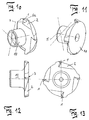
- All milling tools shown in the figures have on their Circumferentially evenly spaced blades 1 and each one - seen in the direction of rotation - arranged in front of each cutting edge 1 Spanraum 2 on that for receiving and deriving the from the trailing cutting edge 1 cut chips is used.
- the Tool body 11, in which the chip spaces 2 are formed goes in the axial direction into a flange 12, by means of which the Milling tool with a drive shaft not shown here is connectable.
- the flange 12 is hollow (see Figures 1 and 10).
- the chip space 2 is in the direction of the tool axis 5 considered closed on one side by the tool body 11 brought up to the cutting edge 1 on its end face 3 is.
- the limitation of the chip space 2 by the design the end face 3 of the tool body 11 does not run in one plane, but tapers the chip space 2 in the direction of rotation (see Figures 1 and 10).
- the chip space extends over the axial width b of the Tool and opens in its two end faces 3, 4 open out.
- the Cut 1 an acute cutting line angle with the tool axis 5 ⁇ including cutting line 6.
- the chip space reason 7 has a cutting line which is oblique with respect to this 6 opposite inclination with the cutting line 6 includes an acute bottom angle ⁇ that is greater than that called cutting line angle ⁇ .
- the bottom of the chip space runs 7 straight across the axial tool width b.
- the schematic Representation in Figure 6 shows that the radial Depth of the chip space 2 - based on the cutting edge 1 - of one Minimum value on the right side 3 in FIG. 2 to one Maximum value on the left end face 4 increases.
- FIG. 7 shows a profile milling cutter in a representation according to FIG. 6, whose curved cutting edge 1 one Inclined section 6a, during the formation of the chip space 2 corresponds to Figure 2.
- Figure 8 also shows a profile cutter, in which the chip space base 7 curve-shaped over the axial tool width b runs, the chip space 7 at least in some areas opposite to the inclined section 6a of the cutting edge 1 Inclination with the cutting bevel section 6a includes an acute bottom angle ⁇ that is greater than that Cutting line angle ⁇ .
- the cutting line angle ⁇ can be very be small and tend towards zero. In case of an exception it can be zero if a non-profiled cutting edge is used becomes.
- FIG. 9 essentially corresponds to that of FIG. 8 with regard to the cutting edge 1 and the chip space base 7, but the chip space base 7, which runs in a curve over the axial tool width b, has a decreasing inclination towards the deeper chip space side (left end face 4).
- the chip space 2 on the tool face 3, which has the largest diameter D max of the chip space base 7, is covered by a preferably screwed washer 8 connected to the tool, so that the one with the exemplary embodiments according to FIGS. 1 to 4 and 10 to 13 related benefits can be obtained.
- the chips are captured outside the tool rotation level.
- the chip detection device (not shown here) can be arranged axially offset from the tool and the cutting edges 1 can freely engage the workpiece over the entire tool circumference.
- the emerging chip stream can be enclosed on all sides by a detection element (not shown). This means that the chips can be completely captured. If the chips generated during work are to be extracted, the suction opening of the chip detection element can be arranged exactly in the direction of the emerging chip stream. Because the chips no longer have to be redirected by the suction air, a comparatively low suction capacity can be used.
- the chip exit does not take place circumferentially in the plane of rotation of the cutting edges 1, but along an axially aligned conical surface between the plane of rotation and the tool axis 5, which favors the chip spaces 2 which are axially closed towards one end side 3 and wide open towards the other end side 4 becomes.
- Figure 5 illustrates the machining of a workpiece 9 by a profile milling cutter 10, the arrows shown the derivation of the cut from the trailing edge Indicate chips.
Landscapes
- Life Sciences & Earth Sciences (AREA)
- Engineering & Computer Science (AREA)
- Mechanical Engineering (AREA)
- Wood Science & Technology (AREA)
- Forests & Forestry (AREA)
- Milling Processes (AREA)
- Drilling Tools (AREA)
- Magnetic Heads (AREA)
- Shovels (AREA)
Abstract
Description
- Figuren 1 bis 4 -
- ein als Abrundwerkzeug vorgesehenes Fräswerkzeug mit einseitig geschlossenem Spanraum in verschiedenen Ansichten;
- Figur 5 -
- die obere Hälfte eines Profilfräsers mit anliegendem Werkstück;
- Figuren 6 bis 9 -
- vier unterschiedliche Fräserformen in einer Darstellung gemäß Figur 5;
- Figuren 10 bis 13 -
- ein als Fasewerkzeug verwendbares Fräswerkzeug mit einseitig geschlossenem Spanraum in verschiedenen Ansichten.
- 1
- Schneide
- 2
- Spanraum
- 3
- Stirnseite
- 4
- Stirnseite
- 5
- Werkzeugachse
- 6
- Schneidenlinie
- 6a
- Schrägabschnitt
- 7
- Spanraumgrund
- 8
- Scheibe
- 9
- Werkstück
- 10
- Profilfräser
- 11
- Werkzeugkörper
- 12
- Flansch
Claims (8)
- Fräswerkzeug für die spanende Bearbeitung von Holz, Holzwerkstoffen oder Kunststoff, insbesondere Umfangsfräser oder Profilfräser, mit an seinem Umfang gleichmäßig versetzt angeordneten Schneiden (1) und mit jeweils einem - in Umlaufrichtung gesehen - vor jeder Schneide (1) angeordneten Spanraum (2) zur Aufnahme und Ableitung der von der nacheilenden Schneide (1) abgeschnittenen Späne, dadurch gekennzeichnet, dass jede Schneide (1) zumindest einen mit der Werkzeugachse (5) einen spitzen Schneidenlinienwinkel (α) einschließenden Schrägabschnitt (6a) aufweist, und dass der Spanraumgrund (7) zumindest bereichsweise eine gegenüber diesem Schrägabschnitt (6a) entgegengerichtete Neigung aufweist, die mit dem Schneiden-Schrägabschnitt (6a) einen spitzen Bodenwinkel (β) einschließt, der größer ist als der genannte Schneidenlinienwinkel (α).
- Fräswerkzeug nach Anspruch 1, dadurch gekennzeichnet, dass der Spanraum (2) an einer seiner Stirnseiten (3) geschlossen ist.
- Fräswerkzeug nach Anspruch 1, dadurch gekennzeichnet, dass sich der Spanraum (2) über die axiale Werkzeugbreite (b) erstreckt und in dessen beiden Stirnseiten (3, 4) offen ausmündet.
- Fräswerkzeug nach Anspruch 3, dadurch gekennzeichnet, dass der Spanraumgrund (7) über die axiale Werkzeugbreite (b) geradlinig verläuft. (Figur 6)
- Fräswerkzeug nach einem der Ansprüche 1 bis 4, dadurch gekennzeichnet, dass der Spanraumgrund (7) über die axiale Werkzeugbreite (b) kurvenlinienförmig verläuft mit einer zur tieferen Spanraumseite hin abnehmenden Neigung. (Figur 9)
- Fräswerkzeug nach einem der Ansprüche 3 bis 5, dadurch gekennzeichnet, dass der Durchmesser (Dmax) des radial höchsten Spanraumgrundes (7) gleich dem oder nur etwas kleiner ist als der Durchmesser (DS) der in dieser Werkzeug-Stirnseite (3) ausmündenden Schneide (1).
- Fräswerkzeug nach Anspruch 2, dadurch gekennzeichnet, dass der Spanraum (2) auf der den größten Durchmesser (Dmax) des Spanraumgrundes (7) aufweisenden Werkzeug-Stirnseite (3) durch eine mit dem Werkzeug verbundene Scheibe (8) abgedeckt ist.
- Fräswerkzeug nach Anspruch 1, dadurch gekennzeichnet, dass der Schneidenlinienwinkel (α) gegen Null läuft oder gleich Null ist.
Priority Applications (1)
| Application Number | Priority Date | Filing Date | Title |
|---|---|---|---|
| DE20019885U DE20019885U1 (de) | 2000-05-16 | 2000-11-22 | Fräswerkzeug mit schrägen Spanräumen |
Applications Claiming Priority (2)
| Application Number | Priority Date | Filing Date | Title |
|---|---|---|---|
| DE29914278U | 1999-08-14 | ||
| DE29914278U DE29914278U1 (de) | 1999-08-14 | 1999-08-14 | Fräswerkzeug |
Publications (3)
| Publication Number | Publication Date |
|---|---|
| EP1077121A2 true EP1077121A2 (de) | 2001-02-21 |
| EP1077121A3 EP1077121A3 (de) | 2003-04-09 |
| EP1077121B1 EP1077121B1 (de) | 2006-04-12 |
Family
ID=8077550
Family Applications (1)
| Application Number | Title | Priority Date | Filing Date |
|---|---|---|---|
| EP00110412A Expired - Lifetime EP1077121B1 (de) | 1999-08-14 | 2000-05-16 | Fräswerkzeug |
Country Status (6)
| Country | Link |
|---|---|
| EP (1) | EP1077121B1 (de) |
| AT (1) | ATE322963T1 (de) |
| DE (2) | DE29914278U1 (de) |
| DK (1) | DK1077121T3 (de) |
| ES (1) | ES2261119T3 (de) |
| PT (1) | PT1077121E (de) |
Cited By (2)
| Publication number | Priority date | Publication date | Assignee | Title |
|---|---|---|---|---|
| DE102011107661A1 (de) | 2011-07-12 | 2013-01-17 | Hans-Jürgen Gittel | Werkzeug zum Kappen |
| CN109434982A (zh) * | 2018-12-19 | 2019-03-08 | 天津广顺锐林木工刀具科技有限公司 | 一种用于木门的组合式花形铣刀 |
Families Citing this family (1)
| Publication number | Priority date | Publication date | Assignee | Title |
|---|---|---|---|---|
| ES2340894B1 (es) * | 2007-03-09 | 2011-04-13 | Casals Herramientas Electricas, S.L. | Herramienta para cortar tableros de madera. |
Family Cites Families (4)
| Publication number | Priority date | Publication date | Assignee | Title |
|---|---|---|---|---|
| US4984614A (en) * | 1990-03-08 | 1991-01-15 | Hi-Tech Engineering And Machine Company, Inc. | Combined saw and chipper head |
| DE4419026A1 (de) * | 1994-05-31 | 1995-12-07 | Marcus Koeppl | Werkzeug zur maschinellen spanabhebenden Bearbeitung von Holz |
| DE19626158C2 (de) * | 1996-06-28 | 1998-04-23 | Schrammel Helmut Dipl Ing Fh | Fräseinheit |
| DE29906758U1 (de) * | 1999-02-19 | 1999-07-15 | Technische Universität Dresden, 01069 Dresden | Fräswerkzeug zur spanenden Bearbeitung von Holz, Holzwerkstoff, Kunststoff o.dgl. |
-
1999
- 1999-08-14 DE DE29914278U patent/DE29914278U1/de not_active Expired - Lifetime
-
2000
- 2000-05-16 DE DE50012556T patent/DE50012556D1/de not_active Expired - Lifetime
- 2000-05-16 DK DK00110412T patent/DK1077121T3/da active
- 2000-05-16 PT PT00110412T patent/PT1077121E/pt unknown
- 2000-05-16 EP EP00110412A patent/EP1077121B1/de not_active Expired - Lifetime
- 2000-05-16 ES ES00110412T patent/ES2261119T3/es not_active Expired - Lifetime
- 2000-05-16 AT AT00110412T patent/ATE322963T1/de active
Cited By (2)
| Publication number | Priority date | Publication date | Assignee | Title |
|---|---|---|---|---|
| DE102011107661A1 (de) | 2011-07-12 | 2013-01-17 | Hans-Jürgen Gittel | Werkzeug zum Kappen |
| CN109434982A (zh) * | 2018-12-19 | 2019-03-08 | 天津广顺锐林木工刀具科技有限公司 | 一种用于木门的组合式花形铣刀 |
Also Published As
| Publication number | Publication date |
|---|---|
| PT1077121E (pt) | 2006-08-31 |
| DE29914278U1 (de) | 2000-12-28 |
| DK1077121T3 (da) | 2006-07-31 |
| EP1077121B1 (de) | 2006-04-12 |
| ES2261119T3 (es) | 2006-11-16 |
| ATE322963T1 (de) | 2006-04-15 |
| DE50012556D1 (de) | 2006-05-24 |
| EP1077121A3 (de) | 2003-04-09 |
Similar Documents
| Publication | Publication Date | Title |
|---|---|---|
| DE3932345C3 (de) | Zerkleinerungsvorrichtung für Abfälle | |
| DE3854408T2 (de) | Holzbearbeitungswerkzeug. | |
| EP4201588A1 (de) | Fräswerkzeug für eine dentalfräsmaschine und anordnung aus einer frässpindel und einem fräswerkzeug | |
| DE3632296A1 (de) | Gewinde-fraeswerkzeug | |
| EP1077121B1 (de) | Fräswerkzeug | |
| DE1302331C2 (de) | Werkzeugkopf zum abspanen der seitenflaechen von rundholzstaemmen | |
| EP0807500B1 (de) | Zerspaner für Hackschnitzel | |
| DE19950722B4 (de) | Fräswerkzeug zur spanenden Bearbeitung von Holz, Holzwerkstoff, Kunststoff o. dgl. | |
| DE19545084C1 (de) | Drehantreibbares Werkzeug | |
| DE3824348A1 (de) | Fraeskopf | |
| CH653284A5 (en) | Cutting tool for the profile cutting of round timber | |
| CH682470A5 (de) | Fräswerkzeug. | |
| DE19654421B4 (de) | Messerplatte für ein Werkzeug zur spanabhebenden Feinbearbeitung | |
| DE3317409A1 (de) | Vorrichtung zum absaugen von spaenen | |
| WO2018041436A1 (de) | Einschneidiges fräswerkzeug | |
| DE9314616U1 (de) | Formfräser | |
| DE3318844C2 (de) | ||
| DE29519102U1 (de) | Rotierendes Werkzeug | |
| DE3509753A1 (de) | Drehendes schneidwerkzeug | |
| DE2037241B2 (de) | Fraeser | |
| DE102013004394A1 (de) | Schneidplatte und Fräswerkzeug mit Schneidplatte | |
| EP1415777A1 (de) | Bearbeitungswerkzeug | |
| DE2142972A1 (de) | Rotierendes schneidwerkzeug | |
| DE10239221B4 (de) | Hobel-Werkzeug mit mehreren Schneiden zum Bearbeiten planer Oberflächen | |
| DE2037241C (de) | Fräser |
Legal Events
| Date | Code | Title | Description |
|---|---|---|---|
| PUAI | Public reference made under article 153(3) epc to a published international application that has entered the european phase |
Free format text: ORIGINAL CODE: 0009012 |
|
| AK | Designated contracting states |
Kind code of ref document: A2 Designated state(s): AT BE CH CY DE DK ES FI FR GB GR IE IT LI LU MC NL PT SE |
|
| AX | Request for extension of the european patent |
Free format text: AL;LT;LV;MK;RO;SI |
|
| PUAL | Search report despatched |
Free format text: ORIGINAL CODE: 0009013 |
|
| AK | Designated contracting states |
Kind code of ref document: A3 Designated state(s): AT BE CH CY DE DK ES FI FR GB GR IE IT LI LU MC NL PT SE |
|
| AX | Request for extension of the european patent |
Extension state: AL LT LV MK RO SI |
|
| 17P | Request for examination filed |
Effective date: 20031007 |
|
| AKX | Designation fees paid |
Designated state(s): AT BE CH CY DE DK ES FI FR GB GR IE IT LI LU MC NL PT SE |
|
| 17Q | First examination report despatched |
Effective date: 20041220 |
|
| GRAP | Despatch of communication of intention to grant a patent |
Free format text: ORIGINAL CODE: EPIDOSNIGR1 |
|
| GRAS | Grant fee paid |
Free format text: ORIGINAL CODE: EPIDOSNIGR3 |
|
| GRAA | (expected) grant |
Free format text: ORIGINAL CODE: 0009210 |
|
| RAP1 | Party data changed (applicant data changed or rights of an application transferred) |
Owner name: LEITZ GMBH & CO. KG |
|
| AK | Designated contracting states |
Kind code of ref document: B1 Designated state(s): AT BE CH CY DE DK ES FI FR GB GR IE IT LI LU MC NL PT SE |
|
| PG25 | Lapsed in a contracting state [announced via postgrant information from national office to epo] |
Ref country code: NL Free format text: LAPSE BECAUSE OF FAILURE TO SUBMIT A TRANSLATION OF THE DESCRIPTION OR TO PAY THE FEE WITHIN THE PRESCRIBED TIME-LIMIT Effective date: 20060412 Ref country code: IE Free format text: LAPSE BECAUSE OF FAILURE TO SUBMIT A TRANSLATION OF THE DESCRIPTION OR TO PAY THE FEE WITHIN THE PRESCRIBED TIME-LIMIT Effective date: 20060412 Ref country code: FI Free format text: LAPSE BECAUSE OF FAILURE TO SUBMIT A TRANSLATION OF THE DESCRIPTION OR TO PAY THE FEE WITHIN THE PRESCRIBED TIME-LIMIT Effective date: 20060412 Ref country code: GB Free format text: LAPSE BECAUSE OF FAILURE TO SUBMIT A TRANSLATION OF THE DESCRIPTION OR TO PAY THE FEE WITHIN THE PRESCRIBED TIME-LIMIT Effective date: 20060412 |
|
| REG | Reference to a national code |
Ref country code: GB Ref legal event code: FG4D Free format text: NOT ENGLISH |
|
| REG | Reference to a national code |
Ref country code: CH Ref legal event code: EP |
|
| REF | Corresponds to: |
Ref document number: 50012556 Country of ref document: DE Date of ref document: 20060524 Kind code of ref document: P |
|
| PG25 | Lapsed in a contracting state [announced via postgrant information from national office to epo] |
Ref country code: MC Free format text: LAPSE BECAUSE OF NON-PAYMENT OF DUE FEES Effective date: 20060531 Ref country code: BE Free format text: LAPSE BECAUSE OF NON-PAYMENT OF DUE FEES Effective date: 20060531 |
|
| REG | Reference to a national code |
Ref country code: IE Ref legal event code: FG4D Free format text: LANGUAGE OF EP DOCUMENT: GERMAN |
|
| REG | Reference to a national code |
Ref country code: SE Ref legal event code: TRGR |
|
| REG | Reference to a national code |
Ref country code: CH Ref legal event code: NV Representative=s name: BRAUNPAT BRAUN EDER AG Ref country code: DK Ref legal event code: T3 |
|
| REG | Reference to a national code |
Ref country code: PT Ref legal event code: SC4A Effective date: 20060710 |
|
| NLV1 | Nl: lapsed or annulled due to failure to fulfill the requirements of art. 29p and 29m of the patents act | ||
| GBV | Gb: ep patent (uk) treated as always having been void in accordance with gb section 77(7)/1977 [no translation filed] |
Effective date: 20060412 |
|
| REG | Reference to a national code |
Ref country code: IE Ref legal event code: FD4D |
|
| REG | Reference to a national code |
Ref country code: ES Ref legal event code: FG2A Ref document number: 2261119 Country of ref document: ES Kind code of ref document: T3 |
|
| PLBE | No opposition filed within time limit |
Free format text: ORIGINAL CODE: 0009261 |
|
| STAA | Information on the status of an ep patent application or granted ep patent |
Free format text: STATUS: NO OPPOSITION FILED WITHIN TIME LIMIT |
|
| 26N | No opposition filed |
Effective date: 20070115 |
|
| EN | Fr: translation not filed | ||
| BERE | Be: lapsed |
Owner name: LEITZ G.M.B.H. & CO. KG Effective date: 20060531 |
|
| PG25 | Lapsed in a contracting state [announced via postgrant information from national office to epo] |
Ref country code: GR Free format text: LAPSE BECAUSE OF FAILURE TO SUBMIT A TRANSLATION OF THE DESCRIPTION OR TO PAY THE FEE WITHIN THE PRESCRIBED TIME-LIMIT Effective date: 20060713 Ref country code: FR Free format text: LAPSE BECAUSE OF FAILURE TO SUBMIT A TRANSLATION OF THE DESCRIPTION OR TO PAY THE FEE WITHIN THE PRESCRIBED TIME-LIMIT Effective date: 20070309 |
|
| PG25 | Lapsed in a contracting state [announced via postgrant information from national office to epo] |
Ref country code: LU Free format text: LAPSE BECAUSE OF NON-PAYMENT OF DUE FEES Effective date: 20060516 |
|
| PG25 | Lapsed in a contracting state [announced via postgrant information from national office to epo] |
Ref country code: FR Free format text: LAPSE BECAUSE OF FAILURE TO SUBMIT A TRANSLATION OF THE DESCRIPTION OR TO PAY THE FEE WITHIN THE PRESCRIBED TIME-LIMIT Effective date: 20060531 |
|
| PG25 | Lapsed in a contracting state [announced via postgrant information from national office to epo] |
Ref country code: CY Free format text: LAPSE BECAUSE OF FAILURE TO SUBMIT A TRANSLATION OF THE DESCRIPTION OR TO PAY THE FEE WITHIN THE PRESCRIBED TIME-LIMIT Effective date: 20060412 Ref country code: FR Free format text: LAPSE BECAUSE OF FAILURE TO SUBMIT A TRANSLATION OF THE DESCRIPTION OR TO PAY THE FEE WITHIN THE PRESCRIBED TIME-LIMIT Effective date: 20060412 |
|
| PGFP | Annual fee paid to national office [announced via postgrant information from national office to epo] |
Ref country code: AT Payment date: 20110520 Year of fee payment: 12 |
|
| PGFP | Annual fee paid to national office [announced via postgrant information from national office to epo] |
Ref country code: ES Payment date: 20120525 Year of fee payment: 13 |
|
| REG | Reference to a national code |
Ref country code: AT Ref legal event code: MM01 Ref document number: 322963 Country of ref document: AT Kind code of ref document: T Effective date: 20120516 |
|
| PG25 | Lapsed in a contracting state [announced via postgrant information from national office to epo] |
Ref country code: AT Free format text: LAPSE BECAUSE OF NON-PAYMENT OF DUE FEES Effective date: 20120516 |
|
| PGFP | Annual fee paid to national office [announced via postgrant information from national office to epo] |
Ref country code: SE Payment date: 20130521 Year of fee payment: 14 Ref country code: DK Payment date: 20130522 Year of fee payment: 14 Ref country code: CH Payment date: 20130522 Year of fee payment: 14 |
|
| PGFP | Annual fee paid to national office [announced via postgrant information from national office to epo] |
Ref country code: PT Payment date: 20130513 Year of fee payment: 14 |
|
| PGFP | Annual fee paid to national office [announced via postgrant information from national office to epo] |
Ref country code: IT Payment date: 20140520 Year of fee payment: 15 |
|
| REG | Reference to a national code |
Ref country code: PT Ref legal event code: MM4A Free format text: LAPSE DUE TO NON-PAYMENT OF FEES Effective date: 20141117 |
|
| REG | Reference to a national code |
Ref country code: CH Ref legal event code: PL |
|
| REG | Reference to a national code |
Ref country code: DK Ref legal event code: EBP Effective date: 20140531 |
|
| PG25 | Lapsed in a contracting state [announced via postgrant information from national office to epo] |
Ref country code: PT Free format text: LAPSE BECAUSE OF NON-PAYMENT OF DUE FEES Effective date: 20141117 Ref country code: CH Free format text: LAPSE BECAUSE OF NON-PAYMENT OF DUE FEES Effective date: 20140531 Ref country code: LI Free format text: LAPSE BECAUSE OF NON-PAYMENT OF DUE FEES Effective date: 20140531 Ref country code: SE Free format text: LAPSE BECAUSE OF NON-PAYMENT OF DUE FEES Effective date: 20140517 |
|
| REG | Reference to a national code |
Ref country code: SE Ref legal event code: EUG |
|
| PG25 | Lapsed in a contracting state [announced via postgrant information from national office to epo] |
Ref country code: DK Free format text: LAPSE BECAUSE OF NON-PAYMENT OF DUE FEES Effective date: 20140531 |
|
| REG | Reference to a national code |
Ref country code: ES Ref legal event code: FD2A Effective date: 20150630 |
|
| PG25 | Lapsed in a contracting state [announced via postgrant information from national office to epo] |
Ref country code: ES Free format text: LAPSE BECAUSE OF NON-PAYMENT OF DUE FEES Effective date: 20140517 |
|
| PGFP | Annual fee paid to national office [announced via postgrant information from national office to epo] |
Ref country code: DE Payment date: 20150601 Year of fee payment: 16 |
|
| REG | Reference to a national code |
Ref country code: DE Ref legal event code: R082 Ref document number: 50012556 Country of ref document: DE Representative=s name: GRAMM, LINS & PARTNER PATENT- UND RECHTSANWAEL, DE |
|
| PG25 | Lapsed in a contracting state [announced via postgrant information from national office to epo] |
Ref country code: IT Free format text: LAPSE BECAUSE OF NON-PAYMENT OF DUE FEES Effective date: 20150516 |
|
| REG | Reference to a national code |
Ref country code: DE Ref legal event code: R119 Ref document number: 50012556 Country of ref document: DE |
|
| PG25 | Lapsed in a contracting state [announced via postgrant information from national office to epo] |
Ref country code: DE Free format text: LAPSE BECAUSE OF NON-PAYMENT OF DUE FEES Effective date: 20161201 |