EP1077164B1 - Wischerlager - Google Patents
Wischerlager Download PDFInfo
- Publication number
- EP1077164B1 EP1077164B1 EP00115259A EP00115259A EP1077164B1 EP 1077164 B1 EP1077164 B1 EP 1077164B1 EP 00115259 A EP00115259 A EP 00115259A EP 00115259 A EP00115259 A EP 00115259A EP 1077164 B1 EP1077164 B1 EP 1077164B1
- Authority
- EP
- European Patent Office
- Prior art keywords
- component
- teeth
- drive shaft
- height
- edges
- Prior art date
- Legal status (The legal status is an assumption and is not a legal conclusion. Google has not performed a legal analysis and makes no representation as to the accuracy of the status listed.)
- Expired - Lifetime
Links
- 239000000463 material Substances 0.000 claims description 27
- 229910000831 Steel Inorganic materials 0.000 claims description 6
- 229910052782 aluminium Inorganic materials 0.000 claims description 6
- XAGFODPZIPBFFR-UHFFFAOYSA-N aluminium Chemical compound [Al] XAGFODPZIPBFFR-UHFFFAOYSA-N 0.000 claims description 6
- 239000004033 plastic Substances 0.000 claims description 6
- 239000010959 steel Substances 0.000 claims description 6
- FYYHWMGAXLPEAU-UHFFFAOYSA-N Magnesium Chemical compound [Mg] FYYHWMGAXLPEAU-UHFFFAOYSA-N 0.000 claims description 5
- HCHKCACWOHOZIP-UHFFFAOYSA-N Zinc Chemical compound [Zn] HCHKCACWOHOZIP-UHFFFAOYSA-N 0.000 claims description 5
- 229910052749 magnesium Inorganic materials 0.000 claims description 5
- 239000011777 magnesium Substances 0.000 claims description 5
- 229910052725 zinc Inorganic materials 0.000 claims description 5
- 239000011701 zinc Substances 0.000 claims description 5
- 230000003247 decreasing effect Effects 0.000 claims description 3
- 239000004411 aluminium Substances 0.000 claims 2
- 238000005520 cutting process Methods 0.000 description 6
- 238000000034 method Methods 0.000 description 2
- 241000237942 Conidae Species 0.000 description 1
- 230000007423 decrease Effects 0.000 description 1
- 238000001125 extrusion Methods 0.000 description 1
- 210000003127 knee Anatomy 0.000 description 1
- 210000000629 knee joint Anatomy 0.000 description 1
- 238000003754 machining Methods 0.000 description 1
- 238000004519 manufacturing process Methods 0.000 description 1
- 229910052751 metal Inorganic materials 0.000 description 1
- 239000002184 metal Substances 0.000 description 1
- 238000003801 milling Methods 0.000 description 1
- 238000005096 rolling process Methods 0.000 description 1
- 238000007493 shaping process Methods 0.000 description 1
Images


Classifications
-
- B—PERFORMING OPERATIONS; TRANSPORTING
- B60—VEHICLES IN GENERAL
- B60S—SERVICING, CLEANING, REPAIRING, SUPPORTING, LIFTING, OR MANOEUVRING OF VEHICLES, NOT OTHERWISE PROVIDED FOR
- B60S1/00—Cleaning of vehicles
- B60S1/02—Cleaning windscreens, windows or optical devices
- B60S1/04—Wipers or the like, e.g. scrapers
- B60S1/32—Wipers or the like, e.g. scrapers characterised by constructional features of wiper blade arms or blades
- B60S1/34—Wiper arms; Mountings therefor
-
- B—PERFORMING OPERATIONS; TRANSPORTING
- B60—VEHICLES IN GENERAL
- B60S—SERVICING, CLEANING, REPAIRING, SUPPORTING, LIFTING, OR MANOEUVRING OF VEHICLES, NOT OTHERWISE PROVIDED FOR
- B60S1/00—Cleaning of vehicles
- B60S1/02—Cleaning windscreens, windows or optical devices
- B60S1/04—Wipers or the like, e.g. scrapers
- B60S1/32—Wipers or the like, e.g. scrapers characterised by constructional features of wiper blade arms or blades
- B60S1/34—Wiper arms; Mountings therefor
- B60S1/3488—Means for mounting wiper arms onto the vehicle
- B60S1/3493—Means for mounting the wiper shaft in the wiper bearing
Definitions
- the invention is based on a wiper bearing according to the preamble of claim 1, see US 5699582 A.
- the board carries a wiper drive with a wiper motor, whose motor shaft drives cranks via a linkage, the one end of a drive shaft for everyone Wipers are firmly connected. It is also possible that only the drive shaft of a wiper from the wiper motor is driven while another wiper is over a four-bar linkage with the first wiper is connected and has a bearing axis.
- the drive shaft or the bearing axis is stored in a wiper bearing. in the The following is a description of a drive shaft for a bearing axis, which is no longer expressly mentioned becomes.
- the bearing housing is at least one radial bearing and to the End faces between the bearing housing and one with the drive shaft firmly connected part provided an axial bearing.
- the drive shaft protrudes from the body and moves you wiper arm fastened at its free end with a Wiper blade over a windshield.
- the wiper arm has usually one that is connected to the drive shaft in a rotationally fixed manner Fastening part that is articulated with a joint part is to which a wiper rod rigidly connects. Further it is possible that the wiper arm is not directly connected to the drive shaft is connected, but with a lever gear driven on the drive shaft rotatably connected drive lever becomes.
- the following explanations on the connection of the fastening part with the drive shaft also apply to a drive lever that is no longer specifically mentioned becomes.
- the fastening part instructs one end of a bearing with an inner cone with which the fastening part when assembling the wiper arm in one first assembly step on a correspondingly shaped outer cone the drive shaft is placed. Then in a second assembly step on the drive shaft a nut screwed, over which the fastening part with the inner cone is pressed onto the outer cone of the drive shaft.
- knurled teeth on the cone of the drive shaft or to form knurled edges is known.
- the extent depends on Diameter of the drive shaft 29 to 44 knurled blades arranged, aligned in the longitudinal direction of the drive shaft are and a triangular cross-sectional area with an angle of 90 °.
- the height and cross-sectional area of the Knurled cutting increases with increasing cone diameter too, so that the entire lateral surface of the cone is knurled is covered.
- the wiper bearing according to the invention has a drive shaft, the via at least one cone connection between a first and a second component directly or indirectly with a Wiper arm is connected.
- the first component is made of a harder one Material made as the second component and owns Teeth formed on the surface of the cone.
- the teeth will pressed into the second component when installing the wiper arm and create a positive connection in addition to a frictional connection between the first and the second component, wherein the height of the teeth, i.e. from the tooth base to the tip of the tooth, constant over the surface of the cone is.
- the teeth deform the material during assembly of the second component evenly.
- the second component can with a small tightening torque of a fastening nut or with a small axial force on the entire surface of the cone of the first component to be brought to rest.
- Inserts, especially in plastic fasteners, can be avoided become.
- inexpensive materials with low Wall thicknesses can be used.
- the invention is characterized in that with several teeth arranged offset in the longitudinal direction the distance between two in the circumferential direction teeth arranged at the same height and the form fit improved or a high permissible transferable Torque is reached.
- the teeth can be made with different ones that are suitable to the skilled person appearing methods are molded, such as through non-cutting primary shaping or forming, such as rolling with one Knurling tool, extrusion, deep drawing in sheet metal Components or by machining processes such as milling, Broaching, etc. Furthermore, the teeth can have different shapes, such as pyramid-shaped, conical, etc. In one embodiment of the invention it is proposed that the teeth of substantially longitudinally aligned Cutting edges are formed which are constant in the longitudinal direction Height and preferably a constant cross-sectional area exhibit. Longitudinally aligned Cutting edges can be produced particularly inexpensively and bring about a good form fit.
- a cone connection can be made with the teeth according to the invention between any components between the drive shaft and the wiper arm can be improved, such as between a thrust piece that is form-fitting on the drive shaft is attached and with an outer cone over a corresponding shaped inner cone of a fastening part a drive torque transfers to the wiper arm.
- the first component is formed by the drive shaft or the drive shaft has a cone with molded Teeth. Additional components, assembly effort and costs can be saved and in particular series components can be used inexpensively in large quantities getting produced.
- the wiper arm can be used with a conventional Assembly method is attached to the drive shaft in a particularly rotationally fixed manner become.
- the distance in the circumferential direction between two teeth at the same axial height on the first Component on the tensile strength of the materials used matched for the first component and for the second component and with decreasing tensile strength of the material for the second component relative to the tensile strength of the material for the first component increases.
- the shear strength of the teeth on the first component and the material between the teeth of the second component can be matched to one another and overall the greatest possible Shear strength and the greatest possible transferable torque can be achieved. With a larger circumferential distance can have fewer teeth with the same diameter be attached to the cone.
- the one according to DIN Has a surface hardness of at least 135 HBS to 200 HBS, are advantageous for a second component made of steel 30 to 40 blades with a height of 0.8 to 1.0 mm, with one second component made of zinc or aluminum 20 to 30 cutting edges with a height of 0.7 to 1.1 mm, with a second component made of magnesium 15 to 25 blades with a height of 0.7 to 1.1 mm and 5 to 15 for a second plastic component Cut with a height of 0.7 to 2.0 mm over the circumference molded on the conical surface on the drive shaft.
- For drive shafts with a smaller or a larger nominal diameter are correspondingly fewer or more cutting edges arranged over the circumference.
- the permissible maximum loads in the circumferential direction of teeth and that between teeth Material of the second component matched to one another total maximum permissible transmittable torque reached become.
- Fig. 1 shows a section of a wiper system 36 for a Motor vehicle, the wiper bearing on a board 38 on the Body 40 of the motor vehicle are attached.
- the circuit board 38 carries a wiper drive with a wiper motor 42, the Motor shaft 44 via a crank 46 and not closer Linkage shown drives cranks 48, each with one end of a drive shaft 10 for a wiper are firmly connected.
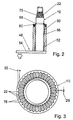
- the drive shaft 10 is in a bearing housing 56 of the wiper bearing radially via bearing bushes 50, 52 and in a first axial direction via a crank arm 54 and in a second axial direction via a clamping ring 58 and a race 60 is mounted (Fig. 2).
- the drive shaft 10 protrudes from the body 40 and moves one on its free End attached wiper arm 20 with a not shown Wiper blade over a windshield (Fig. 1).
- the Wiper arm 20 is with a fastening part 18 via a cone connection 16 attached to the drive shaft 10.
- the fastener 18 is articulated with a via a knee joint 62 Joint part 64 connected to the rigidly a wiper rod 66 connects. In the wiper rod 66 is on a bow-shaped The wiper blade hooked in at the end of 68.
- the drive shaft 10 is made of a harder material than that Fastening part 18 and has an outer cone 70 in Teeth or knurled blades aligned in the longitudinal direction 22, when mounting the fastening part 18 on the drive shaft 10 in a lateral surface of an inner cone 72 of Fastening part 18 are pressed and next to a frictional connection a positive connection between the drive shaft 10 and the Manufacture fastening part 18 (Fig. 1, 2 and 3).
- the knurled blades 22 have one in the longitudinal direction constant height 32, i.e. from the tooth base to the tooth tip, are equal to each other and preferably have a constant cross-sectional area. Between the knurled edges 22 result in smooth conical outer surfaces 76.
- the material of the fastening part 18 uniformly deformed over the length of the knurled edges 22.
- the fastening part 18 can be tightened with a small torque a fastening nut 74 or with a small axial Force on the entire surface of the cone of the drive shaft 10 to be brought to rest. Only a partial edition of the Fastening part 18 on the tips of the knurled blades 22, in particular at the lower area of the outer cone 70, is avoided and there is a good force and form fit between the drive shaft 10 and the fastening part 18 reached.
- a drive shaft 12 with knurled blades 24 shown for a fastener made of one material is made with a lower tensile strength than that Fastening part 18, namely for a fastening part Aluminum or magnesium.
- the distance 30 between the knurled edges 24 is greater than the distance 28 between the knurled edges 22 in the embodiment in Fig. 3.
- the shear strength of the knurled edges 24 the drive shaft 12 and that between the knurled blades 24 standing material of the fastening part are aligned, so that overall the greatest possible shear strength and the greatest possible permissible transferable torque is achieved.
- the knurled edges 24 also have a greater height 34 than the knurled edges 22.
- the knurled edges 24 in the longitudinal direction have the knurled blades 24 in the longitudinal direction a constant height 34 and a constant Cross sectional area.
- FIG. 5 shows a drive shaft 14 with several in the longitudinal direction offset knurled edges 26.
- knurled edges 26 each arranged between two at the same axial height in the circumferential direction Knurling 26 reaches a large distance 78 and especially with fasteners made of materials low tensile strengths, high torque are transmitted, without the material of the fastening part being sheared off is, for example aluminum, zinc, magnesium, plastic etc.
- the knurled blades are 26 rounded in the direction of the fastening part (Fig. 6).
Landscapes
- Engineering & Computer Science (AREA)
- Mechanical Engineering (AREA)
- Sliding-Contact Bearings (AREA)
Description
- Fig. 1
- einen Ausschnitt einer Wischeranlage mit einem Wischarm im Schnitt,
- Fig. 2
- einen Schnitt entlang der Linie II-II in Fig. 1 ohne Befestigungsteil,
- Fig. 3
- eine vergrößerte Ansicht einer Antriebswelle von oben,
- Fig. 4
- eine Variante nach Fig. 3 für ein zweites Bauteil aus einem Material mit einer geringen Zugfestigkeit,
- Fig. 5
- eine Variante nach Fig. 3 mit versetzt angeordneten Rändelschneiden und dies in Übereinstimmung mit der Erfindung
- Fig. 6
- einen vergrößerten Ausschnitt VI in Fig. 5.
- 10
- Antriebswelle
- 12
- Antriebswelle
- 14
- Antriebswelle
- 16
- Konusverbindung
- 18
- Bauteil
- 20
- Wischarm
- 22
- Zahn
- 24
- Zahn
- 26
- Zahn
- 28
- Abstand
- 30
- Abstand
- 32
- Höhe
- 34
- Höhe
- 36
- Wischeranlage
- 38
- Platine
- 40
- Karosserie
- 42
- Wischermotor
- 44
- Motorwelle
- 46
- Kurbel
- 48
- Kurbel
- 50
- Lagerbuchse
- 52
- Lagerbuchse
- 54
- Kurbelarm
- 56
- Lagergehäuse
- 58
- Spannring
- 60
- Laufring
- 62
- Kniegelenk
- 64
- Gelenkteil
- 66
- Wischstange
- 68
- Ende
- 70
- Außenkonus
- 72
- Innenkonus
- 74
- Befestigungsmutter
- 76
- Konusmantelfläche
- 78
- Abstand
Claims (8)
- Wischerlager mit einer Antriebswelle (10, 12, 14), die über zumindest eine Konusverbindung (16) zwischen einem ersten Bauteil und einem zweiten Bauteil (18) direkt oder indirekt mit einem Wischarm (20) verbunden ist, wobei das erste Bauteil aus einem härteren Material als das zweite Bauteil (18) hergestellt ist und an seiner Konusmantelfläche angeformte Zähne (22) aufweist, über die neben einem Kraftschluß ein Formschluß zwischen dem ersten Bauteil und dem zweiten Bauteil (18) herstellbar ist, wobei Höhe (32, 34) der Zähne (22, 24) über der Konusmantelfläche gleichbleibend ist, dadurch gekennzeichnet, daß in Längsrichtung mehrere gleiche Zähne (26) versetzt angeordnet sind.
- Wischerlager nach Anspruch 1, dadurch gekennzeichnet, daß die Zähne von im wesentlichen in Längsrichtung ausgerichteten Schneiden gebildet sind.
- Wischerlager nach Anspruch 1 oder 2, dadurch gekennzeichnet, daß das erste Bauteil von der Antriebswelle (10, 12, 14) gebildet ist.
- Wischerlager nach dem Oberbegriff des Anspruchs 1 oder nach einem der vorhergehenden Ansprüche, dadurch gekennzeichnet, daß der Abstand (28, 30, 78) in Umfangsrichtung zwischen jeweils zwei Zähnen (22, 24, 26) auf gleicher axialer Höhe am ersten Bauteil auf die Zugfestigkeit der verwendeten Materialien für das erste Bauteil und für das zweite Bauteil (18) abgestimmt ist und bei abnehmender Zugfestigkeit des Materials für das zweite Bauteil (18) relativ zur Zugfestigkeit des Materials für das erste Bauteil der Abstand (28, 30, 78) zwischen den Zähnen (22, 24, 26) zunimmt.
- Wischerlager nach Anspruch 4, dadurch gekennzeichnet, daß bei einer Antriebswelle (10, 12, 14) aus Stahl mit einem Nenndurchmesser unterhalb der Konusmantelfläche von ca. 12 mm und mit einer Oberflächenhärte von 135 HBS bis 200 HBS bei einem zweiten Bauteil (18) aus Stahl 30 bis 40 Schneiden (22), bei einem zwieten Bauteil aus Zink oder Aluminium 20 bis 30 Schneiden (24) und bei einem zweiten Bauteil aus Kunststoff 5 bis 15 Schneiden (26) über den Umfang der Konusmantelfläche an der Antriebswelle (10, 12, 14) angeformt sind.
- Wischerlager nach dem Oberbegriff des Anspruchs 1 oder nach einem der vorhergehenden Ansprüche, dadurch gekennzeichnet, dass die Höhe (32, 34) der Zähne (22, 24) auf die Zugfestigkeit der verwendeten Materialien für das erste Bauteil und für das zweite Bauteil (18) abgestimmt ist und bei abnehmender Zugfestigkeit des Materials für das zweite Bauteil (18) relativ zur Zugfestigkeit des Materials für das erste Bauteil die Höhe (32, 34) der Zähne (22, 24) zunimmt.
- Wischerlager nach Anspruch 6, dadurch gekennzeichnet, daß bei einer Antriebswelle (10, 12, 14) aus Stahl mit einem Nenndurchmesser unterhalb der Konusmantelfläche von ca. 12 mm und mit einer Oberflächenhärte von 135 HBS bis 200 HBS bei einem zweiten Bauteil (18) aus Stahl Schneiden (22) mit einer Höhe (32) zwischen 0,8 und 1,0 mm, bei einem zweiten Bauteil aus Zink oder Aluminium Schneiden (24) mit einer Höhe (34) zwischen 0,7 bis 1,1 mm, bei einem zweiten Bauteil aus Magnesium Schneiden (24) mit einer Höhe (34) zwischen, 0,7 und 1,1 mm und bei einem zweiten Bauteil aus Kunststoff Schneiden (26) mit einer Höhe (34) zwischen, 0,7 und 2,0 mm über den Umfang der Konusmantelfläche an der Antriebswelle (10, 12, 14) angeformt sind.
- Wischerlager nach einem der vorhergehenden Ansprüche, dadurch gekennzeichnet, daß die Zähne (26) in Richtung des zweiten Bauteils (18) abgerundet sind.
Applications Claiming Priority (2)
| Application Number | Priority Date | Filing Date | Title |
|---|---|---|---|
| DE19938967 | 1999-08-17 | ||
| DE19938967A DE19938967A1 (de) | 1999-08-17 | 1999-08-17 | Wischerlager |
Publications (3)
| Publication Number | Publication Date |
|---|---|
| EP1077164A2 EP1077164A2 (de) | 2001-02-21 |
| EP1077164A3 EP1077164A3 (de) | 2002-03-13 |
| EP1077164B1 true EP1077164B1 (de) | 2004-10-06 |
Family
ID=7918662
Family Applications (1)
| Application Number | Title | Priority Date | Filing Date |
|---|---|---|---|
| EP00115259A Expired - Lifetime EP1077164B1 (de) | 1999-08-17 | 2000-07-14 | Wischerlager |
Country Status (2)
| Country | Link |
|---|---|
| EP (1) | EP1077164B1 (de) |
| DE (2) | DE19938967A1 (de) |
Families Citing this family (1)
| Publication number | Priority date | Publication date | Assignee | Title |
|---|---|---|---|---|
| DE10234613A1 (de) * | 2002-07-30 | 2004-02-19 | Robert Bosch Gmbh | Scheibenwischvorrichtung und Wischerarm, insbesondere für ein Kraftfahrzeug |
Family Cites Families (5)
| Publication number | Priority date | Publication date | Assignee | Title |
|---|---|---|---|---|
| US3085821A (en) * | 1960-04-22 | 1963-04-16 | Gen Motors Corp | Windshield wiper arm attachment |
| FR2679304B1 (fr) * | 1991-07-16 | 1997-06-13 | Valeo Systemes Dessuyage | Dispositif d'assemblage d'une piece avec un axe, notamment pour un dispositif d'essuie-glace. |
| FR2716657B1 (fr) * | 1994-02-28 | 1996-04-19 | Valeo Systemes Dessuyage | Essuie-glace de véhicule automobile comportant des moyens perfectionnés de liaison en rotation de la tête d'entraînement avec l'arbre moteur. |
| JPH09207722A (ja) * | 1996-02-07 | 1997-08-12 | Jidosha Denki Kogyo Co Ltd | ワイパ装置およびワイパアームの固定方法 |
| DE19805316A1 (de) * | 1997-02-11 | 1998-08-13 | Trico Products Corp | Kopf für Scheibenwischer |
-
1999
- 1999-08-17 DE DE19938967A patent/DE19938967A1/de not_active Ceased
-
2000
- 2000-07-14 EP EP00115259A patent/EP1077164B1/de not_active Expired - Lifetime
- 2000-07-14 DE DE50008071T patent/DE50008071D1/de not_active Expired - Lifetime
Also Published As
| Publication number | Publication date |
|---|---|
| DE50008071D1 (de) | 2004-11-11 |
| EP1077164A2 (de) | 2001-02-21 |
| EP1077164A3 (de) | 2002-03-13 |
| DE19938967A1 (de) | 2001-02-22 |
Similar Documents
| Publication | Publication Date | Title |
|---|---|---|
| EP0316832B1 (de) | Getriebeteil für eine Wischanlage von Kraftfahrzeugen und Verfahren zu dessen Herstellung | |
| EP1332078B1 (de) | Gelenkfreies wischblatt, insbesondere für ein kraftfahrzeug | |
| DE69706579T2 (de) | Motorgetriebe zum Antrieb des Armes eines Kraftfahrzeugscheibenwischers | |
| EP1974597B1 (de) | Schaftsystem für ein tragbares, handgeführtes Arbeitsgerät und tragbares, handgeführtes Arbeitsgerät | |
| EP0678679A1 (de) | Ein durch Nieten in ein Blechteil einsetzbares Element | |
| EP3475589B1 (de) | Gelenkanordnung, vorgefertigte baugruppe sowie verfahren zur herstellung einer vorgefertigten baugruppe einer gelenkanordnung | |
| EP1137558B1 (de) | Vorrichtung zum befestigen eines wischarms auf einer antriebswelle | |
| EP1076620A1 (de) | Vorrichtung zum befestigen eines lenkhebels an einer achse | |
| DE102012007329B4 (de) | Welle-Nabe-Verbindung | |
| EP1075402B1 (de) | Wischerlager | |
| DE19833159B4 (de) | Rohrplatine für eine Wischeranlage | |
| DE69504380T2 (de) | Kraftfahrzeug-Scheibenwischer mit verbesserten Verbindungsmitteln zwischen dem Befestigungsteil und der rotierenden Antriebswelle | |
| EP0928264B1 (de) | Befestigungselement sowie ein verfahren zu seiner herstellung | |
| EP0187965A2 (de) | Wischanlage | |
| DE102010052776A1 (de) | Verfahren zum Lagern einer Welle, Lageranordnung für eine Welle und Scheibenwischerantrieb | |
| DE19925292B4 (de) | Wischeranlage | |
| EP1721084B1 (de) | Kurbelwellenanordnung und formteil für eine kurbelwellenanordnung | |
| EP1077164B1 (de) | Wischerlager | |
| EP1076621B1 (de) | Vorrichtung zum befestigen eines bauteils auf einer antriebswelle einer wischeranlage | |
| DE10208538B4 (de) | Wischeranlage mit einer Platine | |
| DE10259956B4 (de) | Scheibenwischvorrichtung, insbesondere für ein Kraftfahrzeug | |
| EP1763460B1 (de) | Vorrichtung zur befestigung einer scheibenwishvorrichtung an einem kraftfahrzeug | |
| DE102022114876B3 (de) | Linearaktuator | |
| DE102022203018B4 (de) | Lagervorrichtung mit Gleithemmoberfläche, Befestigungsanordnung und Kraftfahrzeug | |
| EP0399319B1 (de) | Gelenkbeschlag für Kraftfahrzeuge |
Legal Events
| Date | Code | Title | Description |
|---|---|---|---|
| PUAI | Public reference made under article 153(3) epc to a published international application that has entered the european phase |
Free format text: ORIGINAL CODE: 0009012 |
|
| AK | Designated contracting states |
Kind code of ref document: A2 Designated state(s): DE ES FR GB IT Kind code of ref document: A2 Designated state(s): AT BE CH CY DE DK ES FI FR GB GR IE IT LI LU MC NL PT SE |
|
| AX | Request for extension of the european patent |
Free format text: AL;LT;LV;MK;RO;SI |
|
| PUAL | Search report despatched |
Free format text: ORIGINAL CODE: 0009013 |
|
| AK | Designated contracting states |
Kind code of ref document: A3 Designated state(s): AT BE CH CY DE DK ES FI FR GB GR IE IT LI LU MC NL PT SE |
|
| AX | Request for extension of the european patent |
Free format text: AL;LT;LV;MK;RO;SI |
|
| 17P | Request for examination filed |
Effective date: 20020913 |
|
| AKX | Designation fees paid |
Free format text: DE ES FR GB IT |
|
| 17Q | First examination report despatched |
Effective date: 20030116 |
|
| GRAP | Despatch of communication of intention to grant a patent |
Free format text: ORIGINAL CODE: EPIDOSNIGR1 |
|
| GRAS | Grant fee paid |
Free format text: ORIGINAL CODE: EPIDOSNIGR3 |
|
| GRAA | (expected) grant |
Free format text: ORIGINAL CODE: 0009210 |
|
| AK | Designated contracting states |
Kind code of ref document: B1 Designated state(s): DE ES FR GB IT |
|
| PG25 | Lapsed in a contracting state [announced via postgrant information from national office to epo] |
Ref country code: IT Free format text: LAPSE BECAUSE OF FAILURE TO SUBMIT A TRANSLATION OF THE DESCRIPTION OR TO PAY THE FEE WITHIN THE PRE;WARNING: LAPSES OF ITALIAN PATENTS WITH EFFECTIVE DATE BEFORE 2007 MAY HAVE OCCURRED AT ANY TIME BEFORE 2007. THE CORRECT EFFECTIVE DATE MAY BE DIFFERENT FROM THE ONE RECORDED.SCRIBED TIME-LIMIT Effective date: 20041006 |
|
| REG | Reference to a national code |
Ref country code: GB Ref legal event code: FG4D Free format text: NOT ENGLISH |
|
| REG | Reference to a national code |
Ref country code: IE Ref legal event code: FG4D Free format text: GERMAN |
|
| REF | Corresponds to: |
Ref document number: 50008071 Country of ref document: DE Date of ref document: 20041111 Kind code of ref document: P |
|
| PG25 | Lapsed in a contracting state [announced via postgrant information from national office to epo] |
Ref country code: ES Free format text: LAPSE BECAUSE OF FAILURE TO SUBMIT A TRANSLATION OF THE DESCRIPTION OR TO PAY THE FEE WITHIN THE PRESCRIBED TIME-LIMIT Effective date: 20050117 |
|
| GBT | Gb: translation of ep patent filed (gb section 77(6)(a)/1977) |
Effective date: 20050125 |
|
| REG | Reference to a national code |
Ref country code: IE Ref legal event code: FD4D |
|
| ET | Fr: translation filed | ||
| PLBE | No opposition filed within time limit |
Free format text: ORIGINAL CODE: 0009261 |
|
| STAA | Information on the status of an ep patent application or granted ep patent |
Free format text: STATUS: NO OPPOSITION FILED WITHIN TIME LIMIT |
|
| 26N | No opposition filed |
Effective date: 20050707 |
|
| PGFP | Annual fee paid to national office [announced via postgrant information from national office to epo] |
Ref country code: FR Payment date: 20090720 Year of fee payment: 10 |
|
| PGFP | Annual fee paid to national office [announced via postgrant information from national office to epo] |
Ref country code: GB Payment date: 20090724 Year of fee payment: 10 |
|
| GBPC | Gb: european patent ceased through non-payment of renewal fee |
Effective date: 20100714 |
|
| REG | Reference to a national code |
Ref country code: FR Ref legal event code: ST Effective date: 20110331 |
|
| PG25 | Lapsed in a contracting state [announced via postgrant information from national office to epo] |
Ref country code: FR Free format text: LAPSE BECAUSE OF NON-PAYMENT OF DUE FEES Effective date: 20100802 |
|
| PG25 | Lapsed in a contracting state [announced via postgrant information from national office to epo] |
Ref country code: GB Free format text: LAPSE BECAUSE OF NON-PAYMENT OF DUE FEES Effective date: 20100714 |
|
| PGFP | Annual fee paid to national office [announced via postgrant information from national office to epo] |
Ref country code: DE Payment date: 20150925 Year of fee payment: 16 |
|
| REG | Reference to a national code |
Ref country code: DE Ref legal event code: R119 Ref document number: 50008071 Country of ref document: DE |
|
| PG25 | Lapsed in a contracting state [announced via postgrant information from national office to epo] |
Ref country code: DE Free format text: LAPSE BECAUSE OF NON-PAYMENT OF DUE FEES Effective date: 20170201 |