EP1077193A1 - Dispositif pour la distribution d'un rouleau de matériau autocollant simple face - Google Patents
Dispositif pour la distribution d'un rouleau de matériau autocollant simple face Download PDFInfo
- Publication number
- EP1077193A1 EP1077193A1 EP00115956A EP00115956A EP1077193A1 EP 1077193 A1 EP1077193 A1 EP 1077193A1 EP 00115956 A EP00115956 A EP 00115956A EP 00115956 A EP00115956 A EP 00115956A EP 1077193 A1 EP1077193 A1 EP 1077193A1
- Authority
- EP
- European Patent Office
- Prior art keywords
- roller
- holder
- roll
- handle
- dispensing
- Prior art date
- Legal status (The legal status is an assumption and is not a legal conclusion. Google has not performed a legal analysis and makes no representation as to the accuracy of the status listed.)
- Withdrawn
Links
Images


Classifications
-
- B—PERFORMING OPERATIONS; TRANSPORTING
- B65—CONVEYING; PACKING; STORING; HANDLING THIN OR FILAMENTARY MATERIAL
- B65H—HANDLING THIN OR FILAMENTARY MATERIAL, e.g. SHEETS, WEBS, CABLES
- B65H35/00—Delivering articles from cutting or line-perforating machines; Article or web delivery apparatus incorporating cutting or line-perforating devices, e.g. adhesive tape dispensers
- B65H35/0006—Article or web delivery apparatus incorporating cutting or line-perforating devices
- B65H35/002—Hand-held or table apparatus
- B65H35/0026—Hand-held or table apparatus for delivering pressure-sensitive adhesive tape
- B65H35/0033—Hand-held or table apparatus for delivering pressure-sensitive adhesive tape and affixing it to a surface
-
- B—PERFORMING OPERATIONS; TRANSPORTING
- B65—CONVEYING; PACKING; STORING; HANDLING THIN OR FILAMENTARY MATERIAL
- B65H—HANDLING THIN OR FILAMENTARY MATERIAL, e.g. SHEETS, WEBS, CABLES
- B65H2801/00—Application field
- B65H2801/51—Automobile
Definitions
- the invention relates to a device with the help of which is located on a roll, one-sided self-adhesive material can be unrolled, in particular Adhesive tapes that are applied to surfaces during painting and should lead to a sharp paint edge.
- While painting surfaces - especially motor vehicles - sharp paint edges are often desired.
- a transition from one lacquer to another or in the case of a transition from a surface to be lacquered to a lacquer which is not to be lacquered, as is present, inter alia, in the case of a bumper which is only partially lacquered from plastic.
- adhesive tapes are applied to the surface to be lacquered, so-called Fineline tapes ". These adhesive tapes are glued to the substrate in such a way that one side edge adjusts the lacquer edge that results after painting.
- the application is partly done by hand, but this is with fast working methods lead to unsatisfactory results due to inaccuracies in the application can. Furthermore, the application is particularly in the case of elaborately designed edges very labor-intensive and time-consuming by hand.
- hand dispensers are already available have been developed by means of which the adhesive tape on the substrate in the desired Way is glued by using the hand dispenser the specified edge is driven.
- the dispenser mentioned in EP 0 139 362 which is used to apply a masking tape to surfaces to be painted, is also unable to do so.
- the dispenser consists of a housing that holds the roll with adhesive tape and has an extension on one side in which a guide roll is located at the end. The adhesive tape is guided over the guide roller during the dispensing process. Since the roller is fixed relatively rigidly in the housing, a telescopic roller could not be accommodated in it without the housing being deformed. Even if you accept this deformation, there are no measures on the dispenser to guide the adhesive tape running out of position and to position it exactly on the surface.
- the object of the invention was to provide a device which is available at a very simple constructive design an even deduction of one-sided self-adhesive material made possible by a telescopic roll.
- the device for unrolling material located on a roll preferably equipped with self-adhesive on one side, consists of a handle, a holder movably attached to the handle, with a rotatably mounted pivot pin for receiving the roll being provided on the holder.
- the roller has freedom of movement in the axial direction.
- the holder is held in position in particular by a spring such that the roller located on the pivot pin is pressed against a guide roller also attached to the handle, the guide roller having laterally projecting guides. The guidance is particularly effective when the laterally protruding guides are chamfered inwards.
- the material is guided from the roll over the guide roll to a dispensing device, by means of which the material is placed on the surface.
- the holder is attached to the handle such that the holder can rotate about an axis parallel to the central axis of the roller.
- the spring that holds the holder in position can be designed as a wire spring.
- the two ends of the wire spring are attached to the holder or on the handle.
- the wire spring itself is mounted in particular on a pin on the handle, which at the same time receives the holder, so that a rotational movement of the latter around the pin is possible.
- the pivot is in the holder and / or the holder is mounted in the handle such that the pivot and / or the holder have a possibility of movement parallel to the axis of the roller.
- the dispensing device is a sliding block or a combination of a dispensing roller and a pressure roller.
- the dispensing edge and the demonstration are thus carried out rotatively.
- a demonstration can be embedded in the sliding block, the width of which largely corresponds to the width of the material used.
- the device according to the invention for rolling off can be particularly advantageous Edge tape equipped with self-adhesive on one side during the painting process of Use surfaces, preferably surfaces of automobile bodies.
- the device according to the invention is for unwinding a large number of self-adhesive coated materials.
- the device is relatively inexpensive due to the simple structural design, nevertheless very effective due to the possibility of dispensing telescopic rolls.
- guide roller which has the laterally protruding, particularly inwardly bevelled guides. These guides center the roll with the material to be wound on the pivot pin, so that the outer winding of the material to be wound, which is being pulled off the roll, is always in the same place regardless of the deformation of the material to be wound. In order to allow the roll to be centered with the material to be wound, it must be able to move laterally, which is achieved by the options mentioned above.
- the essential component of the device (100) for unrolling material (41) located on a roll (4), in particular with a self-adhesive finish on one side, is the handle (1) on which a holder (2) is movably attached , namely by means of a pin (11).
- the pin (11) allows the holder (2) to rotate about an axis parallel to the central axis of the roller (4).
- the holder (2) is held in position by means of a spring (3), even when the device (100) is used for overhead work.
- the holder (2) guides the roller (4), which is constantly reducing in diameter, so that it always rests on a guide roller (5).
- the pivot pin (21) is used to receive a disc (22) onto which a roller (4), which is formed on the one hand by the material (41), which is in particular self-adhesive on one side, and on the other hand by a core (42), is pushed onto it.
- the spring (3) which holds the holder (2) in position, is designed as a wire spring, the two ends of the wire spring being fastened on the holder (2) or on the handle (1).
- the wire spring itself rests on the pin (11).
- the spring (3) presses the holder (2) and thus the roller (4) located on the holder (2) against the guide roller (5), which is rotatably mounted on the handle (1).
- a dispensing device (6) which is designed as a sliding block (6), is located below the guide roller (5), that is to say opposite the roller (4).
- the adhesive tape (41) When the adhesive tape (41) is dispensed from the roll (4), the adhesive tape (41) is passed through placed the sliding block (6) exactly where you want it on the surface.
- the Adhesive tape (41) thus runs over the sliding block (6) and over the guide roller (5).
- the exact placement of the material (41) on the desired body takes place via the radiused dispensing edge (62).
- the device (100) is shown in the view from the front in FIG.
- the roller (4) is heavily telescoped, the individual windings of the winding material (41) are strongly displaced against each other, so that there are two trapezoidal surfaces in the cross section of the roller (4). Since the roller (4) has an axial movement possibility on the pivot pin (21), the material to be wound (41) with the outermost turn always lies at exactly the same point, namely at the point which is specified by the guide roller (5) .
- the inwardly bevelled guides (51) of the guide roller (5) constantly guide the roller (4) during unwinding, so that the outermost turn of the winding material (41) rests on the guide roller (5).
- the sliding block (6) there is a guide groove (61) through which the self-adhesive material (41) is guided during application.
- the guide groove (61) also continues below the sliding block (6).
- the design of the preferably replaceable sliding block (6) depends on the surface to which the winding material (41) to be dispensed is to be applied.
- a preferred place of use for such devices (100) is the bumper on a motor vehicle.
- the sliding block (6) is shaped in such a way that it reproduces an impression of the outer contour of the bumper, so that the device (100) can be guided over the bumper without slipping.
- the guide groove (61) of the sliding block (6) then sits exactly over the area on which the material to be wound (41) is to be placed. In this way, inaccuracies when applying are definitely excluded.
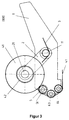
- FIG 3 shows an alternative embodiment of the device (100).
- This device (100) also points to the unrolling of a roll (4), in particular one-sided self-adhesive material (41) a handle (1) and a holder (2), which is rotatably mounted by means of the pin (11).
- Dispensing device (6) It is located below the guide roller (5), i.e. opposite the roller (4) Dispensing device (6), not as a sliding block (6), but as a combination of one Dispensing roller (63) and a pressure roller (64) is executed.
- the adhesive tape (41) When dispensing the adhesive tape (41) from the roll (4), the adhesive tape (41) is over the donor roller (63) very precisely to the pressure roller (64), which the process of Application supports by the pressure roller (64) the material (41) firmly on the surface presses.
- the pressure roller (64) is also preferably provided with a rubber coating provided to prevent any damage to the material (41) or the To prevent underground.
- Suitable materials for the components are plastics, but also a metal version is possible.
Landscapes
- Adhesive Tape Dispensing Devices (AREA)
- Adhesive Tapes (AREA)
Applications Claiming Priority (2)
| Application Number | Priority Date | Filing Date | Title |
|---|---|---|---|
| DE29914317U | 1999-08-14 | ||
| DE29914317U DE29914317U1 (de) | 1999-08-14 | 1999-08-14 | Vorrichtung zum Abrollen von auf einer Rolle befindlichem, einseitig selbstklebend ausgerüstetem Material |
Publications (1)
| Publication Number | Publication Date |
|---|---|
| EP1077193A1 true EP1077193A1 (fr) | 2001-02-21 |
Family
ID=8077580
Family Applications (1)
| Application Number | Title | Priority Date | Filing Date |
|---|---|---|---|
| EP00115956A Withdrawn EP1077193A1 (fr) | 1999-08-14 | 2000-07-26 | Dispositif pour la distribution d'un rouleau de matériau autocollant simple face |
Country Status (3)
| Country | Link |
|---|---|
| EP (1) | EP1077193A1 (fr) |
| JP (1) | JP2001072316A (fr) |
| DE (1) | DE29914317U1 (fr) |
Cited By (1)
| Publication number | Priority date | Publication date | Assignee | Title |
|---|---|---|---|---|
| EP1312569A3 (fr) * | 2001-10-19 | 2004-08-04 | J.J. Charriere | Dispositif comprenant un dévidoir applicateur et un ruban en bobine |
Families Citing this family (1)
| Publication number | Priority date | Publication date | Assignee | Title |
|---|---|---|---|---|
| DE102005034007A1 (de) * | 2005-07-18 | 2006-05-18 | Tesa Ag | Handgerät zum Abrollen von einem Klebeband aus einem insbesondere einseitig klebend ausgerüsteten Träger, dessen Klebemasse mit einem Trennmaterial eingedeckt ist |
Citations (4)
| Publication number | Priority date | Publication date | Assignee | Title |
|---|---|---|---|---|
| US2788944A (en) * | 1953-01-07 | 1957-04-16 | Better Packages Inc | Dispenser for pressure sensitive tape |
| US4818329A (en) * | 1988-03-09 | 1989-04-04 | Kranz Incorporated | Apparatus for dispensing and applying tape |
| DE9010368U1 (de) * | 1990-07-09 | 1990-09-13 | Promotion-Factory Werbeartikel-Fabrikation GmbH, 4830 Gütersloh | Spender für Markierungsband |
| EP0459654A1 (fr) * | 1990-05-14 | 1991-12-04 | Minnesota Mining And Manufacturing Company | Applicateur automatique portatif de ruban adhésif |
Family Cites Families (2)
| Publication number | Priority date | Publication date | Assignee | Title |
|---|---|---|---|---|
| DE1951339U (de) | 1966-07-08 | 1966-12-08 | Wolf & Co Stahlbau G M B H | Rebendurchzugsvorrichtung fuer hopfenpflueckmaschinen. |
| DE29723189U1 (de) | 1997-05-30 | 1998-04-30 | Beiersdorf Ag, 20253 Hamburg | Kernträgerloser Abroller |
-
1999
- 1999-08-14 DE DE29914317U patent/DE29914317U1/de not_active Expired - Lifetime
-
2000
- 2000-07-26 EP EP00115956A patent/EP1077193A1/fr not_active Withdrawn
- 2000-08-07 JP JP2000238232A patent/JP2001072316A/ja active Pending
Patent Citations (4)
| Publication number | Priority date | Publication date | Assignee | Title |
|---|---|---|---|---|
| US2788944A (en) * | 1953-01-07 | 1957-04-16 | Better Packages Inc | Dispenser for pressure sensitive tape |
| US4818329A (en) * | 1988-03-09 | 1989-04-04 | Kranz Incorporated | Apparatus for dispensing and applying tape |
| EP0459654A1 (fr) * | 1990-05-14 | 1991-12-04 | Minnesota Mining And Manufacturing Company | Applicateur automatique portatif de ruban adhésif |
| DE9010368U1 (de) * | 1990-07-09 | 1990-09-13 | Promotion-Factory Werbeartikel-Fabrikation GmbH, 4830 Gütersloh | Spender für Markierungsband |
Cited By (1)
| Publication number | Priority date | Publication date | Assignee | Title |
|---|---|---|---|---|
| EP1312569A3 (fr) * | 2001-10-19 | 2004-08-04 | J.J. Charriere | Dispositif comprenant un dévidoir applicateur et un ruban en bobine |
Also Published As
| Publication number | Publication date |
|---|---|
| JP2001072316A (ja) | 2001-03-21 |
| DE29914317U1 (de) | 1999-12-30 |
Similar Documents
| Publication | Publication Date | Title |
|---|---|---|
| EP0610590B1 (fr) | Dispositif pour poser un ruban adhésif sur le point de départ d'un rouleau | |
| EP0384988B1 (fr) | Dispositif de déroulage pour bobine de bande | |
| DE2811842C2 (de) | Abdeckmaschine | |
| DE3718065C1 (de) | Handgeraet zum Auftragen eines doppelseitig klebenden Bandes zusammen mit einem Abdeckstreifen | |
| EP3725717B1 (fr) | Distributeurs de bande adhésive | |
| DE112019001385T5 (de) | Befestigungsvorrichtung und Verfahren zum Befestigen eines streifenförmigen Elements an einer Reifeninnenoberfläche | |
| EP0868380B1 (fr) | Dispositif pour appliquer une bande de fixation adhesive | |
| DE2612373A1 (de) | Leiste mit metallueberzug und verfahren zu ihrer herstellung | |
| EP0305738B1 (fr) | Noyau-support pour l'enroulement d'un matériau en bande | |
| EP3558547B1 (fr) | Dévidoir de ruban adhésif comprenant un système de renvoi | |
| EP0380978A1 (fr) | Dispositif à main pour transférer un film d'une feuille porteuse sur un substrat | |
| DE19733935C2 (de) | System zum Aufbringen einer von einem Wickel abzuziehenden selbstklebenden Folie auf die Wand eines Körpers und Aufbringvorrichtung für ein solches System | |
| EP1077193A1 (fr) | Dispositif pour la distribution d'un rouleau de matériau autocollant simple face | |
| DE9318310U1 (de) | Handgerät für Klebebänder mit Schutzfolie | |
| EP1687119A1 (fr) | Outil de pon age a main | |
| EP1105331A1 (fr) | Appareil pour transferer sur un substrat une matiere appliquee sous forme d'un film sur une bande support | |
| EP0469461A1 (fr) | Distributeur de ruban adhésif | |
| DE3121204C2 (fr) | ||
| EP1220759B1 (fr) | Dispositif de montage | |
| DE29917738U1 (de) | Vorrichtung zum Abrollen von auf einer Rolle befindlichem, schmalem, zumindest einseitig selbstklebend ausgerüstetem Material | |
| DE2626129A1 (de) | Schleifscheibenspender | |
| DE29911048U1 (de) | Aufwickelvorrichtung für Spanngurte | |
| DE1881778U (de) | Tageskalender. | |
| DE1499049C (de) | Vorrichtung zum Wickeln von Papieroder Folienröllchen aus einem zur Hochspannungsisolation dienenden Material | |
| DE2118570C2 (de) | Handvorrichtung zum Aufbringen einer selbstklebenden Kunststoffolle auf eine Oberfläche einer Gardinenleiste |
Legal Events
| Date | Code | Title | Description |
|---|---|---|---|
| PUAI | Public reference made under article 153(3) epc to a published international application that has entered the european phase |
Free format text: ORIGINAL CODE: 0009012 |
|
| AK | Designated contracting states |
Kind code of ref document: A1 Designated state(s): DE ES FR GB IT |
|
| AX | Request for extension of the european patent |
Free format text: AL;LT;LV;MK;RO;SI |
|
| 17P | Request for examination filed |
Effective date: 20010807 |
|
| AKX | Designation fees paid |
Free format text: DE ES FR GB IT |
|
| RAP1 | Party data changed (applicant data changed or rights of an application transferred) |
Owner name: TESA AG |
|
| 17Q | First examination report despatched |
Effective date: 20021202 |
|
| STAA | Information on the status of an ep patent application or granted ep patent |
Free format text: STATUS: THE APPLICATION IS DEEMED TO BE WITHDRAWN |
|
| 18D | Application deemed to be withdrawn |
Effective date: 20030613 |