EP3558547B1 - Dévidoir de ruban adhésif comprenant un système de renvoi - Google Patents
Dévidoir de ruban adhésif comprenant un système de renvoi Download PDFInfo
- Publication number
- EP3558547B1 EP3558547B1 EP17825534.5A EP17825534A EP3558547B1 EP 3558547 B1 EP3558547 B1 EP 3558547B1 EP 17825534 A EP17825534 A EP 17825534A EP 3558547 B1 EP3558547 B1 EP 3558547B1
- Authority
- EP
- European Patent Office
- Prior art keywords
- adhesive tape
- edge
- deflection
- component
- roll
- Prior art date
- Legal status (The legal status is an assumption and is not a legal conclusion. Google has not performed a legal analysis and makes no representation as to the accuracy of the status listed.)
- Active
Links
Images


Classifications
-
- B—PERFORMING OPERATIONS; TRANSPORTING
- B05—SPRAYING OR ATOMISING IN GENERAL; APPLYING FLUENT MATERIALS TO SURFACES, IN GENERAL
- B05B—SPRAYING APPARATUS; ATOMISING APPARATUS; NOZZLES
- B05B12/00—Arrangements for controlling delivery; Arrangements for controlling the spray area
- B05B12/16—Arrangements for controlling delivery; Arrangements for controlling the spray area for controlling the spray area
- B05B12/20—Masking elements, i.e. elements defining uncoated areas on an object to be coated
- B05B12/24—Masking elements, i.e. elements defining uncoated areas on an object to be coated made at least partly of flexible material, e.g. sheets of paper or fabric
-
- A—HUMAN NECESSITIES
- A47—FURNITURE; DOMESTIC ARTICLES OR APPLIANCES; COFFEE MILLS; SPICE MILLS; SUCTION CLEANERS IN GENERAL
- A47J—KITCHEN EQUIPMENT; COFFEE MILLS; SPICE MILLS; APPARATUS FOR MAKING BEVERAGES
- A47J42/00—Coffee mills; Spice mills
- A47J42/02—Coffee mills; Spice mills having grinding cones
-
- A—HUMAN NECESSITIES
- A47—FURNITURE; DOMESTIC ARTICLES OR APPLIANCES; COFFEE MILLS; SPICE MILLS; SUCTION CLEANERS IN GENERAL
- A47J—KITCHEN EQUIPMENT; COFFEE MILLS; SPICE MILLS; APPARATUS FOR MAKING BEVERAGES
- A47J42/00—Coffee mills; Spice mills
- A47J42/38—Parts or details
-
- B—PERFORMING OPERATIONS; TRANSPORTING
- B65—CONVEYING; PACKING; STORING; HANDLING THIN OR FILAMENTARY MATERIAL
- B65H—HANDLING THIN OR FILAMENTARY MATERIAL, e.g. SHEETS, WEBS, CABLES
- B65H35/00—Delivering articles from cutting or line-perforating machines; Article or web delivery apparatus incorporating cutting or line-perforating devices, e.g. adhesive tape dispensers
- B65H35/0006—Article or web delivery apparatus incorporating cutting or line-perforating devices
- B65H35/002—Hand-held or table apparatus
- B65H35/0026—Hand-held or table apparatus for delivering pressure-sensitive adhesive tape
-
- B—PERFORMING OPERATIONS; TRANSPORTING
- B65—CONVEYING; PACKING; STORING; HANDLING THIN OR FILAMENTARY MATERIAL
- B65H—HANDLING THIN OR FILAMENTARY MATERIAL, e.g. SHEETS, WEBS, CABLES
- B65H35/00—Delivering articles from cutting or line-perforating machines; Article or web delivery apparatus incorporating cutting or line-perforating devices, e.g. adhesive tape dispensers
- B65H35/0006—Article or web delivery apparatus incorporating cutting or line-perforating devices
- B65H35/0073—Details
-
- B—PERFORMING OPERATIONS; TRANSPORTING
- B65—CONVEYING; PACKING; STORING; HANDLING THIN OR FILAMENTARY MATERIAL
- B65H—HANDLING THIN OR FILAMENTARY MATERIAL, e.g. SHEETS, WEBS, CABLES
- B65H2301/00—Handling processes for sheets or webs
- B65H2301/30—Orientation, displacement, position of the handled material
- B65H2301/34—Modifying, selecting, changing direction of displacement
- B65H2301/341—Modifying, selecting, changing direction of displacement without change of plane of displacement
- B65H2301/3411—Right angle arrangement, i.e. 90 degrees
-
- B—PERFORMING OPERATIONS; TRANSPORTING
- B65—CONVEYING; PACKING; STORING; HANDLING THIN OR FILAMENTARY MATERIAL
- B65H—HANDLING THIN OR FILAMENTARY MATERIAL, e.g. SHEETS, WEBS, CABLES
- B65H2511/00—Dimensions; Position; Numbers; Identification; Occurrences
- B65H2511/20—Location in space
- B65H2511/21—Angle
- B65H2511/216—Orientation, e.g. with respect to direction of movement
Definitions
- the invention relates to an adhesive tape dispenser and a method for sticking an adhesive tape onto a component surface.
- Adhesive tape dispensers are, of course, fundamentally known in the prior art.
- the manual adhesive tape dispenser disclosed there has a foldable housing with two housing half-shells storing a roll of adhesive tape when folded together.
- An axle for attaching the roll of adhesive tape is formed by two axle supports that can be plugged into one another and are arranged on the inside of one of the two half-shells of the housing.
- the problem with the hand tape dispenser is that guided sticking of a masking tape along an edge at a specific distance is only possible with difficulty.
- the adhesive tape consists of a backing which has an adhesive layer on one side and whose adhesive mass is covered by a strip of release material.
- the hand tape dispenser allows the strip of release material to be automatically detached from the adhesive layer of the carrier during the application process.
- This hand tape dispenser also has the disadvantage that on the one hand it is difficult to apply the tape in a guided manner along an edge and on the other hand a handle directed in the direction of application impedes the application in the direction of application.
- a hand tape dispenser for applying an adhesive tape in one application direction to a contaminated surface is known.
- a cleaning device for surface cleaning is provided in the direction of application in front of a pressure roller.
- This manual adhesive tape dispenser is also not suitable for applying adhesive tapes up to the edges of component surfaces, since their application is impeded by the adhesive tape roll.
- a standing dispenser is known, with which a "masking tape” can be unrolled and kinked during unrolling.
- the dispenser creases a special "masking tape” at the edge between an adhesive and a non-adhesive part of the tape using a specially shaped roller.
- the adhesive tape is cut off by means of one of the cutting devices and then applied to a surface of a component to be painted.
- the U.S. 3,743,150 A describes a stationary dispenser for masking tape and is fixed to an object, eg a table top, by means of clamps.
- the dispenser has a specially shaped blade that can be used to create wedge-shaped cutting edges.
- a stationary device for sticking a wafer with a masking tape is known.
- the stationary device guides the masking tape tangentially to the edge of a wafer by means of a positioning roller and a side roller or with a holding head.
- U.S. 4,067,510A describes a hand-held masking tape dispenser for masking carpets mounted in front of baseboards.
- the object of the present invention is to provide a method for sticking on an adhesive tape which avoids the disadvantages mentioned above.
- the adhesive tape dispenser according to the invention is a preferably hand-held adhesive tape dispenser with a holder for a roll of adhesive tape and a guide system for an adhesive tape pulled off the roll of adhesive tape and a deflection edge for the removed adhesive tape, which is arranged in the removal direction at the end of the guide system and which guides the removed adhesive tape from one removal direction deflects and which has a deflection axis which has a component pointing in the direction of removal and preferably aligned parallel to the direction of removal.
- a sticker direction of the Adhesive tape after the deflection edge is arranged transversely to the peeling direction according to the invention.
- the deflection axis has an axis component perpendicular to the peel-off direction and parallel to the plane of the adhesive tape.
- the axis component corresponds to the conventional arrangement of the axes of rotation of rollers and that of conventional deflection edges.
- the adhesive tape is thus deflected upwards and downwards.
- the deflection axle according to the invention has an axle component which is arranged parallel to the pull-off direction.
- the deflection axis is created by vector addition of the two axis components. It is arranged transversely to the peeling direction, i. H. at an angle other than a right angle.
- the pull-off direction is understood here to be the direction of the adhesive tape pulled off the roll of adhesive tape immediately in front of the deflection edge.
- the deflection edge is a three-dimensionally shaped edge which, however, has a one-dimensional deflection axis.
- the deflection axis is an imaginary line, preferably within the deflection edge, which extends along the longitudinal extent of the deflection edge and around which the adhesive tape is deflected.
- the deflection axis is preferably at a constant distance from the contact surface of the adhesive tape on the deflection edge in the longitudinal direction of the deflection edge.
- the peeled-off adhesive tape is deflected from the peeling-off direction in a plane of the roll of adhesive tape into a labeling direction transverse to the plane of the roll of adhesive tape.
- the plane of the roll of adhesive tape is understood to mean a plane that extends along the main directions of extent of the roll of adhesive tape. In this plane, the roll of adhesive tape is essentially shaped, preferably exactly circular.
- the adhesive tape dispenser according to the invention makes use of the idea of changing or further developing the usual geometry of the guide system for the peeled-off adhesive tape such that the plane of the adhesive tape roll and the sticker direction of the adhesive tape are no longer arranged parallel to one another, but transversely to one another.
- the adhesive tape roll with its sometimes not small diameter of several centimeters, possibly also more than 10 cm, is no longer arranged in the direction of the label of the applied adhesive tape and the movement in the direction of the label is impeded by the adhesive tape roll could, for example, if a component surface to be glued is delimited at the end in the direction of the label by a wall extending perpendicularly to the component surface and the roll of adhesive tape would hit this wall when the adhesive tape was stuck on.
- the roll of adhesive tape transversely to the application direction of the adhesive tape, it is possible to bring the adhesive tape dispenser closer to the delimiting wall.
- transverse is to be interpreted broadly here, i. This means that the adhesive tape is first pulled off the roll of adhesive tape in a direction that is preferably exactly in the plane of the roll of adhesive tape and preferably parallel to the plane of the roll of adhesive tape, while the tape that has been pulled off changes its direction after passing through the guide system and the deflection device such that a label direction, d. H. the longitudinal direction of the glued-on adhesive tape is arranged at an angle of between 1° and 179° or 181° to 359° transversely to the plane of the adhesive tape roll.
- the adhesive tape is favorably guided around a deflection edge in the deflection device, and the deflection edge includes a deflection axis at an angle between 90.5° and 179.5° or 180.5° and 269.5° to the plane of the adhesive tape roll and/or to the end the peeling direction of the adhesive tape.
- the angle of the deflection edge to the plane of the roll of adhesive tape is particularly preferably 135° or 225° or ⁇ 20°, particularly preferably ⁇ 10°, with any number of degrees between 115° and 155° or between 205° and 255° being preferably used here as well can.
- the deflection edge is arranged at an angle of 135° or 225° and the adhesive tape is thereby deflected by 90° to the left or right.
- a system which specifies a constant distance between a component edge and a glued-on adhesive strip while the adhesive tape is being stuck onto a component surface.
- the system has the function of guiding the adhesive tape dispenser along the edge of the component.
- the system favorably has a flat contact surface, preferably it is designed as a flat contact surface which can be pressed against the edge of the component, and the adhesive tape dispenser is pulled along the surface of the component while the contact surface is in constant contact with the edge of the component.
- the deflection edge is arranged obliquely to the contact surface, preferably the contact surface is aligned parallel to the direction of application.
- the contact surface is preferably adapted to the geometry of the component in order to enable the adhesive tape dispenser to be guided in a form-fitting manner.
- the deflection device is designed in one piece, and the contact surface is provided on a side facing the component, and a strip protruding toward the component is provided on the user side of the contact surface, one long side of which is beveled and forms the deflection edge.
- the deflection device is preferably designed as a deflection block, in which the system is integrally formed; the strip protruding from the deflection block is formed by molding the contact surface.
- the contact surface and the component side of the narrow strip can have a special contour of a gap or similar to be glued. be adjusted.
- the strip protrudes towards the component to which the adhesive tape is to be stuck.
- the strip protruding toward the component is beveled at a free corner, and this bevel can form the deflection edge.
- the integral formation of contact surface and deflection edge can be produced particularly inexpensively and is maintenance-free.
- the deflection edge favorably has a chamfer in order to enable a targeted application of adhesive tape.
- a pressing means for the glued-on adhesive tape is preferably provided on the side of the protruding strip facing away from the user.
- the pressing means can be a felt strip.
- the guide system particularly preferably has a plurality of deflection rollers and guide rollers, particularly preferably the deflection device has at least two rollers with laterally radially extended cheeks and at least two straight rollers.
- the former are essentially H-shaped in cross-section; the H-shaped rollers and the straight rollers are favorably alternated in the peeling direction.
- the adhesive tape has an adhesive side and a backing side, and the backing side is non-adhesive and the adhesive side is pressure-sensitive
- the peeled tape is fed over the rollers of the guiding system, and the peeled tape rolls over some rollers with its non-adhesive backing and over other rollers with its pressure-sensitive adhesive side.
- the rollers that are connected to the pressure-sensitive adhesive side are preferably plastic rollers or have at least one plastic coating that makes contact with the pressure-sensitive adhesive layer, while the rollers that are connected to the backing side of the adhesive tape are metal rollers, preferably steel rollers be able. At least the casing is preferably coated with metal.
- Two handles preferably extend from the deflection device, favorably from the deflection block, which are aligned in the sticker direction of the adhesive tape and can each be gripped with one of the user's hands.
- the handles can be designed to be foldable.
- the object is achieved by a method having the features of claim 12.
- the method is particularly suitable for use with one or more of the tape dispensers mentioned above.
- the adhesive tape is pulled off a roll of adhesive tape and guided through a guide system, and the pulled-off adhesive tape is deflected by means of a deflection device from a pull-off direction in a plane of the roll of adhesive tape into a labeling direction transverse to the plane of the roll of adhesive tape, and the deflected adhesive tape is stuck onto the component surface.
- the adhesive tape comes with its pressure-sensitive adhesive side glued to the component surface. Due to the deflection of the adhesive tape after it has been pulled off the roll of adhesive tape, the direction of removal and the direction of the label no longer coincide, but are arranged transversely to one another.
- the adhesive tape dispenser is advantageously held by the handle or handles with both hands of the user and guided from left to right or from right to left transversely in front of the user, while the adhesive tape roll is arranged in the longitudinal direction with the plane perpendicular to the user and rolls off.
- the adhesive tape dispenser can be brought closer to a laterally delimiting wall of the component surface that is arranged in the direction of the sticker.
- the adhesive tape dispenser is preferably guided at a constant distance from the edge of the component by means of a system arranged on the adhesive tape dispenser.
- the contact is advantageously designed as a contact surface, which can be embedded in a recess in the deflection block, for example, so that the contact surface of the adhesive tape dispenser is pressed against the edge of the component and then along one edge with the contact surface in constant contact with the edge of the component component is pulled along and adhesive tape is continuously stuck to the component surface at a constant distance from the edge of the component surface.
- Adhesive tape is preferably deflected at one of the angles mentioned above, favorably at an angle of 1° to 179° or 181° to 359°, preferably at an angle of 90° or 270° ⁇ 20°, particularly preferably ⁇ 10°.
- an adhesive side of the adhesive tape is deflected from a side of the peeled-off adhesive tape that faces the user to a side of the adhesive tape that has been stuck on that faces away from the user, i.
- This side is therefore preferably the pressure-sensitive adhesive side of the adhesive tape.
- a in 1 Schematically illustrated adhesive tape dispenser 1 shows a section of an adhesive tape roll 2 on which an adhesive tape 3 is wound.
- the adhesive tape 3 has a carrier layer and an adhesive layer.
- the carrier layer and the adhesive layer each form an outside of the adhesive tape 3.
- the adhesive layer is in 1 applied radially on the inside to the carrier layer of the adhesive tape 3 wound onto the adhesive tape roll 2 .
- the roll of adhesive tape 2 has a centrally arranged opening (not shown) which is rotatably mounted on a pin (not shown) of the adhesive tape dispenser 1 .
- the pin is arranged to be movable relative to a guide system.
- the guide system has a metal sheet 4 and a first deflection roller 5 which protrudes from the metal sheet 4 and is rotatably mounted on it.
- the pin is preferably pretensioned with a compression spring in the direction of the first deflection roller 5, so that the adhesive tape 3 wound on the adhesive tape roll 2 is independent of the number of adhesive tapes already unwound Adhesive tape layers with a decreasing radius constantly in contact with the first deflection roller 5.
- the adhesive tape 3 is fed to a deflection edge 10 via the guide system.
- the management system has in accordance with the embodiment 1 next to the plate 4, a plurality of guide and deflection rollers 7, 5, 8, 9, the axes of rotation of which are parallel to one another and all protrude from the same side of the plate 4.
- the metal sheet 4 is mounted on a mounting block 6, one side of which is formed integrally with the deflection edge 10.
- the deflection edge 10 is provided on a further application block which is not designed in one piece with the fastening block 6. Both blocks can be connected with screws.
- the first deflection roller 5 is arranged with its axis of rotation parallel to the longitudinal axis of the pin directly next to the roll of adhesive tape 2 in such a way that the outermost layer of adhesive tape is in direct contact with the first deflection roller 5 and the adhesive tape 3 pulled off the roll of adhesive tape 2 extends by about half the circumference of the first deflection roller 5 is guided around.
- the first deflection roller 5 has radially extended cheeks in order to prevent the adhesive tape 3 from slipping laterally off the first deflection roller 5 .
- a second deflection roller 9 is provided opposite the adhesive tape roll 2 next to the first deflection roller 5 .
- the adhesive tape 3 is guided between the first deflection roller 5 and the second deflection roller 9 during the peeling off and is in contact with both rollers.
- a guide roller 7 is provided after the second guide roller 9 in the pull-off direction A.
- the guide roller 7 and the first deflection roller 5 are preferably metal rollers, preferably steel rollers, while the second deflection roller 9 and the third deflection roller 8 are designed as plastic rollers.
- the material specifications relate to the bearing surfaces of the rollers over which the adhesive tape 3 runs. The choice of different materials generally takes into account the fact that the plastic rollers, i.e.
- the second deflection roller 9 and a third deflection roller 8 are in contact with the adhesive side of the adhesive tape 3 when they are pulled off, while the metal rollers, i.e. the first deflection roller 5 and the guide roller 7, is in contact with the non-tacky backing of the adhesive tape 3.
- the third deflection roller 8 is provided after the guide roller 7 in the removal direction A, which in turn has a plastic bearing surface for the sticky side of the adhesive tape 3 .
- the third deflection roller 8 preferably does not touch the side of the fastening block 6 facing the user.
- the adhesive tape 3 is guided to a deflection edge 10 between the side of the fastening block 6 facing the user and the third deflection roller 8 while touching both.
- the deflection edge 10 is arranged directly after the third deflection roller 8 at an angle of 45° to the direction of removal of the adhesive tape 3 .
- the deflection edge 10 is in particular also arranged at an angle of 45° to the plane formed by the roll of adhesive tape 2 .
- the deflection edge 10 is shaped so sharply that it can be subjected to a targeted pressing on of the area around it 2 deflected adhesive tape 3 allowed on a component surface. However, the deflection edge 10 must not be so sharp that the adhesive tape 3 could be severed with it.
- the deflection edge 10 has a sufficiently large radius and merely deflects the adhesive tape 3 . Contact with the component only occurs after the deflection.
- Two handles 11 , 12 each aligned in a longitudinal direction L, extend from the fastening block 6 .
- the two handles 11, 12 are each formed from a tube whose longitudinal axis aligned in the longitudinal direction L runs parallel to the axis of rotation of the adhesive tape roll 2 and also the longitudinal axes of the deflection and guide rollers 5, 8, 9, 7 and the longitudinal axis of the pin.
- FIG. 2 shows the arrangement in 1 .
- the adhesive tape 3 whose end section is wrapped around the deflection edge 10 .
- the adhesive side of the adhesive tape 3 is in 2 faces the viewer before deflection and faces away from the viewer after deflection, so that it can be applied to a component surface 16 .
- a contact surface 13 is integrally formed in the deflection block 6 ; the contact surface 13 is the wall of a recess made in the deflection block 6 .
- the deflection edge 10 is designed as a beveled corner of a strip protruding from the fastening block 6 .
- a chamfer 14 extending from the side of the fastening block 6 facing the user to the deflection edge 10 is formed.
- the adhesive tape 2 is applied in 2 in the longitudinal direction L, so that the adhesive tape dispenser 1 is held with both hands on the two handles 11, 12 and is moved along a sticker direction B, which preferably corresponds to the longitudinal direction L here.
- the adhesive tape 3 is glued, for example as a masking tape, to the component surface 16, such as the body of an automobile or add-on parts (such as parts made of metal (body/tailgate/door) or plastic (bumper)) of the same.
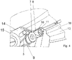
- FIG. 3 shows the adhesive tape dispenser 1 in a side view in function; the user of the adhesive tape dispenser 1 is not shown. During use, however, the two handles 11, 12 are gripped by the user and the contact surface 13 of the adhesive tape dispenser 1 is pressed against a component edge 15 of the component surface 16, so that the adhesive tape dispenser 1 can be guided and the adhesive tape 3 at a constant distance from the component edge 15 of the component surface 16 is glued to the component surface 16 along the longitudinal direction L.
- 4 shows an enlarged view of the 3 with an adhesive tape 3 already stuck to the component surface 16.
- the adhesive tape dispenser 1 can be used as shown or in any other orientation, preferably as shown or rotated by 180°.
- FIG 5 shows a opposite of the adhesive tape dispenser 1 in Figures 1-4 mirror-inverted tape dispenser 1, the same reference numerals mean the same components as in the tape dispenser, even if they are formed or mounted mirrored.
- the mirrored tape dispenser 1 is distinguished from the tape dispenser 1 in that the deflection rollers 5, 8, 9, the tape roll 2 and the guide roller 7 are not on one side of the sheet 4 as in the tape dispenser 1 of Figures 1 - 4 are arranged, but protrude on the opposite other side of the sheet 4, with the mirrored positions are maintained.
- the deflection edge 10 is also mirrored, with the mirror plane being formed by the plane of the metal sheet 4, strictly speaking by a central plane of a main propagation surface of the metal sheet 4.
- the adhesive tape 3 is thus applied in an opposite label direction -B in the case of the mirrored adhesive tape roll 1 in figure 5 to the left and in the direction of the sticker B at the adhesive tape dispenser 1 of the 1 to the right, as seen from the user who is looking at the component to be processed.
- FIG. 6 shows the detailed view of the figure 5 in a perspective top view, the detailed view includes the deflection edge 10 and the third deflection roller 8.
- the deflection edge (10) has a guide groove along which the deflected adhesive tape 3 is guided.
- the mirrored adhesive tape dispenser 1 is shown in a front view, ie starting from the component to be processed, the rollers go from the other side of the metal sheet 4 .
- the plate 4 is placed with its protruding roles on the mounting block 6 and screwed to the side or otherwise attached.
- the fastening block 6 has the deflection edge 10 with a chamfer on the end facing the component to be machined.
- the two handles 11, 12 are arranged at an angle ⁇ to each other, the handle arrangement can vary, 8 shows the handle arrangement in a view of a cross section along the line VIII - VIII in 7 .
- the adhesive tape dispenser 1 becomes the figure 5 , 6 shown in a schematic plan view, starting from the cross-sectional area VIII-VIII.
- the adhesive tape dispenser 1 is shown with a handle 11 and another handle 12 .
- other embodiments of the adhesive tape dispenser 1 and also of the mirrored adhesive tape dispenser 1 are also conceivable.
- These are in the Figures 9 and 10 shown where in the 9 a tape dispenser 1 with only one handle 11 and in the 10 an adhesive tape dispenser 1 with only the other handle 12 is shown.
- the tape dispensers 1 are Figures 8, 9 and 10 but with the tape dispenser figure 5 , 6 identical.
- a corresponding arrangement of the handles 11, 12 is of course also possible for the non-mirrored adhesive tape dispenser 1.
Landscapes
- Engineering & Computer Science (AREA)
- Mechanical Engineering (AREA)
- Food Science & Technology (AREA)
- Adhesive Tape Dispensing Devices (AREA)
- Folding Of Thin Sheet-Like Materials, Special Discharging Devices, And Others (AREA)
Claims (12)
- Dévidoir de ruban adhésif comprenantun logement pour un rouleau de ruban adhésif (2) etun système de guidage pour un ruban adhésif (3) soutiré du rouleau de ruban adhésif (2),un bord de déviation (10) pour le ruban adhésif (3) soutiré, agencé dans la direction de soutirage (A) à l'extrémité du système de guidage, qui dévie le ruban adhésif (3) soutiré de la direction de soutirage (A),le bord de déviation (10) présentant un axe de déviation, qui présente une composante orientée dans la direction de soutirage (A) et une direction de collage (B) étant agencée transversalement à la direction de soutirage (A), caractérisé en ce qu'un appui est prévu à côté d'un dispositif de déviation comprenant le bord de déviation (10), avec lequel le dispositif de déviation définit, pendant le collage sur une surface de composant (16), une distance constante entre un bord de composant (15) et le ruban adhésif (3) collé, et le bord de déviation (10) présente une rainure de guidage le long de laquelle le ruban adhésif (3) dévié est guidé.
- Dévidoir de ruban adhésif selon la revendication 1, caractérisé en ce qu'un plan du rouleau de ruban adhésif (2) est agencé transversalement à la direction de collage.
- Dévidoir de ruban adhésif selon la revendication 1 ou 2, caractérisé en ce que la direction de collage est agencée selon un angle compris entre 1° et 179° ou entre 181° et 359° par rapport à la direction de soutirage (A) du ruban adhésif (3) dans un plan de ruban adhésif.
- Dévidoir de ruban adhésif selon la revendication 3, caractérisé en ce que l'axe de déviation est agencé selon un angle compris entre 90,5° et 179,5° ou entre 180,5° et 269,5° par rapport à une direction longitudinale (L) du ruban adhésif (3).
- Dévidoir de ruban adhésif selon la revendication 4, caractérisé en ce que l'axe de déviation est agencé selon un angle de 135° ou 225° ± 20°, de préférence ± 10°.
- Dévidoir de ruban adhésif selon l'une quelconque des revendications précédentes, caractérisé en ce que l'appui présente une surface d'appui plane (13) et le bord de déviation (10) est agencé en biais par rapport à la surface d'appui (13).
- Dévidoir de ruban adhésif selon la revendication 6, caractérisé en ce que le dispositif de déviation est configuré d'un seul tenant et présente la surface d'appui (13) sur un côté tourné vers un composant central (19) et, du côté de l'utilisateur de la surface d'appui (13), une bande en saillie vers le composant central est prévue, dont un côté longitudinal est incliné vers le côté tourné vers le composant central (19) et forme le bord de déviation (10).
- Dévidoir de ruban adhésif selon la revendication 7, caractérisé en ce qu'un moyen de pression est agencé sur un côté détourné de l'utilisateur de la bande en saillie.
- Dévidoir de ruban adhésif selon l'une quelconque des revendications précédentes, caractérisé en ce que le système de guidage présente au moins un rouleau (7) comprenant deux rebords de guidage latéraux et au moins un, de préférence deux rouleaux droits (5, 8, 9).
- Procédé pour coller un ruban adhésif (3) sur une surface de composant (16), par le fait quele ruban adhésif (3) est soutiré d'un rouleau de ruban adhésif (2) etguidé à travers un système de guidage etle ruban adhésif (3) soutiré est dévié de la direction de soutirage (A) dans une direction de collage (B) agencée transversalement à la direction de soutirage (A) au moyen d'un bord de déviation (10), qui présente un axe de déviation qui présente une composante d'axe orientée dans une direction de soutirage (A), caractérisé en ce queun dévidoir de ruban adhésif (1) est guidé au moyen d'un appui agencé sur le dévidoir de ruban adhésif (1) sur un bord de composant (15) à une distance constante du bord de composant (15), et le bord de déviation (10) présente une rainure de guidage le long de laquelle le ruban adhésif (3) dévié est guidé.
- Procédé selon la revendication 10, caractérisé en ce que le ruban adhésif (3) soutiré est dévié selon un angle de 1° à 179° ou compris entre 181° et 359° dans la direction de collage (B).
- Procédé selon la revendication 11, caractérisé en ce que le ruban adhésif (3) soutiré est dévié selon un angle de 90° ou 270° ± 20°, de préférence ± 10°.
Applications Claiming Priority (2)
| Application Number | Priority Date | Filing Date | Title |
|---|---|---|---|
| DE102016226058.8A DE102016226058B4 (de) | 2016-12-22 | 2016-12-22 | Klebebandabroller mit Umlenkeinrichtung |
| PCT/EP2017/084247 WO2018115371A1 (fr) | 2016-12-22 | 2017-12-21 | Dévidoir de ruban adhésif comprenant un système de renvoi |
Publications (2)
| Publication Number | Publication Date |
|---|---|
| EP3558547A1 EP3558547A1 (fr) | 2019-10-30 |
| EP3558547B1 true EP3558547B1 (fr) | 2022-03-30 |
Family
ID=60935855
Family Applications (1)
| Application Number | Title | Priority Date | Filing Date |
|---|---|---|---|
| EP17825534.5A Active EP3558547B1 (fr) | 2016-12-22 | 2017-12-21 | Dévidoir de ruban adhésif comprenant un système de renvoi |
Country Status (7)
| Country | Link |
|---|---|
| US (1) | US11667490B2 (fr) |
| EP (1) | EP3558547B1 (fr) |
| JP (1) | JP2020502012A (fr) |
| CN (1) | CN110430945A (fr) |
| DE (2) | DE102016226058B4 (fr) |
| ES (1) | ES1222519Y (fr) |
| WO (1) | WO2018115371A1 (fr) |
Families Citing this family (4)
| Publication number | Priority date | Publication date | Assignee | Title |
|---|---|---|---|---|
| DE102018208845A1 (de) * | 2018-06-05 | 2019-12-05 | Tesa Se | Klebebandapplikator mit schwenkbarer Umlenkkanteneinheit |
| CN111807134B (zh) * | 2020-07-23 | 2021-11-16 | 法如自动化(苏州)有限公司 | 一种带拆换轮的胶带贴合工具 |
| DE102021206171B4 (de) | 2021-06-16 | 2025-05-22 | Tesa Se | Applikationsvorrichtung mit einer Helixzuführung, Robotervorrichtung und Fertigungssystem |
| DE102023126294B3 (de) * | 2023-09-27 | 2025-02-13 | Tesa Se | Applikationsvorrichtung für die Herstellung und Applikation von mehrkomponentigen bahnförmigen Klebeelementen |
Citations (1)
| Publication number | Priority date | Publication date | Assignee | Title |
|---|---|---|---|---|
| JPH09183556A (ja) * | 1995-12-31 | 1997-07-15 | Shimomoto Kaoru | テープスイングカッター |
Family Cites Families (25)
| Publication number | Priority date | Publication date | Assignee | Title |
|---|---|---|---|---|
| US3318753A (en) * | 1964-08-06 | 1967-05-09 | Ralph W Eberhart | Tape applicator |
| US3614017A (en) * | 1969-10-15 | 1971-10-19 | Steel Heddle Mfg Co | Pirn |
| US3614014A (en) * | 1970-01-06 | 1971-10-19 | William A Nichols | Tape dispensing means |
| US3743150A (en) * | 1971-12-10 | 1973-07-03 | Sapolin Paints | Method of and apparatus for preparing windows and the like for spray painting |
| DE2510064A1 (de) | 1975-03-07 | 1976-09-16 | Ego Ewald Goldmann Kittfabrik | Geraet zum auftragen eines profilierten dichtungsbandes auf eine unterlage |
| US4067510A (en) * | 1976-10-14 | 1978-01-10 | Mcgonagle Hugh K | Tape dispenser |
| WO1980002391A1 (fr) | 1979-04-30 | 1980-11-13 | C Stephens | Appareil de peinture de finition |
| DE3260660D1 (en) | 1981-08-17 | 1984-10-11 | Ciba Geigy Ag | Device for applying adhesive tape to the edge of sheet material |
| GB2189467A (en) * | 1986-04-23 | 1987-10-28 | New Jersey Machine Inc | Label dispenser with articulated guide |
| US5051551A (en) | 1989-05-18 | 1991-09-24 | Axiom Analytical, Inc. | Immersion probe for infrared internal reflectance spectroscopy |
| JPH06211410A (ja) * | 1993-01-14 | 1994-08-02 | Lintec Corp | テープ貼付ヘッドおよびテープ自動貼付装置 |
| US5393368A (en) * | 1993-02-10 | 1995-02-28 | The Gillette Company | Correction tape dispenser |
| DE4310146C1 (de) | 1993-03-29 | 1994-06-16 | Daimler Benz Ag | Robotergeführte Vorrichtung zum örtlich gezielten Abkleben von Scheibenflanschen in Fahrzeugkarosserien mit Haftklebeband |
| JP3505665B2 (ja) * | 1995-04-20 | 2004-03-08 | 株式会社トンボ鉛筆 | 字消し具又は粘着テープ容器 |
| JPH0952652A (ja) * | 1995-08-11 | 1997-02-25 | Kenji Kurata | 粘着テープ貼付器 |
| DE19546581C2 (de) * | 1995-12-13 | 2000-01-20 | Silu Verwaltung Ag | Vorrichtung zum Aufbringen von klebendem Montageband |
| JPH1059609A (ja) * | 1996-08-23 | 1998-03-03 | Toppan Moore Co Ltd | テープディスペンサー |
| DE29705259U1 (de) | 1997-03-22 | 1998-08-06 | KUKA Schweissanlagen GmbH, 86165 Augsburg | Bandaufklebevorrichtung |
| JPH1179127A (ja) * | 1997-07-15 | 1999-03-23 | Nichiban Co Ltd | 簡易結束具 |
| JPH11292384A (ja) * | 1998-04-14 | 1999-10-26 | Houju Sangyo Kk | 粘着テープ貼付け具 |
| DE102005034007A1 (de) | 2005-07-18 | 2006-05-18 | Tesa Ag | Handgerät zum Abrollen von einem Klebeband aus einem insbesondere einseitig klebend ausgerüsteten Träger, dessen Klebemasse mit einem Trennmaterial eingedeckt ist |
| DE202007011400U1 (de) | 2007-08-14 | 2008-12-24 | Tesa Ag | Klebeband-Handabroller in Kompaktform |
| DE202012004079U1 (de) | 2012-04-25 | 2012-05-09 | Tesa Se | Klebebandhandabroller |
| US9079741B2 (en) * | 2013-08-06 | 2015-07-14 | Lamus Enterprises Inc. | Tape applicator to apply tape to a vertical side of a case |
| JP6340249B2 (ja) * | 2014-05-28 | 2018-06-06 | 株式会社荏原製作所 | テープ貼り付け装置およびテープ貼り付け方法 |
-
2016
- 2016-12-22 DE DE102016226058.8A patent/DE102016226058B4/de active Active
- 2016-12-22 DE DE202016008252.4U patent/DE202016008252U1/de not_active Expired - Lifetime
-
2017
- 2017-12-21 US US16/471,434 patent/US11667490B2/en active Active
- 2017-12-21 CN CN201780084215.8A patent/CN110430945A/zh active Pending
- 2017-12-21 ES ES201890018U patent/ES1222519Y/es active Active
- 2017-12-21 EP EP17825534.5A patent/EP3558547B1/fr active Active
- 2017-12-21 JP JP2019534253A patent/JP2020502012A/ja active Pending
- 2017-12-21 WO PCT/EP2017/084247 patent/WO2018115371A1/fr not_active Ceased
Patent Citations (1)
| Publication number | Priority date | Publication date | Assignee | Title |
|---|---|---|---|---|
| JPH09183556A (ja) * | 1995-12-31 | 1997-07-15 | Shimomoto Kaoru | テープスイングカッター |
Also Published As
| Publication number | Publication date |
|---|---|
| DE102016226058B4 (de) | 2019-01-17 |
| EP3558547A1 (fr) | 2019-10-30 |
| US20210130122A1 (en) | 2021-05-06 |
| WO2018115371A1 (fr) | 2018-06-28 |
| JP2020502012A (ja) | 2020-01-23 |
| DE202016008252U1 (de) | 2017-06-23 |
| ES1222519U (es) | 2019-01-02 |
| CN110430945A (zh) | 2019-11-08 |
| DE102016226058A1 (de) | 2018-06-28 |
| US11667490B2 (en) | 2023-06-06 |
| ES1222519Y (es) | 2019-03-22 |
Similar Documents
| Publication | Publication Date | Title |
|---|---|---|
| EP3558547B1 (fr) | Dévidoir de ruban adhésif comprenant un système de renvoi | |
| DE69415039T2 (de) | Bandspender | |
| EP3725717A1 (fr) | Distributeurs de bande adhésive | |
| DE68922370T2 (de) | Vorrichtung zum Anbringen von Hüllen auf elektrische Kabelverbindungen. | |
| DE19546581A1 (de) | Vorrichtung zum Aufbringen von klebendem Montageband | |
| DE112017001575T5 (de) | Bandabgabewerkzeug | |
| CH683839A5 (de) | Handgehaltene Abdeckvorrichtung. | |
| EP1105332B1 (fr) | Appareil pour transferer sur un substrat une matiere appliquee sous forme d'un film sur une bande support | |
| DE69314479T2 (de) | Handbetaetigte vorrichtung sowie verfahren zum einbringen eines elastomer-stranges unter einer dichtung | |
| DE102011079544A1 (de) | Abroller | |
| EP1105331B1 (fr) | Appareil pour transferer sur un substrat une matiere appliquee sous forme d'un film sur une bande support | |
| DE102020114254B4 (de) | Ablösevorrichtung zum Aufkleberablösen von Trägersubstraten sowie ein Verfahren | |
| DE10085486B4 (de) | Bandaufbringvorrichtung | |
| EP0873957B1 (fr) | Dispositif pour couper une bande de papier et attacher une bande adhésive au bord de la bande | |
| EP1167257B1 (fr) | Méthode pour enrouler une bande de matériau et dispositif de bobinage | |
| DE102021126287B3 (de) | Applikator zum Verkleben von zwei Fügeteilen mittels eines doppelseitig selbstklebenden Klebestreifens mit Anzeige ausreichender Anpresskraft | |
| EP4043377A1 (fr) | Rouleau de bande adhésive et élément rapporté pour un rouleau de bande adhésive | |
| DE102023126294B3 (de) | Applikationsvorrichtung für die Herstellung und Applikation von mehrkomponentigen bahnförmigen Klebeelementen | |
| DE10351877B4 (de) | Schneidvorrichtung zum Abtrennen von Etiketten, Verfahren zum Abtrennen von Etiketten und Druckvorrichtung | |
| DE102017202728A1 (de) | Spendegerät | |
| DE3006697C2 (de) | Verfahren und Vorrichtung zum Zuführen und Anlegen einseitig beschichteten Klebebandes an elektrischenSpulen | |
| WO1999037569A1 (fr) | Appareil pour transferer un film d'une bande support sur un substrat | |
| DE102010007002A1 (de) | Bandschneider | |
| DE102020126706A1 (de) | Vorrichtung zum Halten und Abrollen eines Klebebands | |
| DE4239116A1 (en) | Line drawing and deletion arrangement for all kinds of surfaces and objects - uses long guide rod which on its underside is movable along locating edge touching it and marker element |
Legal Events
| Date | Code | Title | Description |
|---|---|---|---|
| STAA | Information on the status of an ep patent application or granted ep patent |
Free format text: STATUS: UNKNOWN |
|
| STAA | Information on the status of an ep patent application or granted ep patent |
Free format text: STATUS: THE INTERNATIONAL PUBLICATION HAS BEEN MADE |
|
| PUAI | Public reference made under article 153(3) epc to a published international application that has entered the european phase |
Free format text: ORIGINAL CODE: 0009012 |
|
| STAA | Information on the status of an ep patent application or granted ep patent |
Free format text: STATUS: REQUEST FOR EXAMINATION WAS MADE |
|
| 17P | Request for examination filed |
Effective date: 20190722 |
|
| AK | Designated contracting states |
Kind code of ref document: A1 Designated state(s): AL AT BE BG CH CY CZ DE DK EE ES FI FR GB GR HR HU IE IS IT LI LT LU LV MC MK MT NL NO PL PT RO RS SE SI SK SM TR |
|
| AX | Request for extension of the european patent |
Extension state: BA ME |
|
| DAV | Request for validation of the european patent (deleted) | ||
| DAX | Request for extension of the european patent (deleted) | ||
| RIN1 | Information on inventor provided before grant (corrected) |
Inventor name: HIMMELSBACH, PETER Inventor name: ZIBULL, MICHAEL Inventor name: GERDSMANN, THOMAS |
|
| REG | Reference to a national code |
Ref country code: DE Ref legal event code: R079 Ref document number: 502017012876 Country of ref document: DE Free format text: PREVIOUS MAIN CLASS: B05B0012240000 Ipc: A47J0042020000 |
|
| GRAP | Despatch of communication of intention to grant a patent |
Free format text: ORIGINAL CODE: EPIDOSNIGR1 |
|
| STAA | Information on the status of an ep patent application or granted ep patent |
Free format text: STATUS: GRANT OF PATENT IS INTENDED |
|
| GRAJ | Information related to disapproval of communication of intention to grant by the applicant or resumption of examination proceedings by the epo deleted |
Free format text: ORIGINAL CODE: EPIDOSDIGR1 |
|
| RIC1 | Information provided on ipc code assigned before grant |
Ipc: B05B 12/24 20180101ALI20210915BHEP Ipc: B65H 35/00 20060101ALI20210915BHEP Ipc: A47J 42/38 20060101ALI20210915BHEP Ipc: A47J 42/02 20060101AFI20210915BHEP |
|
| GRAP | Despatch of communication of intention to grant a patent |
Free format text: ORIGINAL CODE: EPIDOSNIGR1 |
|
| INTG | Intention to grant announced |
Effective date: 20211013 |
|
| INTG | Intention to grant announced |
Effective date: 20211027 |
|
| GRAS | Grant fee paid |
Free format text: ORIGINAL CODE: EPIDOSNIGR3 |
|
| GRAA | (expected) grant |
Free format text: ORIGINAL CODE: 0009210 |
|
| STAA | Information on the status of an ep patent application or granted ep patent |
Free format text: STATUS: THE PATENT HAS BEEN GRANTED |
|
| AK | Designated contracting states |
Kind code of ref document: B1 Designated state(s): AL AT BE BG CH CY CZ DE DK EE ES FI FR GB GR HR HU IE IS IT LI LT LU LV MC MK MT NL NO PL PT RO RS SE SI SK SM TR |
|
| REG | Reference to a national code |
Ref country code: GB Ref legal event code: FG4D Free format text: NOT ENGLISH |
|
| REG | Reference to a national code |
Ref country code: CH Ref legal event code: EP |
|
| REG | Reference to a national code |
Ref country code: AT Ref legal event code: REF Ref document number: 1478421 Country of ref document: AT Kind code of ref document: T Effective date: 20220415 |
|
| REG | Reference to a national code |
Ref country code: DE Ref legal event code: R096 Ref document number: 502017012876 Country of ref document: DE |
|
| REG | Reference to a national code |
Ref country code: IE Ref legal event code: FG4D Free format text: LANGUAGE OF EP DOCUMENT: GERMAN |
|
| REG | Reference to a national code |
Ref country code: LT Ref legal event code: MG9D |
|
| PG25 | Lapsed in a contracting state [announced via postgrant information from national office to epo] |
Ref country code: SE Free format text: LAPSE BECAUSE OF FAILURE TO SUBMIT A TRANSLATION OF THE DESCRIPTION OR TO PAY THE FEE WITHIN THE PRESCRIBED TIME-LIMIT Effective date: 20220330 Ref country code: RS Free format text: LAPSE BECAUSE OF FAILURE TO SUBMIT A TRANSLATION OF THE DESCRIPTION OR TO PAY THE FEE WITHIN THE PRESCRIBED TIME-LIMIT Effective date: 20220330 Ref country code: NO Free format text: LAPSE BECAUSE OF FAILURE TO SUBMIT A TRANSLATION OF THE DESCRIPTION OR TO PAY THE FEE WITHIN THE PRESCRIBED TIME-LIMIT Effective date: 20220630 Ref country code: LT Free format text: LAPSE BECAUSE OF FAILURE TO SUBMIT A TRANSLATION OF THE DESCRIPTION OR TO PAY THE FEE WITHIN THE PRESCRIBED TIME-LIMIT Effective date: 20220330 Ref country code: HR Free format text: LAPSE BECAUSE OF FAILURE TO SUBMIT A TRANSLATION OF THE DESCRIPTION OR TO PAY THE FEE WITHIN THE PRESCRIBED TIME-LIMIT Effective date: 20220330 Ref country code: BG Free format text: LAPSE BECAUSE OF FAILURE TO SUBMIT A TRANSLATION OF THE DESCRIPTION OR TO PAY THE FEE WITHIN THE PRESCRIBED TIME-LIMIT Effective date: 20220630 |
|
| REG | Reference to a national code |
Ref country code: NL Ref legal event code: MP Effective date: 20220330 |
|
| PG25 | Lapsed in a contracting state [announced via postgrant information from national office to epo] |
Ref country code: LV Free format text: LAPSE BECAUSE OF FAILURE TO SUBMIT A TRANSLATION OF THE DESCRIPTION OR TO PAY THE FEE WITHIN THE PRESCRIBED TIME-LIMIT Effective date: 20220330 Ref country code: GR Free format text: LAPSE BECAUSE OF FAILURE TO SUBMIT A TRANSLATION OF THE DESCRIPTION OR TO PAY THE FEE WITHIN THE PRESCRIBED TIME-LIMIT Effective date: 20220701 Ref country code: FI Free format text: LAPSE BECAUSE OF FAILURE TO SUBMIT A TRANSLATION OF THE DESCRIPTION OR TO PAY THE FEE WITHIN THE PRESCRIBED TIME-LIMIT Effective date: 20220330 |
|
| PG25 | Lapsed in a contracting state [announced via postgrant information from national office to epo] |
Ref country code: NL Free format text: LAPSE BECAUSE OF FAILURE TO SUBMIT A TRANSLATION OF THE DESCRIPTION OR TO PAY THE FEE WITHIN THE PRESCRIBED TIME-LIMIT Effective date: 20220330 |
|
| PG25 | Lapsed in a contracting state [announced via postgrant information from national office to epo] |
Ref country code: SM Free format text: LAPSE BECAUSE OF FAILURE TO SUBMIT A TRANSLATION OF THE DESCRIPTION OR TO PAY THE FEE WITHIN THE PRESCRIBED TIME-LIMIT Effective date: 20220330 Ref country code: SK Free format text: LAPSE BECAUSE OF FAILURE TO SUBMIT A TRANSLATION OF THE DESCRIPTION OR TO PAY THE FEE WITHIN THE PRESCRIBED TIME-LIMIT Effective date: 20220330 Ref country code: RO Free format text: LAPSE BECAUSE OF FAILURE TO SUBMIT A TRANSLATION OF THE DESCRIPTION OR TO PAY THE FEE WITHIN THE PRESCRIBED TIME-LIMIT Effective date: 20220330 Ref country code: PT Free format text: LAPSE BECAUSE OF FAILURE TO SUBMIT A TRANSLATION OF THE DESCRIPTION OR TO PAY THE FEE WITHIN THE PRESCRIBED TIME-LIMIT Effective date: 20220801 Ref country code: ES Free format text: LAPSE BECAUSE OF FAILURE TO SUBMIT A TRANSLATION OF THE DESCRIPTION OR TO PAY THE FEE WITHIN THE PRESCRIBED TIME-LIMIT Effective date: 20220330 Ref country code: EE Free format text: LAPSE BECAUSE OF FAILURE TO SUBMIT A TRANSLATION OF THE DESCRIPTION OR TO PAY THE FEE WITHIN THE PRESCRIBED TIME-LIMIT Effective date: 20220330 Ref country code: CZ Free format text: LAPSE BECAUSE OF FAILURE TO SUBMIT A TRANSLATION OF THE DESCRIPTION OR TO PAY THE FEE WITHIN THE PRESCRIBED TIME-LIMIT Effective date: 20220330 |
|
| PG25 | Lapsed in a contracting state [announced via postgrant information from national office to epo] |
Ref country code: PL Free format text: LAPSE BECAUSE OF FAILURE TO SUBMIT A TRANSLATION OF THE DESCRIPTION OR TO PAY THE FEE WITHIN THE PRESCRIBED TIME-LIMIT Effective date: 20220330 Ref country code: IS Free format text: LAPSE BECAUSE OF FAILURE TO SUBMIT A TRANSLATION OF THE DESCRIPTION OR TO PAY THE FEE WITHIN THE PRESCRIBED TIME-LIMIT Effective date: 20220730 Ref country code: AL Free format text: LAPSE BECAUSE OF FAILURE TO SUBMIT A TRANSLATION OF THE DESCRIPTION OR TO PAY THE FEE WITHIN THE PRESCRIBED TIME-LIMIT Effective date: 20220330 |
|
| REG | Reference to a national code |
Ref country code: DE Ref legal event code: R097 Ref document number: 502017012876 Country of ref document: DE |
|
| PG25 | Lapsed in a contracting state [announced via postgrant information from national office to epo] |
Ref country code: DK Free format text: LAPSE BECAUSE OF FAILURE TO SUBMIT A TRANSLATION OF THE DESCRIPTION OR TO PAY THE FEE WITHIN THE PRESCRIBED TIME-LIMIT Effective date: 20220330 |
|
| PGFP | Annual fee paid to national office [announced via postgrant information from national office to epo] |
Ref country code: DE Payment date: 20221213 Year of fee payment: 6 |
|
| PLBE | No opposition filed within time limit |
Free format text: ORIGINAL CODE: 0009261 |
|
| STAA | Information on the status of an ep patent application or granted ep patent |
Free format text: STATUS: NO OPPOSITION FILED WITHIN TIME LIMIT |
|
| 26N | No opposition filed |
Effective date: 20230103 |
|
| PG25 | Lapsed in a contracting state [announced via postgrant information from national office to epo] |
Ref country code: SI Free format text: LAPSE BECAUSE OF FAILURE TO SUBMIT A TRANSLATION OF THE DESCRIPTION OR TO PAY THE FEE WITHIN THE PRESCRIBED TIME-LIMIT Effective date: 20220330 |
|
| PG25 | Lapsed in a contracting state [announced via postgrant information from national office to epo] |
Ref country code: IT Free format text: LAPSE BECAUSE OF FAILURE TO SUBMIT A TRANSLATION OF THE DESCRIPTION OR TO PAY THE FEE WITHIN THE PRESCRIBED TIME-LIMIT Effective date: 20220330 |
|
| REG | Reference to a national code |
Ref country code: CH Ref legal event code: PL |
|
| REG | Reference to a national code |
Ref country code: BE Ref legal event code: MM Effective date: 20221231 |
|
| PG25 | Lapsed in a contracting state [announced via postgrant information from national office to epo] |
Ref country code: LU Free format text: LAPSE BECAUSE OF NON-PAYMENT OF DUE FEES Effective date: 20221221 |
|
| PG25 | Lapsed in a contracting state [announced via postgrant information from national office to epo] |
Ref country code: LI Free format text: LAPSE BECAUSE OF NON-PAYMENT OF DUE FEES Effective date: 20221231 Ref country code: IE Free format text: LAPSE BECAUSE OF NON-PAYMENT OF DUE FEES Effective date: 20221221 Ref country code: CH Free format text: LAPSE BECAUSE OF NON-PAYMENT OF DUE FEES Effective date: 20221231 |
|
| PG25 | Lapsed in a contracting state [announced via postgrant information from national office to epo] |
Ref country code: BE Free format text: LAPSE BECAUSE OF NON-PAYMENT OF DUE FEES Effective date: 20221231 |
|
| REG | Reference to a national code |
Ref country code: AT Ref legal event code: MM01 Ref document number: 1478421 Country of ref document: AT Kind code of ref document: T Effective date: 20221221 |
|
| PG25 | Lapsed in a contracting state [announced via postgrant information from national office to epo] |
Ref country code: HU Free format text: LAPSE BECAUSE OF FAILURE TO SUBMIT A TRANSLATION OF THE DESCRIPTION OR TO PAY THE FEE WITHIN THE PRESCRIBED TIME-LIMIT; INVALID AB INITIO Effective date: 20171221 |
|
| PG25 | Lapsed in a contracting state [announced via postgrant information from national office to epo] |
Ref country code: AT Free format text: LAPSE BECAUSE OF NON-PAYMENT OF DUE FEES Effective date: 20221221 |
|
| PG25 | Lapsed in a contracting state [announced via postgrant information from national office to epo] |
Ref country code: CY Free format text: LAPSE BECAUSE OF FAILURE TO SUBMIT A TRANSLATION OF THE DESCRIPTION OR TO PAY THE FEE WITHIN THE PRESCRIBED TIME-LIMIT Effective date: 20220330 Ref country code: AT Free format text: LAPSE BECAUSE OF NON-PAYMENT OF DUE FEES Effective date: 20221221 |
|
| PG25 | Lapsed in a contracting state [announced via postgrant information from national office to epo] |
Ref country code: MK Free format text: LAPSE BECAUSE OF FAILURE TO SUBMIT A TRANSLATION OF THE DESCRIPTION OR TO PAY THE FEE WITHIN THE PRESCRIBED TIME-LIMIT Effective date: 20220330 |
|
| PG25 | Lapsed in a contracting state [announced via postgrant information from national office to epo] |
Ref country code: MC Free format text: LAPSE BECAUSE OF FAILURE TO SUBMIT A TRANSLATION OF THE DESCRIPTION OR TO PAY THE FEE WITHIN THE PRESCRIBED TIME-LIMIT Effective date: 20220330 |
|
| PG25 | Lapsed in a contracting state [announced via postgrant information from national office to epo] |
Ref country code: MC Free format text: LAPSE BECAUSE OF FAILURE TO SUBMIT A TRANSLATION OF THE DESCRIPTION OR TO PAY THE FEE WITHIN THE PRESCRIBED TIME-LIMIT Effective date: 20220330 |
|
| REG | Reference to a national code |
Ref country code: DE Ref legal event code: R119 Ref document number: 502017012876 Country of ref document: DE |
|
| PG25 | Lapsed in a contracting state [announced via postgrant information from national office to epo] |
Ref country code: MT Free format text: LAPSE BECAUSE OF FAILURE TO SUBMIT A TRANSLATION OF THE DESCRIPTION OR TO PAY THE FEE WITHIN THE PRESCRIBED TIME-LIMIT Effective date: 20220330 |
|
| PG25 | Lapsed in a contracting state [announced via postgrant information from national office to epo] |
Ref country code: DE Free format text: LAPSE BECAUSE OF NON-PAYMENT OF DUE FEES Effective date: 20240702 |
|
| PG25 | Lapsed in a contracting state [announced via postgrant information from national office to epo] |
Ref country code: DE Free format text: LAPSE BECAUSE OF NON-PAYMENT OF DUE FEES Effective date: 20240702 |
|
| PG25 | Lapsed in a contracting state [announced via postgrant information from national office to epo] |
Ref country code: TR Free format text: LAPSE BECAUSE OF FAILURE TO SUBMIT A TRANSLATION OF THE DESCRIPTION OR TO PAY THE FEE WITHIN THE PRESCRIBED TIME-LIMIT Effective date: 20220330 |
|
| PGFP | Annual fee paid to national office [announced via postgrant information from national office to epo] |
Ref country code: GB Payment date: 20251219 Year of fee payment: 9 |
|
| PGFP | Annual fee paid to national office [announced via postgrant information from national office to epo] |
Ref country code: FR Payment date: 20251229 Year of fee payment: 9 |