EP1078212B1 - Installation de distillation d'air et boite froide correspondante - Google Patents
Installation de distillation d'air et boite froide correspondante Download PDFInfo
- Publication number
- EP1078212B1 EP1078212B1 EP99915849A EP99915849A EP1078212B1 EP 1078212 B1 EP1078212 B1 EP 1078212B1 EP 99915849 A EP99915849 A EP 99915849A EP 99915849 A EP99915849 A EP 99915849A EP 1078212 B1 EP1078212 B1 EP 1078212B1
- Authority
- EP
- European Patent Office
- Prior art keywords
- column
- pressure column
- low
- pressure
- medium
- Prior art date
- Legal status (The legal status is an assumption and is not a legal conclusion. Google has not performed a legal analysis and makes no representation as to the accuracy of the status listed.)
- Expired - Lifetime
Links
- 238000004821 distillation Methods 0.000 title claims abstract description 19
- 238000002156 mixing Methods 0.000 claims abstract description 27
- 239000012530 fluid Substances 0.000 claims abstract description 21
- XKRFYHLGVUSROY-UHFFFAOYSA-N Argon Chemical compound [Ar] XKRFYHLGVUSROY-UHFFFAOYSA-N 0.000 claims abstract description 10
- 229910052786 argon Inorganic materials 0.000 claims abstract description 5
- 239000007788 liquid Substances 0.000 claims description 23
- QVGXLLKOCUKJST-UHFFFAOYSA-N atomic oxygen Chemical compound [O] QVGXLLKOCUKJST-UHFFFAOYSA-N 0.000 claims description 16
- 239000001301 oxygen Substances 0.000 claims description 16
- 229910052760 oxygen Inorganic materials 0.000 claims description 16
- MYMOFIZGZYHOMD-UHFFFAOYSA-N Dioxygen Chemical compound O=O MYMOFIZGZYHOMD-UHFFFAOYSA-N 0.000 claims description 12
- 238000010276 construction Methods 0.000 claims description 10
- 239000007789 gas Substances 0.000 claims description 10
- 238000009413 insulation Methods 0.000 claims description 4
- 238000000034 method Methods 0.000 claims description 3
- 238000000926 separation method Methods 0.000 claims description 3
- 238000009434 installation Methods 0.000 description 19
- IJGRMHOSHXDMSA-UHFFFAOYSA-N Atomic nitrogen Chemical compound N#N IJGRMHOSHXDMSA-UHFFFAOYSA-N 0.000 description 18
- 239000000203 mixture Substances 0.000 description 9
- 229910052757 nitrogen Inorganic materials 0.000 description 9
- 238000004519 manufacturing process Methods 0.000 description 4
- 238000009417 prefabrication Methods 0.000 description 4
- 235000019362 perlite Nutrition 0.000 description 3
- 239000010451 perlite Substances 0.000 description 3
- 238000001816 cooling Methods 0.000 description 2
- 230000001419 dependent effect Effects 0.000 description 2
- 229910001882 dioxygen Inorganic materials 0.000 description 2
- 238000001179 sorption measurement Methods 0.000 description 2
- 229910000831 Steel Inorganic materials 0.000 description 1
- 238000004887 air purification Methods 0.000 description 1
- 230000001934 delay Effects 0.000 description 1
- 230000000694 effects Effects 0.000 description 1
- 238000005265 energy consumption Methods 0.000 description 1
- 230000005484 gravity Effects 0.000 description 1
- 238000002955 isolation Methods 0.000 description 1
- 238000005086 pumping Methods 0.000 description 1
- 239000010959 steel Substances 0.000 description 1
Images

Classifications
-
- F—MECHANICAL ENGINEERING; LIGHTING; HEATING; WEAPONS; BLASTING
- F25—REFRIGERATION OR COOLING; COMBINED HEATING AND REFRIGERATION SYSTEMS; HEAT PUMP SYSTEMS; MANUFACTURE OR STORAGE OF ICE; LIQUEFACTION SOLIDIFICATION OF GASES
- F25J—LIQUEFACTION, SOLIDIFICATION OR SEPARATION OF GASES OR GASEOUS OR LIQUEFIED GASEOUS MIXTURES BY PRESSURE AND COLD TREATMENT OR BY BRINGING THEM INTO THE SUPERCRITICAL STATE
- F25J3/00—Processes or apparatus for separating the constituents of gaseous or liquefied gaseous mixtures involving the use of liquefaction or solidification
- F25J3/02—Processes or apparatus for separating the constituents of gaseous or liquefied gaseous mixtures involving the use of liquefaction or solidification by rectification, i.e. by continuous interchange of heat and material between a vapour stream and a liquid stream
- F25J3/04—Processes or apparatus for separating the constituents of gaseous or liquefied gaseous mixtures involving the use of liquefaction or solidification by rectification, i.e. by continuous interchange of heat and material between a vapour stream and a liquid stream for air
- F25J3/04763—Start-up or control of the process; Details of the apparatus used
- F25J3/04866—Construction and layout of air fractionation equipments, e.g. valves, machines
- F25J3/0489—Modularity and arrangement of parts of the air fractionation unit, in particular of the cold box, e.g. pre-fabrication, assembling and erection, dimensions, horizontal layout "plot"
-
- F—MECHANICAL ENGINEERING; LIGHTING; HEATING; WEAPONS; BLASTING
- F25—REFRIGERATION OR COOLING; COMBINED HEATING AND REFRIGERATION SYSTEMS; HEAT PUMP SYSTEMS; MANUFACTURE OR STORAGE OF ICE; LIQUEFACTION SOLIDIFICATION OF GASES
- F25J—LIQUEFACTION, SOLIDIFICATION OR SEPARATION OF GASES OR GASEOUS OR LIQUEFIED GASEOUS MIXTURES BY PRESSURE AND COLD TREATMENT OR BY BRINGING THEM INTO THE SUPERCRITICAL STATE
- F25J3/00—Processes or apparatus for separating the constituents of gaseous or liquefied gaseous mixtures involving the use of liquefaction or solidification
- F25J3/02—Processes or apparatus for separating the constituents of gaseous or liquefied gaseous mixtures involving the use of liquefaction or solidification by rectification, i.e. by continuous interchange of heat and material between a vapour stream and a liquid stream
- F25J3/04—Processes or apparatus for separating the constituents of gaseous or liquefied gaseous mixtures involving the use of liquefaction or solidification by rectification, i.e. by continuous interchange of heat and material between a vapour stream and a liquid stream for air
- F25J3/04248—Generation of cold for compensating heat leaks or liquid production, e.g. by Joule-Thompson expansion
- F25J3/04284—Generation of cold for compensating heat leaks or liquid production, e.g. by Joule-Thompson expansion using internal refrigeration by open-loop gas work expansion, e.g. of intermediate or oxygen enriched (waste-)streams
- F25J3/0429—Generation of cold for compensating heat leaks or liquid production, e.g. by Joule-Thompson expansion using internal refrigeration by open-loop gas work expansion, e.g. of intermediate or oxygen enriched (waste-)streams of feed air, e.g. used as waste or product air or expanded into an auxiliary column
- F25J3/04303—Lachmann expansion, i.e. expanded into oxygen producing or low pressure column
-
- F—MECHANICAL ENGINEERING; LIGHTING; HEATING; WEAPONS; BLASTING
- F25—REFRIGERATION OR COOLING; COMBINED HEATING AND REFRIGERATION SYSTEMS; HEAT PUMP SYSTEMS; MANUFACTURE OR STORAGE OF ICE; LIQUEFACTION SOLIDIFICATION OF GASES
- F25J—LIQUEFACTION, SOLIDIFICATION OR SEPARATION OF GASES OR GASEOUS OR LIQUEFIED GASEOUS MIXTURES BY PRESSURE AND COLD TREATMENT OR BY BRINGING THEM INTO THE SUPERCRITICAL STATE
- F25J3/00—Processes or apparatus for separating the constituents of gaseous or liquefied gaseous mixtures involving the use of liquefaction or solidification
- F25J3/02—Processes or apparatus for separating the constituents of gaseous or liquefied gaseous mixtures involving the use of liquefaction or solidification by rectification, i.e. by continuous interchange of heat and material between a vapour stream and a liquid stream
- F25J3/04—Processes or apparatus for separating the constituents of gaseous or liquefied gaseous mixtures involving the use of liquefaction or solidification by rectification, i.e. by continuous interchange of heat and material between a vapour stream and a liquid stream for air
- F25J3/04406—Processes or apparatus for separating the constituents of gaseous or liquefied gaseous mixtures involving the use of liquefaction or solidification by rectification, i.e. by continuous interchange of heat and material between a vapour stream and a liquid stream for air using a dual pressure main column system
- F25J3/04412—Processes or apparatus for separating the constituents of gaseous or liquefied gaseous mixtures involving the use of liquefaction or solidification by rectification, i.e. by continuous interchange of heat and material between a vapour stream and a liquid stream for air using a dual pressure main column system in a classical double column flowsheet, i.e. with thermal coupling by a main reboiler-condenser in the bottom of low pressure respectively top of high pressure column
-
- F—MECHANICAL ENGINEERING; LIGHTING; HEATING; WEAPONS; BLASTING
- F25—REFRIGERATION OR COOLING; COMBINED HEATING AND REFRIGERATION SYSTEMS; HEAT PUMP SYSTEMS; MANUFACTURE OR STORAGE OF ICE; LIQUEFACTION SOLIDIFICATION OF GASES
- F25J—LIQUEFACTION, SOLIDIFICATION OR SEPARATION OF GASES OR GASEOUS OR LIQUEFIED GASEOUS MIXTURES BY PRESSURE AND COLD TREATMENT OR BY BRINGING THEM INTO THE SUPERCRITICAL STATE
- F25J3/00—Processes or apparatus for separating the constituents of gaseous or liquefied gaseous mixtures involving the use of liquefaction or solidification
- F25J3/02—Processes or apparatus for separating the constituents of gaseous or liquefied gaseous mixtures involving the use of liquefaction or solidification by rectification, i.e. by continuous interchange of heat and material between a vapour stream and a liquid stream
- F25J3/04—Processes or apparatus for separating the constituents of gaseous or liquefied gaseous mixtures involving the use of liquefaction or solidification by rectification, i.e. by continuous interchange of heat and material between a vapour stream and a liquid stream for air
- F25J3/04406—Processes or apparatus for separating the constituents of gaseous or liquefied gaseous mixtures involving the use of liquefaction or solidification by rectification, i.e. by continuous interchange of heat and material between a vapour stream and a liquid stream for air using a dual pressure main column system
- F25J3/04418—Processes or apparatus for separating the constituents of gaseous or liquefied gaseous mixtures involving the use of liquefaction or solidification by rectification, i.e. by continuous interchange of heat and material between a vapour stream and a liquid stream for air using a dual pressure main column system with thermally overlapping high and low pressure columns
-
- F—MECHANICAL ENGINEERING; LIGHTING; HEATING; WEAPONS; BLASTING
- F25—REFRIGERATION OR COOLING; COMBINED HEATING AND REFRIGERATION SYSTEMS; HEAT PUMP SYSTEMS; MANUFACTURE OR STORAGE OF ICE; LIQUEFACTION SOLIDIFICATION OF GASES
- F25J—LIQUEFACTION, SOLIDIFICATION OR SEPARATION OF GASES OR GASEOUS OR LIQUEFIED GASEOUS MIXTURES BY PRESSURE AND COLD TREATMENT OR BY BRINGING THEM INTO THE SUPERCRITICAL STATE
- F25J3/00—Processes or apparatus for separating the constituents of gaseous or liquefied gaseous mixtures involving the use of liquefaction or solidification
- F25J3/02—Processes or apparatus for separating the constituents of gaseous or liquefied gaseous mixtures involving the use of liquefaction or solidification by rectification, i.e. by continuous interchange of heat and material between a vapour stream and a liquid stream
- F25J3/04—Processes or apparatus for separating the constituents of gaseous or liquefied gaseous mixtures involving the use of liquefaction or solidification by rectification, i.e. by continuous interchange of heat and material between a vapour stream and a liquid stream for air
- F25J3/04436—Processes or apparatus for separating the constituents of gaseous or liquefied gaseous mixtures involving the use of liquefaction or solidification by rectification, i.e. by continuous interchange of heat and material between a vapour stream and a liquid stream for air using at least a triple pressure main column system
- F25J3/04448—Processes or apparatus for separating the constituents of gaseous or liquefied gaseous mixtures involving the use of liquefaction or solidification by rectification, i.e. by continuous interchange of heat and material between a vapour stream and a liquid stream for air using at least a triple pressure main column system in a double column flowsheet with an intermediate pressure column
-
- F—MECHANICAL ENGINEERING; LIGHTING; HEATING; WEAPONS; BLASTING
- F25—REFRIGERATION OR COOLING; COMBINED HEATING AND REFRIGERATION SYSTEMS; HEAT PUMP SYSTEMS; MANUFACTURE OR STORAGE OF ICE; LIQUEFACTION SOLIDIFICATION OF GASES
- F25J—LIQUEFACTION, SOLIDIFICATION OR SEPARATION OF GASES OR GASEOUS OR LIQUEFIED GASEOUS MIXTURES BY PRESSURE AND COLD TREATMENT OR BY BRINGING THEM INTO THE SUPERCRITICAL STATE
- F25J3/00—Processes or apparatus for separating the constituents of gaseous or liquefied gaseous mixtures involving the use of liquefaction or solidification
- F25J3/02—Processes or apparatus for separating the constituents of gaseous or liquefied gaseous mixtures involving the use of liquefaction or solidification by rectification, i.e. by continuous interchange of heat and material between a vapour stream and a liquid stream
- F25J3/04—Processes or apparatus for separating the constituents of gaseous or liquefied gaseous mixtures involving the use of liquefaction or solidification by rectification, i.e. by continuous interchange of heat and material between a vapour stream and a liquid stream for air
- F25J3/0446—Processes or apparatus for separating the constituents of gaseous or liquefied gaseous mixtures involving the use of liquefaction or solidification by rectification, i.e. by continuous interchange of heat and material between a vapour stream and a liquid stream for air using the heat generated by mixing two different phases
- F25J3/04466—Processes or apparatus for separating the constituents of gaseous or liquefied gaseous mixtures involving the use of liquefaction or solidification by rectification, i.e. by continuous interchange of heat and material between a vapour stream and a liquid stream for air using the heat generated by mixing two different phases for producing oxygen as a mixing column overhead gas by mixing gaseous air feed and liquid oxygen
-
- F—MECHANICAL ENGINEERING; LIGHTING; HEATING; WEAPONS; BLASTING
- F25—REFRIGERATION OR COOLING; COMBINED HEATING AND REFRIGERATION SYSTEMS; HEAT PUMP SYSTEMS; MANUFACTURE OR STORAGE OF ICE; LIQUEFACTION SOLIDIFICATION OF GASES
- F25J—LIQUEFACTION, SOLIDIFICATION OR SEPARATION OF GASES OR GASEOUS OR LIQUEFIED GASEOUS MIXTURES BY PRESSURE AND COLD TREATMENT OR BY BRINGING THEM INTO THE SUPERCRITICAL STATE
- F25J3/00—Processes or apparatus for separating the constituents of gaseous or liquefied gaseous mixtures involving the use of liquefaction or solidification
- F25J3/02—Processes or apparatus for separating the constituents of gaseous or liquefied gaseous mixtures involving the use of liquefaction or solidification by rectification, i.e. by continuous interchange of heat and material between a vapour stream and a liquid stream
- F25J3/04—Processes or apparatus for separating the constituents of gaseous or liquefied gaseous mixtures involving the use of liquefaction or solidification by rectification, i.e. by continuous interchange of heat and material between a vapour stream and a liquid stream for air
- F25J3/04642—Recovering noble gases from air
- F25J3/04648—Recovering noble gases from air argon
- F25J3/04654—Producing crude argon in a crude argon column
- F25J3/04666—Producing crude argon in a crude argon column as a parallel working rectification column of the low pressure column in a dual pressure main column system
- F25J3/04672—Producing crude argon in a crude argon column as a parallel working rectification column of the low pressure column in a dual pressure main column system having a top condenser
- F25J3/04678—Producing crude argon in a crude argon column as a parallel working rectification column of the low pressure column in a dual pressure main column system having a top condenser cooled by oxygen enriched liquid from high pressure column bottoms
-
- F—MECHANICAL ENGINEERING; LIGHTING; HEATING; WEAPONS; BLASTING
- F25—REFRIGERATION OR COOLING; COMBINED HEATING AND REFRIGERATION SYSTEMS; HEAT PUMP SYSTEMS; MANUFACTURE OR STORAGE OF ICE; LIQUEFACTION SOLIDIFICATION OF GASES
- F25J—LIQUEFACTION, SOLIDIFICATION OR SEPARATION OF GASES OR GASEOUS OR LIQUEFIED GASEOUS MIXTURES BY PRESSURE AND COLD TREATMENT OR BY BRINGING THEM INTO THE SUPERCRITICAL STATE
- F25J3/00—Processes or apparatus for separating the constituents of gaseous or liquefied gaseous mixtures involving the use of liquefaction or solidification
- F25J3/02—Processes or apparatus for separating the constituents of gaseous or liquefied gaseous mixtures involving the use of liquefaction or solidification by rectification, i.e. by continuous interchange of heat and material between a vapour stream and a liquid stream
- F25J3/04—Processes or apparatus for separating the constituents of gaseous or liquefied gaseous mixtures involving the use of liquefaction or solidification by rectification, i.e. by continuous interchange of heat and material between a vapour stream and a liquid stream for air
- F25J3/04763—Start-up or control of the process; Details of the apparatus used
- F25J3/04866—Construction and layout of air fractionation equipments, e.g. valves, machines
- F25J3/04872—Vertical layout of cold equipments within in the cold box, e.g. columns, heat exchangers etc.
-
- F—MECHANICAL ENGINEERING; LIGHTING; HEATING; WEAPONS; BLASTING
- F25—REFRIGERATION OR COOLING; COMBINED HEATING AND REFRIGERATION SYSTEMS; HEAT PUMP SYSTEMS; MANUFACTURE OR STORAGE OF ICE; LIQUEFACTION SOLIDIFICATION OF GASES
- F25J—LIQUEFACTION, SOLIDIFICATION OR SEPARATION OF GASES OR GASEOUS OR LIQUEFIED GASEOUS MIXTURES BY PRESSURE AND COLD TREATMENT OR BY BRINGING THEM INTO THE SUPERCRITICAL STATE
- F25J3/00—Processes or apparatus for separating the constituents of gaseous or liquefied gaseous mixtures involving the use of liquefaction or solidification
- F25J3/02—Processes or apparatus for separating the constituents of gaseous or liquefied gaseous mixtures involving the use of liquefaction or solidification by rectification, i.e. by continuous interchange of heat and material between a vapour stream and a liquid stream
- F25J3/04—Processes or apparatus for separating the constituents of gaseous or liquefied gaseous mixtures involving the use of liquefaction or solidification by rectification, i.e. by continuous interchange of heat and material between a vapour stream and a liquid stream for air
- F25J3/04763—Start-up or control of the process; Details of the apparatus used
- F25J3/04866—Construction and layout of air fractionation equipments, e.g. valves, machines
- F25J3/04896—Details of columns, e.g. internals, inlet/outlet devices
- F25J3/04915—Combinations of different material exchange elements, e.g. within different columns
-
- F—MECHANICAL ENGINEERING; LIGHTING; HEATING; WEAPONS; BLASTING
- F25—REFRIGERATION OR COOLING; COMBINED HEATING AND REFRIGERATION SYSTEMS; HEAT PUMP SYSTEMS; MANUFACTURE OR STORAGE OF ICE; LIQUEFACTION SOLIDIFICATION OF GASES
- F25J—LIQUEFACTION, SOLIDIFICATION OR SEPARATION OF GASES OR GASEOUS OR LIQUEFIED GASEOUS MIXTURES BY PRESSURE AND COLD TREATMENT OR BY BRINGING THEM INTO THE SUPERCRITICAL STATE
- F25J2200/00—Processes or apparatus using separation by rectification
- F25J2200/04—Processes or apparatus using separation by rectification in a dual pressure main column system
- F25J2200/06—Processes or apparatus using separation by rectification in a dual pressure main column system in a classical double column flow-sheet, i.e. with thermal coupling by a main reboiler-condenser in the bottom of low pressure respectively top of high pressure column
-
- F—MECHANICAL ENGINEERING; LIGHTING; HEATING; WEAPONS; BLASTING
- F25—REFRIGERATION OR COOLING; COMBINED HEATING AND REFRIGERATION SYSTEMS; HEAT PUMP SYSTEMS; MANUFACTURE OR STORAGE OF ICE; LIQUEFACTION SOLIDIFICATION OF GASES
- F25J—LIQUEFACTION, SOLIDIFICATION OR SEPARATION OF GASES OR GASEOUS OR LIQUEFIED GASEOUS MIXTURES BY PRESSURE AND COLD TREATMENT OR BY BRINGING THEM INTO THE SUPERCRITICAL STATE
- F25J2235/00—Processes or apparatus involving steps for increasing the pressure or for conveying of liquid process streams
- F25J2235/50—Processes or apparatus involving steps for increasing the pressure or for conveying of liquid process streams the fluid being oxygen
-
- F—MECHANICAL ENGINEERING; LIGHTING; HEATING; WEAPONS; BLASTING
- F25—REFRIGERATION OR COOLING; COMBINED HEATING AND REFRIGERATION SYSTEMS; HEAT PUMP SYSTEMS; MANUFACTURE OR STORAGE OF ICE; LIQUEFACTION SOLIDIFICATION OF GASES
- F25J—LIQUEFACTION, SOLIDIFICATION OR SEPARATION OF GASES OR GASEOUS OR LIQUEFIED GASEOUS MIXTURES BY PRESSURE AND COLD TREATMENT OR BY BRINGING THEM INTO THE SUPERCRITICAL STATE
- F25J2240/00—Processes or apparatus involving steps for expanding of process streams
- F25J2240/40—Expansion without extracting work, i.e. isenthalpic throttling, e.g. JT valve, regulating valve or venturi, or isentropic nozzle, e.g. Laval
- F25J2240/42—Expansion without extracting work, i.e. isenthalpic throttling, e.g. JT valve, regulating valve or venturi, or isentropic nozzle, e.g. Laval the fluid being air
-
- F—MECHANICAL ENGINEERING; LIGHTING; HEATING; WEAPONS; BLASTING
- F25—REFRIGERATION OR COOLING; COMBINED HEATING AND REFRIGERATION SYSTEMS; HEAT PUMP SYSTEMS; MANUFACTURE OR STORAGE OF ICE; LIQUEFACTION SOLIDIFICATION OF GASES
- F25J—LIQUEFACTION, SOLIDIFICATION OR SEPARATION OF GASES OR GASEOUS OR LIQUEFIED GASEOUS MIXTURES BY PRESSURE AND COLD TREATMENT OR BY BRINGING THEM INTO THE SUPERCRITICAL STATE
- F25J2290/00—Other details not covered by groups F25J2200/00 - F25J2280/00
- F25J2290/62—Details of storing a fluid in a tank
-
- Y—GENERAL TAGGING OF NEW TECHNOLOGICAL DEVELOPMENTS; GENERAL TAGGING OF CROSS-SECTIONAL TECHNOLOGIES SPANNING OVER SEVERAL SECTIONS OF THE IPC; TECHNICAL SUBJECTS COVERED BY FORMER USPC CROSS-REFERENCE ART COLLECTIONS [XRACs] AND DIGESTS
- Y10—TECHNICAL SUBJECTS COVERED BY FORMER USPC
- Y10S—TECHNICAL SUBJECTS COVERED BY FORMER USPC CROSS-REFERENCE ART COLLECTIONS [XRACs] AND DIGESTS
- Y10S62/00—Refrigeration
- Y10S62/902—Apparatus
- Y10S62/905—Column
-
- Y—GENERAL TAGGING OF NEW TECHNOLOGICAL DEVELOPMENTS; GENERAL TAGGING OF CROSS-SECTIONAL TECHNOLOGIES SPANNING OVER SEVERAL SECTIONS OF THE IPC; TECHNICAL SUBJECTS COVERED BY FORMER USPC CROSS-REFERENCE ART COLLECTIONS [XRACs] AND DIGESTS
- Y10—TECHNICAL SUBJECTS COVERED BY FORMER USPC
- Y10S—TECHNICAL SUBJECTS COVERED BY FORMER USPC CROSS-REFERENCE ART COLLECTIONS [XRACs] AND DIGESTS
- Y10S62/00—Refrigeration
- Y10S62/902—Apparatus
- Y10S62/905—Column
- Y10S62/907—Insulation
Definitions
- the present invention relates to an installation of air distillation of the type comprising a medium column pressure, a low pressure column and a vaporizer-condenser of heat exchange relationship of a gas circulating with a liquid from the low pressure column.
- the invention applies in particular to the supply of impure oxygen, for example for food blast furnaces in the steel industry.
- Such a column mixing operates under substantially equal pressure or below average pressure. It is supplied with tank by a gas such as purified and compressed air and in head by a liquid more volatile than gas, such as impure liquid oxygen taken from the bottom column tank pressure and pumped to the pressure of the column mixed. It is drawn off at the head of such a mixing column impure oxygen gas to be supplied substantially below the mixing column pressure.
- a gas such as purified and compressed air
- a liquid more volatile than gas such as impure liquid oxygen taken from the bottom column tank pressure and pumped to the pressure of the column mixed. It is drawn off at the head of such a mixing column impure oxygen gas to be supplied substantially below the mixing column pressure.
- the low pressure column overcomes the vaporizer-condenser, which itself overcomes the column medium pressure.
- the double column then forms a single erected structure and the mixing column is arranged to side of the double column.
- This double provision column allows the prefabrication in workshop of installation in a limited number of cold boxes or packages of which one main package includes the double column. These packages are then transported to site, where they are erected and connected to form the installation of air distillation.
- vaporizers-condensers The construction of vaporizers-condensers is generally carried out by companies separate from those ensuring the construction of distillation and mixing columns, cryogenic liquid storage tanks (of small capacity up to a hundred m 3 ) and more generally containments of cryogenic fluid.
- the pre-assembly of the main package is dependent on the delivery of the vaporizer-condenser, this which leads to delays in prefabrication of the package main and therefore construction of the installation relatively long.
- US-A-2699043 discloses an air separation installation comprising a medium pressure column surmounted by a condenser and, next to it, a column operating at intermediate pressure surmounted by the part top of a low pressure column.
- the lower part of the low pressure column is arranged between the two sets and its tank is located at an intermediate level of the medium pressure column.
- the invention aims to solve this problem by providing a reliable air distillation facility, economical and making it possible to ensure reduced construction.
- the subject of the invention is a air distillation installation according to claim 1.
- the intermediate pressure column can be such as described in EP-A-0538118 for example.
- the heat exchanger is not the evaporator-condenser which allows the exchange of heat between the liquid low pressure column tank and circulating gas.
- the low pressure column tank liquid is heated by the head gas of the medium pressure column and liquids enriched with oxygen and nitrogen are sent from the medium pressure column to the low pressure column.
- the low pressure column and the element containment of cryogenic fluid are integral one the other.
- the subject of the invention is also an installation according to claim 8.
- the vaporizer-condenser can allow to condense a gas from the medium pressure column by heat exchange with liquid from the lower column pressure.
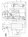
- the vaporizer-condenser 4 overcomes the middle column pressure 2 to form a first erected structure 16 of which the top is formed by the vaporizer-condenser 4.
- This structure 16 is surrounded by an insulation envelope thermal 17 (in phantom), which maintains perlite not shown around the structure 16, forming a cold box with the same reference number.
- the low pressure column 3 is arranged above the mixing column 5 to form a second structure erected 19 or main structure.
- a connecting skirt 20 connect columns 3 and 5 while maintaining the head of the column 5 spaced from the tank of column 3.
- the second structure 19 is surrounded by an envelope thermal insulation 21 (in phantom), which maintains perlite not shown around the structure 19, in forming a cold box with the same reference digital.
- the heat exchangers 7 and 8 have have been positioned to facilitate the representation of so that the cold box 17 is of relative dimensions, compared to the cold box 21, more important than in reality. In reality, these exchangers 7 and 8 are placed so as to optimize the compactness of the box cold 17 that contains them.
- the two structures 16 and 19 are arranged one at side of the other, the lower part (bottom in the figure 1) of the vaporizer-condenser 4 being arranged substantially at an intermediate level between the head of the middle column pressure 2 and the low pressure column tank 3.
- the air to be distilled, previously compressed by the compressor 9 and purified by device 10, is then divided in two streams.
- a first flow crosses the main exchange line thermal 6 by cooling down to the vicinity of its dew point.
- this first stream is itself divided into two flow, one of which is injected into the tank of the middle column pressure 2 and the other of which is injected, after expansion in an expansion valve 22, at the bottom of the mixing column 5.
- the second stream of compressed and purified air is compressed by compressor 11, then cooled to a temperature intermediate by partially crossing the line main heat exchange 6, and finally relaxed to the crossing of the turbine 12. This second flow is then introduced at an upper intermediate level of the column low pressure 3.
- the vaporizer-condenser 4 vaporizes oxygen liquid, about 98% purity, from the tank of the low pressure column 3 by condensing nitrogen at the top of the medium pressure column 2.
- a pipe 24 sends liquid oxygen from the bottom column tank pressure 3 to the vaporizer-condenser 4, and a line 25 returns the oxygen vaporized from the vaporizer-condenser 4 to the tank in column 3.
- the layout a part of the vaporizer-condenser 4 at a level located below that of the low pressure column tank 3 and above that of the head of the medium pressure column 2 allows the circulation, on the one hand, of liquid oxygen towards the vaporizer-condenser 4 and, on the other hand, top nitrogen condensed towards the head of the medium pressure column 2, under the effect of gravity, without using a pump.
- the provision of at least part of the vaporizer-condenser 4 at one level intermediate between the head of the medium pressure column 2 and the tank of the low pressure column 3 allows minimize the pumping means necessary for circulation of these liquids, regardless of the type of vaporizer-condenser 4 used, namely bath, runoff liquid oxygen (vaporizer-condenser called film) ...
- LR "rich liquid” oxygen enriched air
- medium pressure tank 2 is sub-cooled to the passage of the auxiliary heat exchanger 7, then expanded in an expansion valve 26 and finally injected into the aforementioned upper intermediate level of the lower column pressure 3.
- LP "poor liquid” (almost pure nitrogen), taken from the head of the medium pressure column 2, is sub-cooled at the crossing of the auxiliary heat exchanger 7, then relaxed in an expansion valve 27 and finally injected at the top of the low pressure column 3.
- Impure or "residual" NR nitrogen withdrawn from top of the low pressure column 3, is heated in a first time crossing the heat exchanger auxiliary 7, then in a second step across the main heat exchange line 6.
- a mixing column is a column that has the same structure than a distillation column but that is used to mix close to reversibility a relatively volatile gas, introduced at its base, and a less volatile liquid introduced at the top. Such a mixture produces cooling energy and therefore reduces energy consumption related to distillation.
- a column is for example described in document FR-A-2 143 986. In the present case, this mixture is used, by addition, to directly produce impure oxygen under a pressure slightly lower than that prevailing in the medium pressure column 2.
- liquid oxygen coming from the tank of the low pressure column 3, is withdrawn from the vaporizer-condenser 4, then pumped by pump 13, and reheated on passing through the auxiliary heat exchanger 8. This liquid oxygen is then introduced at the head of the mixing column 5.
- a second liquid rich in oxygen is taken in tank of mixing column 5 then sub-cooled to crossing of the auxiliary heat exchanger 8.
- the second rich liquid is finally expanded in an expansion valve 29 before being introduced at a lower intermediate level of the low pressure column 3.
- Air enriched with oxygen, in liquid form, is withdrawn from an intermediate level of the column mixture 5 then sub-cooled on passing through the exchanger auxiliary thermal 8. This liquid is finally expanded in an expansion valve 30 before being introduced at the level above-mentioned upper intermediate of the low pressure column 3.
- Impure oxygen gas about 95% pure, is taken from the top of the mixing column and then reheated at the crossing of the main heat exchange line 6 and distributed through a production line 31.
- the mixing column can be fed at the head by several composition liquid flows different.
- the cold boxes 17 and 21 were prefabricated in workshop then transported, erected and connected functionally on site, then filled with perlite to train installation 1.
- Prefabrication of the main cold box 21 is not dependent on the manufacture of the vaporizer-condenser 4 since the latter is not part of the main structure 19.
- a company manufacturing columns 2, 3 and 5 can completely build the cold box 21 and practically cold box 17 pending delivery of vaporizer-condenser 4.
- the construction of the cold box 17 can be substantially advanced before this delivery, for example by assembling the middle column pressure 2, the side walls and the bottom of the envelope of thermal insulation 17. All that remains is to mount the vaporizer-condenser 4 above the middle column pressure 2 and to complete the construction of the envelope 17.
- the invention therefore achieves the goals set by beginning of description by providing a reliable installation, economical and making it possible to ensure prefabrication and therefore more reduced construction.
- This last advantage is due to the possibility of working in masked time, i.e. the possibility of advancing substantially the construction of cold boxes during the construction of the vaporizer-condenser 4.
- the second structure 19 can include, in place of or in addition to the mixing column 5, a cryogenic liquid storage tank, in particular liquid oxygen, a so-called Etienne condenser column intermediate (described for example in document US-A-2 699 046) or with head condenser, a section of a column for producing impure argon known as the mixing column, or any other cryogenic fluid containment element disposed under the low pressure column 3.
- a cryogenic liquid storage tank in particular liquid oxygen
- a so-called Etienne condenser column intermediate described for example in document US-A-2 699 046
- head condenser a section of a column for producing impure argon known as the mixing column, or any other cryogenic fluid containment element disposed under the low pressure column 3.
- Such an element of confinement of cryogenic fluid ensures a relative positioning of the low pressure column 3 and the vaporizer-condenser 4 allowing the circulation of oxygen liquid from the tank in column 3 to the evaporator-condenser 4 by minimizing the use of means of
- the tank of the low pressure column 3 can be find substantially at the same level or above the vaporizer-condenser 4.
- Figure 2 illustrates a variant in which a cryogenic fluid storage tank 32 is placed under the mixing column 5 to form the main structure 19.
- the bottom of the tank 32 is at the same level than the tank of the medium pressure column 2.
- the tank 32 is, for example, a buffer capacity for storing liquid oxygen from the tank of the low pressure column 2.
- the low pressure column 3 is arranged on a skirt of support to form the second erected structure 19.
- These embodiments apply, for example, to air distillation plants which have only one double air distillation column and no mixed.
- the double columns include a low pressure column with a single vaporizer-condenser which is used to condense the nitrogen in the medium pressure column by heat exchange with the column tank liquid low pressure.
- the invention applies also in the case where the nitrogen in the middle column pressure is condensed by heat exchange with a liquid intermediate of the low pressure column, the tank being vaporized by heat exchange with air, compressed nitrogen or a medium pressure column gas less volatile than nitrogen.
- two vaporizer-condensers can be used.
Landscapes
- Engineering & Computer Science (AREA)
- Physics & Mathematics (AREA)
- Mechanical Engineering (AREA)
- Thermal Sciences (AREA)
- General Engineering & Computer Science (AREA)
- Separation By Low-Temperature Treatments (AREA)
Abstract
Description
- l'élément de confinement de fluide cryogénique comprend une colonne de mélange ;
- l'installation comprend des moyens d'envoi d'air vers la cuve de la colonne de mélange, des moyens d'envoi d'un fluide riche en oxygène vers la tête de la colonne de mélange et une conduite de production d'oxygène impur gazeux soutiré de la tête de la colonne de mélange ; et
- l'élément de confinement de fluide cryogénique comprend un réservoir de stockage d'un fluide cryogénique, notamment d'oxygène liquide
- l'élément de confinement de fluide est une colonne d'argon alimentée à partir de la colonne basse pression, une colonne opérant à une pression intermédiaire entre la basse .pression et la moyenne pression ou un échangeur de chaleur
- la colonne basse pression et l'élément de confinement sont solidaires.
- il n'y aucun moyen de distillation au-dessus de la colonne moyenne pression.
- la figurè 1 est une vue schématique d'une installation selon l'invention, et
- la figure 2 est une vue schématique partielle des parties inférieures des boítes froides d'une variante de l'installation de la figure 1.
- une double colonne de distillation qui comporte une colonne moyenne pression 2, une colonne basse pression 3 et un vaporiseur-condenseur 4, par exemple du type à bain,
- une colonne de mélange 5,
- une ligne principale d'échange thermique 6,
- deux échangeurs thermiques auxiliaires 7 et 8,
- un compresseur principal d'air 9,
- un appareil d'épuration d'air par adsorption 10,
- un compresseur auxiliaire d'air 11 couplé à une turbine de détente d'air 12, et
- une pompe 13.
Claims (9)
- Installation (1) de distillation d'air du type comprenant une double colonne de distillation qui comporte elle-même une colonne moyenne pression (2), une colonne basse pression (3), un vaporiseur-condenseur (4) de mise en relation d'échange thermique d'un gaz calorigène avec le liquide de cuve de la colonne basse pression et un élément de confinement de fluide cryogénique (5) autre que le vaporiseur-condenseur, la colonne basse pression étant à coté de la colonne moyenne pression, la cuve de la colonne basse pression étant au-dessus de la cuve de la colonne moyenne pression et le vaporiseur-condenseur (4) étant disposé au-dessus de la colonne moyenne pression (2), la colonne basse pression (3) étant disposée au-dessus de cet élément de confinement (5) et la cuve de la colonne basse pression (3) se trouvant au même niveau que la tête de la colonne moyenne pression (2) ou au-dessus de ce niveau.
- Installation selon la revendication 1, caractérisée en ce que l'élément de confinement de fluide cryogénique comprend une colonne de mélange (5).
- Installation selon la revendication 2, caractérisée en ce que l'installation (1) comprend des moyens d'envoi d'un fluide riche en oxygène vers la tête de la colonne de mélange, des moyens d'envoi de fluide moins riche en oxygène vers la cuve de la colonne de mélange et une conduite (31) de production d'oxygène impur gazeux soutiré de la tête de la colonne de mélange.
- Installation selon la revendication 1, caractérisée en ce que l'élément de confinement de fluide cryogénique comprend un réservoir (32) de stockage d'un fluide cryogénique, notamment d'oxygène liquide.
- Installation selon la revendication 1, dans laquelle l'élément de confinement de fluide est une colonne d'argon alimentée à partir de la colonne basse pression, une colonne opérant à une pression intermédiaire entre la basse pression et la moyenne pression ou un échangeur de chaleur.
- Installation selon une des revendications précédentes dans laquelle la colonne basse pression et l'élément de confinement sont solidaires.
- Installation selon l'une des revendications précédentes dans laquelle il n'y a aucun moyen de distillation au-dessus de la colonne moyenne pression (2).
- Installation selon l'une quelconque des revendications 1 à 7, comprenant l'élément de confinement de fluide cryogénique surmonté de la colonne basse pression (3,5)et non pas la colonne moyenne pression surmontée de vaporiseur-condenseur (2,4), entourés d'une enveloppe d'isolation thermique (21) de l'installation et par une deuxième boíte froide (17) contenant la colonne moyenne pression surmontée du vaporiseur-condenseur, et non pas l'élément de confinement de fluide cryogénique, surmonté de la colonne basse pression, entourés d'une enveloppe (17) d'isolation thermique.
- Procédé de montage d'un appareil de séparation comprenant au moins une colonne moyenne pression (2), une colonne basse pression (3), un élément de confinement de fluide cryogénique (5) surmonté par la colonne basse pression, et un vaporiseur-condenseur (4) pour condenser au moins partiellement un gaz calorigène par échange de chaleur avec un liquide de la colonne basse pression dans lequel on monte les colonnes basse pression et moyenne pression l'une à côté de l'autre, de sorte que la cuve de la colonne basse pression se trouve au même niveau que la tête de la colonne moyenne pression ou au-dessus de ce chaque colonne ayant sa propre boíte froide et une fois les colonnes moyenne et basse pression montées, on monte le vaporiseur-condenseur au-dessus de la colonne moyenne pression et on termine la construction de la boíte froide de la colonne moyenne pression.
Applications Claiming Priority (3)
| Application Number | Priority Date | Filing Date | Title |
|---|---|---|---|
| FR9805532A FR2778234B1 (fr) | 1998-04-30 | 1998-04-30 | Installation de distillation d'air et boite froide correspondante |
| FR9805532 | 1998-04-30 | ||
| PCT/FR1999/000997 WO1999057497A1 (fr) | 1998-04-30 | 1999-04-27 | Installation de distillation d'air et boite froide correspondante |
Publications (2)
| Publication Number | Publication Date |
|---|---|
| EP1078212A1 EP1078212A1 (fr) | 2001-02-28 |
| EP1078212B1 true EP1078212B1 (fr) | 2003-07-02 |
Family
ID=9525933
Family Applications (1)
| Application Number | Title | Priority Date | Filing Date |
|---|---|---|---|
| EP99915849A Expired - Lifetime EP1078212B1 (fr) | 1998-04-30 | 1999-04-27 | Installation de distillation d'air et boite froide correspondante |
Country Status (10)
| Country | Link |
|---|---|
| US (1) | US6167723B1 (fr) |
| EP (1) | EP1078212B1 (fr) |
| JP (1) | JP2002513908A (fr) |
| KR (1) | KR100585247B1 (fr) |
| AU (1) | AU745671B2 (fr) |
| BR (1) | BR9910080B1 (fr) |
| CZ (1) | CZ302387B6 (fr) |
| DE (1) | DE69909288T2 (fr) |
| FR (1) | FR2778234B1 (fr) |
| WO (1) | WO1999057497A1 (fr) |
Cited By (1)
| Publication number | Priority date | Publication date | Assignee | Title |
|---|---|---|---|---|
| EP3971504A1 (fr) | 2020-09-21 | 2022-03-23 | L'Air Liquide Société Anonyme pour l'Etude et l'Exploitation des Procédés Georges Claude | Appareil et procédé de séparation d'air par distillation cryogénique |
Families Citing this family (12)
| Publication number | Priority date | Publication date | Assignee | Title |
|---|---|---|---|---|
| DE10040391A1 (de) * | 2000-08-18 | 2002-02-28 | Linde Ag | Tieftemperaturluftzerlegungsanlage |
| US6397631B1 (en) * | 2001-06-12 | 2002-06-04 | Air Products And Chemicals, Inc. | Air separation process |
| EP1318367B2 (fr) * | 2001-12-04 | 2009-11-11 | Air Products And Chemicals, Inc. | Procédé et dispositif de séparation d'air cryogénique |
| DE10229663A1 (de) * | 2002-07-02 | 2004-01-22 | Linde Ag | Coldboxblechmantel |
| GB0307404D0 (en) * | 2003-03-31 | 2003-05-07 | Air Prod & Chem | Apparatus for cryogenic air distillation |
| FR2861841B1 (fr) * | 2003-11-04 | 2006-06-30 | Air Liquide | Procede et appareil de separation d'air par distillation cryogenique |
| FR2860286A1 (fr) * | 2004-01-12 | 2005-04-01 | Air Liquide | Procede de separation d'air par distillation cryogenique |
| FR2913758B3 (fr) * | 2007-03-12 | 2009-11-13 | Air Liquide | Procede et appareil de separation d'air par distillation cryogenique |
| PL2553370T3 (pl) | 2010-03-26 | 2019-11-29 | Linde Ag | Urządzenie do niskotemperaturowej separacji powietrza |
| DE102010012920A1 (de) | 2010-03-26 | 2011-09-29 | Linde Aktiengesellschaft | Vorrichtung zur Tieftemperaturzerlegung von Luft |
| DE102012008415A1 (de) * | 2012-04-27 | 2013-10-31 | Linde Aktiengesellschaft | Transportables Paket mit einer Coldbox, Tieftemperatur-Luftzerlegungsanlage und Verfahren zum Herstellen einer Tieftemperatur-Luftzerlegungsanlage |
| DE102024001541A1 (de) * | 2024-05-11 | 2025-11-13 | Linde Gmbh | Luftzerlegungsanlage mit spezieller räumlicher Anordnung und Verfahren zur Tieftemperaturzerlegung von Luft |
Family Cites Families (15)
| Publication number | Priority date | Publication date | Assignee | Title |
|---|---|---|---|---|
| NL68365C (fr) * | 1947-10-22 | 1900-01-01 | ||
| FR2143986A5 (fr) * | 1971-02-01 | 1973-02-09 | Air Liquide | |
| JPH0731002B2 (ja) * | 1987-12-21 | 1995-04-10 | 日本酸素株式会社 | 空気液化分離装置 |
| FR2670278B1 (fr) * | 1990-12-06 | 1993-01-22 | Air Liquide | Procede et installation de distillation d'air en regime variable de production d'oxygene gazeux. |
| FR2677667A1 (fr) * | 1991-06-12 | 1992-12-18 | Grenier Maurice | Procede d'alimentation d'un haut-fourneau en air enrichi en oxygene, et installation de reduction de minerai de fer correspondante. |
| JPH05187764A (ja) * | 1992-01-09 | 1993-07-27 | Kobe Steel Ltd | 空気分離装置 |
| FR2695714B1 (fr) * | 1992-09-16 | 1994-10-28 | Maurice Grenier | Installation de traitement cryogénique, notamment de distillation d'air. |
| FR2706025B1 (fr) * | 1993-06-03 | 1995-07-28 | Air Liquide | Installation de distillation d'air. |
| GB9405071D0 (en) * | 1993-07-05 | 1994-04-27 | Boc Group Plc | Air separation |
| GB9325648D0 (en) * | 1993-12-15 | 1994-02-16 | Boc Group Plc | Air separation |
| US5442925A (en) * | 1994-06-13 | 1995-08-22 | Air Products And Chemicals, Inc. | Process for the cryogenic distillation of an air feed to produce a low to medium purity oxygen product using a single distillation column system |
| GB9414938D0 (en) * | 1994-07-25 | 1994-09-14 | Boc Group Plc | Air separation |
| US5454227A (en) * | 1994-08-17 | 1995-10-03 | The Boc Group, Inc. | Air separation method and apparatus |
| US5490391A (en) * | 1994-08-25 | 1996-02-13 | The Boc Group, Inc. | Method and apparatus for producing oxygen |
| US5649433A (en) * | 1995-06-29 | 1997-07-22 | Daido Hoxan Inc. | Cold evaporator |
-
1998
- 1998-04-30 FR FR9805532A patent/FR2778234B1/fr not_active Expired - Fee Related
-
1999
- 1999-04-27 JP JP2000547416A patent/JP2002513908A/ja active Pending
- 1999-04-27 BR BRPI9910080-0A patent/BR9910080B1/pt not_active IP Right Cessation
- 1999-04-27 KR KR1020007011914A patent/KR100585247B1/ko not_active Expired - Fee Related
- 1999-04-27 WO PCT/FR1999/000997 patent/WO1999057497A1/fr not_active Ceased
- 1999-04-27 DE DE69909288T patent/DE69909288T2/de not_active Expired - Lifetime
- 1999-04-27 AU AU34286/99A patent/AU745671B2/en not_active Ceased
- 1999-04-27 CZ CZ20004024A patent/CZ302387B6/cs not_active IP Right Cessation
- 1999-04-27 EP EP99915849A patent/EP1078212B1/fr not_active Expired - Lifetime
- 1999-04-30 US US09/302,995 patent/US6167723B1/en not_active Expired - Lifetime
Cited By (2)
| Publication number | Priority date | Publication date | Assignee | Title |
|---|---|---|---|---|
| EP3971504A1 (fr) | 2020-09-21 | 2022-03-23 | L'Air Liquide Société Anonyme pour l'Etude et l'Exploitation des Procédés Georges Claude | Appareil et procédé de séparation d'air par distillation cryogénique |
| FR3114382A1 (fr) | 2020-09-21 | 2022-03-25 | L'air Liquide, Societe Anonyme Pour L'etude Et L'exploitation Des Procedes Georges Claude | Appareil de séparation d’air par distillation cryogénique à trois colonnes dont deux colonnes concentriques |
Also Published As
| Publication number | Publication date |
|---|---|
| CZ20004024A3 (en) | 2001-05-16 |
| US6167723B1 (en) | 2001-01-02 |
| DE69909288T2 (de) | 2004-04-22 |
| AU3428699A (en) | 1999-11-23 |
| AU745671B2 (en) | 2002-03-28 |
| BR9910080B1 (pt) | 2008-11-18 |
| KR100585247B1 (ko) | 2006-06-01 |
| EP1078212A1 (fr) | 2001-02-28 |
| BR9910080A (pt) | 2000-12-26 |
| FR2778234B1 (fr) | 2000-06-02 |
| DE69909288D1 (de) | 2003-08-07 |
| FR2778234A1 (fr) | 1999-11-05 |
| WO1999057497A1 (fr) | 1999-11-11 |
| CZ302387B6 (cs) | 2011-04-27 |
| KR20010043048A (ko) | 2001-05-25 |
| JP2002513908A (ja) | 2002-05-14 |
Similar Documents
| Publication | Publication Date | Title |
|---|---|---|
| EP1078212B1 (fr) | Installation de distillation d'air et boite froide correspondante | |
| EP0531182B1 (fr) | Procédé et installation de distillation d'air, et application a l'alimentation en gaz d'une aciérie | |
| EP0689019B1 (fr) | Procédé et installation de production d'oxygène gazeux sous pression | |
| EP0628778B1 (fr) | Procédé et unité de fourniture d'un gaz sous pression à une installation consommatrice d'un constituant de l'air | |
| EP0713069B1 (fr) | Procédé et installation de séparation d'air | |
| EP0605262B1 (fr) | Procédé et installation de production d'oxygène gazeux sous pression | |
| EP0848220B1 (fr) | Procédé et installation de fourniture d'un débit variable d'un gaz de l'air | |
| EP0229803B1 (fr) | Procede et installation de distillation d'air | |
| FR2774753A1 (fr) | Installation de distillation d'air comprenant plusieurs unites de distillation cryogenique de meme nature | |
| EP1552230A1 (fr) | Procede et installation de production d oxygene et de gaz ra res par distillation cryogenique d air | |
| EP0430803B1 (fr) | Procédé et installation de distillation d'air avec production d'argon | |
| US6182470B1 (en) | Air distillation plant and corresponding cold box | |
| EP0410831B1 (fr) | Installation de distillation d'air produisant de l'argon | |
| EP1143216A1 (fr) | Procédé et appareil de production d'un fluide enrichi en oxygène par distillation cryogénique | |
| EP0952415A1 (fr) | Procédé et installation de distillation d'air avec production variable d'argon | |
| FR2780147A1 (fr) | Installation de distillation d'air et boite froide correspondante | |
| EP1966554B1 (fr) | Appareil de séparation d'air par distillation cryogénique | |
| EP3812675B1 (fr) | Procédé et appareil de séparation d'air par distillation cryogénique | |
| FR2761897A1 (fr) | Installation de separation d'un melange gazeux par distillation | |
| WO2008110732A2 (fr) | Procédé et appareil de séparation d'air par distillation cryogénique | |
| FR2777641A1 (fr) | Procede et installation de distillation d'air avec production d'argon | |
| FR2795496A1 (fr) | Appareil et procede de separation d'air par distillation cryogenique | |
| FR2861841A1 (fr) | Procede et appareil de separation d'air par distillation cryogenique | |
| FR2764681A1 (fr) | Procede et installation de separation d'air par distillation cryogenique | |
| FR2787562A1 (fr) | Procede et installation de distillation d'air avec production d'argon |
Legal Events
| Date | Code | Title | Description |
|---|---|---|---|
| PUAI | Public reference made under article 153(3) epc to a published international application that has entered the european phase |
Free format text: ORIGINAL CODE: 0009012 |
|
| 17P | Request for examination filed |
Effective date: 20001130 |
|
| AK | Designated contracting states |
Kind code of ref document: A1 Designated state(s): DE FR GB |
|
| 17Q | First examination report despatched |
Effective date: 20011029 |
|
| RAP1 | Party data changed (applicant data changed or rights of an application transferred) |
Owner name: L'AIR LIQUIDE, S.A. A DIRECTOIRE ET CONSEIL DE SUR |
|
| GRAH | Despatch of communication of intention to grant a patent |
Free format text: ORIGINAL CODE: EPIDOS IGRA |
|
| GRAH | Despatch of communication of intention to grant a patent |
Free format text: ORIGINAL CODE: EPIDOS IGRA |
|
| GRAA | (expected) grant |
Free format text: ORIGINAL CODE: 0009210 |
|
| AK | Designated contracting states |
Designated state(s): DE FR GB |
|
| REG | Reference to a national code |
Ref country code: GB Ref legal event code: FG4D Free format text: NOT ENGLISH |
|
| REF | Corresponds to: |
Ref document number: 69909288 Country of ref document: DE Date of ref document: 20030807 Kind code of ref document: P |
|
| GBT | Gb: translation of ep patent filed (gb section 77(6)(a)/1977) | ||
| PLBE | No opposition filed within time limit |
Free format text: ORIGINAL CODE: 0009261 |
|
| STAA | Information on the status of an ep patent application or granted ep patent |
Free format text: STATUS: NO OPPOSITION FILED WITHIN TIME LIMIT |
|
| 26N | No opposition filed |
Effective date: 20040405 |
|
| PGFP | Annual fee paid to national office [announced via postgrant information from national office to epo] |
Ref country code: GB Payment date: 20130418 Year of fee payment: 15 Ref country code: DE Payment date: 20130419 Year of fee payment: 15 |
|
| PGFP | Annual fee paid to national office [announced via postgrant information from national office to epo] |
Ref country code: FR Payment date: 20130515 Year of fee payment: 15 |
|
| REG | Reference to a national code |
Ref country code: DE Ref legal event code: R119 Ref document number: 69909288 Country of ref document: DE |
|
| GBPC | Gb: european patent ceased through non-payment of renewal fee |
Effective date: 20140427 |
|
| REG | Reference to a national code |
Ref country code: FR Ref legal event code: ST Effective date: 20141231 |
|
| REG | Reference to a national code |
Ref country code: DE Ref legal event code: R119 Ref document number: 69909288 Country of ref document: DE Effective date: 20141101 |
|
| PG25 | Lapsed in a contracting state [announced via postgrant information from national office to epo] |
Ref country code: GB Free format text: LAPSE BECAUSE OF NON-PAYMENT OF DUE FEES Effective date: 20140427 Ref country code: DE Free format text: LAPSE BECAUSE OF NON-PAYMENT OF DUE FEES Effective date: 20141101 |
|
| PG25 | Lapsed in a contracting state [announced via postgrant information from national office to epo] |
Ref country code: FR Free format text: LAPSE BECAUSE OF NON-PAYMENT OF DUE FEES Effective date: 20140430 |