EP1078795B1 - Ouverture ou fermeture d'un élément arrière d'une structure d'un véhicule - Google Patents
Ouverture ou fermeture d'un élément arrière d'une structure d'un véhiculeInfo
- Publication number
- EP1078795B1 EP1078795B1 EP00116870A EP00116870A EP1078795B1 EP 1078795 B1 EP1078795 B1 EP 1078795B1 EP 00116870 A EP00116870 A EP 00116870A EP 00116870 A EP00116870 A EP 00116870A EP 1078795 B1 EP1078795 B1 EP 1078795B1
- Authority
- EP
- European Patent Office
- Prior art keywords
- luggage space
- door
- opening
- space
- vehicle
- Prior art date
- Legal status (The legal status is an assumption and is not a legal conclusion. Google has not performed a legal analysis and makes no representation as to the accuracy of the status listed.)
- Expired - Lifetime
Links
- 238000005192 partition Methods 0.000 claims description 21
- 238000004378 air conditioning Methods 0.000 description 6
- 230000000694 effects Effects 0.000 description 6
- 238000010276 construction Methods 0.000 description 3
- 239000005357 flat glass Substances 0.000 description 2
- 230000001419 dependent effect Effects 0.000 description 1
- 238000009957 hemming Methods 0.000 description 1
Images










Classifications
-
- B—PERFORMING OPERATIONS; TRANSPORTING
- B60—VEHICLES IN GENERAL
- B60J—WINDOWS, WINDSCREENS, NON-FIXED ROOFS, DOORS, OR SIMILAR DEVICES FOR VEHICLES; REMOVABLE EXTERNAL PROTECTIVE COVERINGS SPECIALLY ADAPTED FOR VEHICLES
- B60J5/00—Doors
- B60J5/10—Doors arranged at the vehicle rear
- B60J5/101—Doors arranged at the vehicle rear for non-load transporting vehicles, i.e. family cars including vans
- B60J5/106—Doors arranged at the vehicle rear for non-load transporting vehicles, i.e. family cars including vans comprising door or part of door being moveable by a linkage system to open/close position
Definitions
- This invention relates to an opening/closing rear component structure of a vehicle for opening/closing a luggage space provided in the rear of the vehicle.
- a back door is openably/closably supported on an upper portion of the rear of a vehicle body to open/close a rear luggage space
- an opening for a rear window is formed corresponding to an upper half of this back door and a rear window is openably/closably mounted on this opening.
- the conventional structure as stated above has problems that the effect of the air-conditioning is lessened owing to intrusion of the outside air into the compartment of the vehicle because the compartment is communicated with the outside of the vehicle when the rear window is opened on air-conditioning, and there arises feeling awkward about loading, for example, dirty luggage and the like into the rear luggage space because it is not so constituted like a sedan-type vehicle as to have an independent luggage space.
- DE 196 15 440 A1 discloses a tailgate for a vehicle comprising a rigid frame and two doors hinged on the frame, building together the tailgate.
- the hinge doors can be opened/closed separately and independently from each other and integrally as a whole.
- WO 98/30 407 which discloses the preamble of the independent claim, discloses a vehicle tailgate comprising an upper section and a lower section which are joined by hinges.
- the hinges include securing parts which log behind large pins on the vehicle body, but are released from them when the lower section is raised to an open position. This enables the two sections to be raised together.
- US 4 277 097 discloses a vehicle rear deck for covering a luggage boot, formed by a removable shelf adjacent the back of the rear seat covering a part of the boot and a roller curtain which can be extended to cover the remainder of the boot.
- the shelf also carries at least one of roller blinds which can be extended to lie in front of the rear window.
- DE 41 03 651 discloses a vehicle tailgate, which is hinged on the car body's frame via parallelogram-lever type hinge means, such that the tailgate may be opened vertically upwards as well as horizontally downwards.
- an independent luggage space separated from the compartment such a luggage space as a sedan-type vehicle has
- a large luggage space in which large luggage can be loaded and unloaded easily such a luggage space as a hatchback-type vehicle has
- an opening/closing rear component structure of a vehicle for opening/closing a luggage space provided in the rear of the vehicle comprising:
- an opening/closing rear component structure of a vehicle comprising said door for the lower luggage space being mounted to said door for the upper luggage space via a link member so that said door for the lower luggage space may be opened/closed by moving vertically in parallel, whereby it becomes possible to easily open/close the door for the lower luggage space even if the space for opening/closing the door existing backward from the vehicle is small.
- the invention as set forth in Claim 1 of the present invention includes an opening/closing rear component structure of a vehicle for opening/closing a luggage space provided in the rear of the vehicle, comprising said luggage space being divided into a upper luggage space and a lower luggage space, a openable/closable door being provided to the upper luggage space and the lower luggage space respectively, and the door for the upper luggage space and the door for the lower luggage space being adapted to selectively adopt either a mode of opening/closing the door for the upper luggage space and the door for the lower luggage space integrally so that the upper luggage space and the lower luggage space may be opened/closed at the same time, or a mode of opening/closing the door for the lower luggage space independently so that the lower luggage space may be opened/closed.
- said door for the upper luggage space is being openably/closably supported on a vehicle body via a hinge means
- said door for the lower luggage space is being openably/closably supported on the door for the upper luggage space via a hinge means, as characterized in the characterizing portion of claim 1.
- the invention as set forth in Claim 3 of the present invention includes an opening/closing rear component structure of a vehicle, comprising a partition member being provided to separate the upper luggage space from the lower luggage space, said partition member being provided movably relative to a vehicle body, and said partition member being adapted to selectively adopt either a mode of separating the upper luggage space from the lower luggage space, or a mode of making both of these luggage spaces communicable with each other.
- the invention as set forth in Claim 3 of the present invention includes an opening/closing rear component structure of a vehicle, comprising the upper portion of said door for the lower luggage space being mounted to said door for the upper luggage space via a link member so that said door for the lower luggage space may be opened/closed by moving vertically in parallel.
- the upper luggage space and the lower luggage space when the door for the upper luggage space and the door for the lower luggage space are integrally opened/closed , the upper luggage space and the lower luggage space can be opened/closed at the same time (a mode of integrally opening/closing).
- the luggage space corresponding to the door is opened/closed (the mode of independently opening/closing).
- this invention has advantages that it becomes possible to selectively use either an independent luggage space separated from the compartment or a large luggage space in which large luggage can be loaded and unloaded easily, and when the independent luggage space opened/closed it becomes also possible to keep the air-conditioning from lessening its effect, and also possible to store, for example, dirty luggage and the like in the independent luggage space.
- the door for the upper luggage space is being openably/closably supported on the vehicle body by a hinge means
- the door for the lower luggage space is being openably/closably supported on the door for the upper luggage space by a hinge means as characterized in the characterizing portion of claim 1, and has advantages that it becomes possible to load and unload large luggage in a large luggage space by opening/closing the door for the lower luggage space integrally with the door for the upper luggage space when the door for the upper luggage space is opened/closed, and to load and unload luggage in the independent luggage space ( the lower luggage space ) separated from the compartment when the door for the lower luggage space is opened/closed.
- the invention as set forth in Claim 2 of the present invention has advantages that it becomes possible to use the lower luggage space as an independent luggage space when the luggage space is separated by the partition member provided movably relative to the vehicle body ( in the mode of separating the luggage spaces ), and it becomes possible to form one large communicable luggage space out of the upper and lower luggage spaces when the upper luggage space and the lower luggage space are made communicable by the partition member.
- the invention has an advantage that small articles can be loaded and unloaded to the lower luggage space from the compartment, thus improving the availability of the luggage spaces.
- the invention as set forth in Claim 3 of the present invention has advantages that, it becomes possible to easily open/close the door for the lower luggage space even if a space for opening/closing the door existing backward from the vehicle is small as said door for the lower luggage space is opened/closed by moving vertically in parallel as a function of the link member.
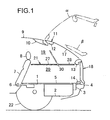
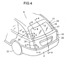
- FIG.1 through 4 show an opening/closing rear component structure of a vehicle, and in FIG.1 through 4, a concave secret box 2 is formed one step below in the rear portion of a rear floor 1, and at the same time in the rear of the secret box 2, a rear cross member 3 is formed extending in the direction of the width of the vehicle, and a rear bumper 4 is fitted to the rear cross member 3.
- a floor mat 5 is provided to cover the opening of said secret box 2 and the surface of the rear floor 1, while a headrest 8 is mounted on a seat back 7 of a rear seat which is made movable slantways with the supporting point 6 as pivotal axis.
- a rear header 10 extending in the direction of the width of the vehicle is jointed at the rear end of the roof panel 9, and a main door ( a door for a upper luggage space, so-called main gate) 11 is openably/closably supported on the upper portion of this rear header 10 as the supporting point.
- This main door 11 formed in shape in rear view includes an upper frame portion 12, a middle frame portion 13, a lower frame portion 14, and right and left side frame portions 15, 16, and a rear window glass 17 is mounted on the upper opening portion of the shaped opening, and a sub door ( a door for a lower luggage space, so-called sub gate ) 18 is openably/closably supported on the lower opening portion of the shaped opening with its upper portion as the supporting point.
- a sub door a door for a lower luggage space, so-called sub gate
- a rear luggage space is also formed surrounded by said elements 7,8,9,11 and18, and this rear luggage space is divided into a upper luggage space 19 and a lower luggage space 20.
- a package tray 21 as a partition member to separate the upper luggage space from the lower luggage space is adapted to be movable relative to the vehicle body in such a construction that it moves in association with the seat back 7 or is only detachable.
- said main door 11 and sub door 18 are adapted to selectively adopt either a mode of opening/closing both doors 11 and 18 integrally as shown with a phantom line ⁇ in FIG.1 through 3 so that the upper luggage space 19 and the lower luggage space 20 may be opened/closed at the same time ( a mode of integrally opening/closing ), or a mode of independently opening/closing only the sub door 18 as shown with a phantom line ⁇ in FIG.1 through 3 so that the lower luggage space 20 may be opened/closed (a mode of independently opening/closing ).
- the package tray 21 as a partition member is so adapted, as shown in FIG.1, to selectively adopt either a mode of separating the luggage space into the upper luggage space 19 and the lower luggage space 20 ( a mode of separating luggage spaces ) or a mode of communicating both luggage spaces 19 and 20 with each other ( a mode of communicating luggage spaces ) as shown in FIG.2 and 3.
- 22 indicates a rear wheel
- 23 indicates a rear combination lamp
- 24 indicates a rear pillar.
- a tray frame 26 in shape in plane view is provided to be jointed with the back portion of the right and left seat backs 7, 7 via hinge meanss 25,25 and a front tray 27 and a rear tray 28 are also provided on the aperture of this tray frame 26, jointing the back side of the base portion 26a of the tray frame 26 extending in the direction of the width of the vehicle with the front side of the front tray 27 by hinge meanss 29, 29 and also jointing the rear end of the front tray 27 with the front end of the rear tray 28 by a plurality of hinges 30,30--.
- Guide rollers 32, 32 are rotatably provided on the rear outer surfaces of right and left leg portions 26b, 26b of the tray frame 26 through arms 31, 31 extending outwardly in the direction of the width of the vehicle, respectively.
- guide rails 33, 33 in shape and slanted in a low-in-front, high-in-rear fashion are installed to the vehicle body as shown with a phantom line in FIG.3 and 5, and each guide groove of the right and left guide rails 33, 33 is positioned opposite to each other, and each guide roller 32, 32 is positioned rotatably within each groove.
- the tray frame 26 is dragged forward by the seat back 7 as the guide rollers 32 are guided by the guide rails 33, and when the seat back 7 has been completely slanted forward, the package tray 21 is located on the top surface of the seat back 7, being nearly flattened on the floor mat 5 and making it possible to use an ample space formed on the top surface of the seat back 7 and the top surface of the floor mat 5 for a large luggage space as shown in FIG 3.
- FIG. 6 is a sectional view taken in the direction of arrows along the line A-A of FIG.4,
- FIG. 7 is a sectional view taken in the direction of arrows along the line B-B of FIG.4,
- FIG. 8 is a sectional view taken in the direction of arrows along the line C-C of FIG.4,
- FIG. 9 is a sectional view taken in the direction of arrows along the line D-D of FIG. 4, and
- FIG. 10 is a sectional view taken in the direction of arrows along the line E-E of FIG.4.
- the main door 11 is openably/closably supported at its under surface of the upper frame portion 12 on the rear concave portion of the roof panel 9 above the rear header 10 via a hinge means 37 consisting of a fixed bracket 34, a movable bracket 35, and a hinge pin 36.
- a striker 38 is fixed to each lower outer surface of the right and left frame portions 15, 16 (only the frame portion 15 is illustrated ) of said main door 11, and an electromagnetic locking device 39 to lock and unlock the striker 38 is mounted on the body side corresponding to this striker 38.
- dampers 40, 40 to give an assist force for opening/closing to the main door 11 are spanned between the right and left frame portions 15,16 and the main door 11, respectively.
- the supporting structure and the opening/closing mechanism of the sub door 18 on the main door 11 are formed as shown in FIG.9 and 10.
- Said sub door 18 has an outer panel 41 and an inner panel 42 hemming jointed around their periphery each other, a bracket 43 for pivotally jointing a link is fixedly jointed to the lower front surface of the inner panel 42, and a hinge bracket 44 in shape in plane view is fixedly jointed to the frame portion 15 of the main door.
- a first link 47 is spanned between a pin 45 on the hinge bracket 44 and a pin 46 on the upper protruded portion of the bracket 43
- a second link 50 is spanned between a pin 48 on the hinge bracket 44 and a pin 49 on the lower protruded portion of the bracket 43.
- a damper 51 to give an assist force for opening/closing to the sub door 18 is spanned between the first link 47 and the hinge bracket 44 in the midsection in the direction of the width of the vehicle between the first link 47 and the second link 50, and a link-type hinge mechanism 52 is composed of these elements 43 through 51 to move the sub door 18 vertically in parallel so that the door can be opened/closed.
- a link-type hinge mechanism 52 is composed of these elements 43 through 51 to move the sub door 18 vertically in parallel so that the door can be opened/closed.
- a striker 53 is fixed to the lower surface of the middle frame portion 13 of the main door 11, a locking device 54 to lock and unlock the striker 53 is fitted to the inner panel 42 of the sub door 18 corresponding to this striker 53, while an outer handle 55 to unlock the locking device 54 is fitted to the outer panel 41 of the sub door 18.
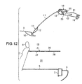
- the main door 11 and the sub door 18 may be integrally operated to swing upwardly with the hinge means 37 as the supporting point and both of these doors 11 and 18 can be opened integrally as shown in FIG. 11 and 12.
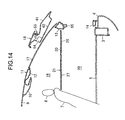
- the sub door 18 may be moved upwardly in parallel with two pins 45, 48 as supporting points along the moving trail of the pins 46 and 49 on the movable ends of the first link 47 and the second link 50 so that only the sub door 18 can be opened as shown in FIG.13 and 14.
- the upper luggage space 19 and the lower luggage space 20 may be opened/closed at the same time as shown in FIG. 11 and 12 (the mode of integrally opening/closing ) when the door for the upper luggage space 19 ( referring to the main door 11 ) and the door for the lower luggage space 20 ( referring to the sub door 18 ) are integrally opened/closed.
- the luggage space 20 corresponding to the sub door 18 is opened/closed independently as shown in FIG.13 and 14 (the mode of independently opening/closing ) when the lower luggage space 20 is opened/closed by independently opening/closing the sub door 18.
- the embodiment has advantages that it becomes possible to selectively use either an independent luggage space separated from the compartment or a large luggage space in which large luggage can be loaded and unloaded easily, and it becomes possible to keep the air-conditioning from lessening its effect when the independent luggage space is opened/closed, and possible to store, for example, dirty baggage and the like in the independent luggage space.
- the embodiment has advantages that as the door for the upper luggage space 19 ( referring to the main door 11 ) is openably/closably supported on the vehicle body by the hinge means 37 and the door for the lower luggage space 20 ( referring to the sub door 18 ) is openably/closably supported on the door for the upper luggage space 19 ( referring to the main door 11 ) by the hinge means ( referring to the link-type hinge mechanism 52 ), it becomes possible to load and unload large luggage in the large luggage space by opening/closing the door for the lower luggage space 20 ( referring to the sub door 18 ) integrally with the door for the upper luggage space when the door of the upper luggage space 19 is opened/closed, and to load and unload luggage in the independent luggage space ( referring to the lower luggage space 20 ) separated from the compartment when the door for the lower luggage space 20 ( referring to the sub door 18 ) is opened/closed.
- the embodiment has advantages that it becomes possible to use the lower luggage space 20 as an independent luggage space (the mode of separating the luggage spaces ) when the upper luggage space 19 is separated from the lower luggage space 20 by the partition member provided movably relative to the vehicle body, and it becomes possible to form one large communicable luggage space out of the upper and lower luggage spaces 19,20 (the mode of communicable luggage spaces ) when the upper luggage space 19 and the lower luggage space 20 are made communicable with each other by the partition member ( referring to package tray 21 ) as shown in FIG. 2 and 3.
- the embodiment also has advantages that when opening/closing the rear tray 28 as shown by a phantom line in FIG.1, it becomes possible to load and unload small articles from the compartment into the lower luggage space 20, improving the availability.
- the embodiment has advantages that it becomes possible to open/close the door for the lower luggage space 20 referring to the sub door 18) easily even if the space for opening/closing the door existing backward from the vehicle is small, as the door for said lower luggage space 20 ( referring to the sub door 18 ) is moved vertically in parallel as a function of the link member ( referring to the link-type hinge mechanism ) to open/close.
- FIG. 15 shows an example of an opening/closing rear component structure of a vehicle not covered by the attached set of claims, wherein the upper portion of the sub door 18 for the lower luggage space 20 is openably/closably supported on the back side of the middle frame portion 13 via a hinge means 56.
- FIG.16 through 30 show other alternative embodiment of an opening/closing rear component structure of a vehicle. Also in this embodiment, a detailed explanation is omitted, by giving the same numerals to the same or similar portions as in the preceding embodiments.
- a luggage board 60 ( referring to FIG. 16 ) on the side of the vehicle body is formed detachably relative to the vehicle body and a luggage board 61 on the side of the door is secured to the middle frame portion 13 and is formed movably relative to the vehicle body, and the luggage space in the rear of a vehicle is separated into the upper luggage space 19 and the lower luggage space 20 (the so-called luggage room space ) by both of these luggage boards 60 and 61( partition members ).
- 62 shown in FIG.23 is a seal rubber to seal between the luggage boards 60 and 61, and this seal rubber 62 is fitted to the underside of the front end of the luggage board 61.
- 63 in FIG.16 indicates a floor.
- FIG.17 is a partial perspective view of the vehicle body, and the main door 11 is openably/closably supported via the hinge means 37 ( referring to FIG.21 ) on the hinge fixture portion 64 of the body.
- FIG.18 is a partial perspective view of the main door 11 formed similarly in shape in rear view as in the preceding embodiments, and a rear window glass 17 is mounted on the upper opening portion65 of the shape, while the sub door 18 shown in FIG.19 is openably/closably supported on the lower opening portion 66 of the shape.
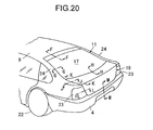
- FIG.20 is a partial perspective view of the vehicle taken from an upper rearward position
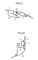
- FIG.21 is a sectional view taken in the direction of arrows along the line F-F of FIG.20
- FIG.22 is a sectional view taken in the direction of arrows along the line G-G of FIG.20
- FIG.23 is a sectional view taken in the direction of arrows along the line H-H of FIG.20
- FIG.24 is a sectional view taken in the direction of arrows along the line J-J of FIG.20
- FIG.25 is a sectional view taken in the direction of arrows along the line K-K of FIG.20
- FIG.26 is a sectional view taken in the direction of arrows along the line L-L of FIG.20
- FIG.27 is a sectional view taken in the direction of arrows along the line M-M of FIG.20.
- the sub door 18 is openably/closably mounted via link-type hinge mechanism 67 on the right side and on the left side of the middle portion 13 of the main door 11. But only the link-type hinge mechanism 67 on the left side is shown in the figure, but the link-type hinge mechanism 67 on the right side is formed symmetrical.
- This link-type hinge mechanism 67 is so formed as shown in FIG.25 and 29.
- a hinge bracket 68 is secured to the main door 11, whereas the hinge bracket 69 also secured to the sub door 18.
- pins 70, 71, and 72 are provided to the hinge bracket 68 on the main door 11 as pivots when opening/closing the sub door 18, and a first link 74 is spanned between the front pin 70 on the hinge bracket 68 and a front pin73 on the hinge bracket 69 on the sub door 18.
- a second link 76 is spanned between the middle pin 71 and a middle pin75 on the hinge bracket 69 on the sub door 18.
- damper 51 to give an assist force for opening/closing the sub door 18 is spanned between the rear pin 72 and a rear pin 77 on the hinge bracket 69 on the sub door 18.
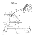
- the main door 11 and the sub door 18 may be integrally operated to swing upwardly with the hinge means 37 ( referring to Fig. 21 ) as the supporting point and both of these doors 11 and 18 can be opened integrally as shown in FIG. 28.
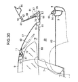
- the sub door 18 may be moved upwardly and then opened forwardly as shown in FIG.29 and 30 with two pins 70, 71 as supporting points along the moving trail of the pins 73 and 75 on the movable ends of the first link 74 and the second link 76.
- the upper luggage space 19 and the lower luggage space 20 may be opened/closed at the same time (the mode of integrally opening/closing ) when the door for the upper luggage space 19 ( referring to the main door 11 ) and the door for the lower luggage space 20 ( referring to the sub door 18 ) are integrally opened/closed.
- the luggage space 20 corresponding to the sub door 18 is opened/closed independently (the mode of independently opening/closing ) when the lower luggage space 20 is opened/closed by independently opening/closing only the sub door 18.
- the embodiment has advantages that it becomes possible to selectively use either an independent luggage space separated from the compartment (referring to the lower luggage space 20 ) or a large luggage space in which large luggage can be loaded and unloaded easily, and it becomes possible to keep the air-conditioning from lessening its effect when the independent luggage space is opened/closed , and possible to store, for example, dirty baggage and the like in the independent luggage space.
- the embodiment has advantages that as the door for the upper luggage space 19 ( referring to the main door 11 ) is openably/closably supported on the vehicle body by the hinge means 37 and the door for the lower luggage space 20 ( referring to the sub door 18 ) is openably/closably supported on the door for the upper luggage space 19 ( referring to the main door 11 ) by the hinge means ( referring to the link-type hinge mechanism 67 ), it becomes possible to load and unload large luggage in the large luggage space by opening/closing the door for the lower luggage space 20 ( referring to the sub door 18 ) integrally with the door for the upper luggage space when the door of the upper luggage space 19 ( referring to the main door 11 ) is opened/closed, and to load and unload luggage in the independent luggage space ( referring to the lower luggage space 20 ) separated from the compartment when the door for the lower luggage space 20 ( referring to the sub door 18) is opened/closed.
- the embodiment has advantages that it becomes possible to use the lower luggage space 20 as an independent luggage space (the mode of separating the luggage spaces ) when the upper luggage space 19 is separated from the lower luggage space 20 by the partition member (referring to the luggage board 60,61 ) provided movably relative to the vehicle body, and it becomes possible to form one large communicable luggage space out of the upper and lower luggage spaces 19,20 (the mode of communicable luggage spaces ) when the upper luggage space 19 and the lower luggage space 20 are made communicable with each other by the partition member ( referring to the luggage board 60, 61 ).
- the door for the upper luggage space in the present invention corresponds to the main door 11 of the embodiment; the same shall apply hereinafter;
- the door for the lower luggage space corresponds to the sub door 18
- the hinge means for opening/closing the door for the lower luggage space corresponds to the link-type hinge mechanism 52, 67, and the hinge means 56
- the partition member corresponds to the package tray 21, the luggage boards 60, 61
- the link member corresponds to the link-type hinge mechanism 52, but the present invention is, however, not limited to the constitution of the above mentioned embodiment.
Landscapes
- Engineering & Computer Science (AREA)
- Mechanical Engineering (AREA)
- Body Structure For Vehicles (AREA)
- Superstructure Of Vehicle (AREA)
- Vehicle Step Arrangements And Article Storage (AREA)
Claims (4)
- Structure d'élément arrière d'un véhicule s'ouvrant ou se fermant pour ouvrir ou fermer un espace pour bagages à l'arrière du véhicule, comprenant :dans laquelle ladite porte (11) de l'espace supérieur (19) pour bagages est supportée de manière ouvrable ou fermable sur le corps du véhicule par l'intermédiaire d'un premier moyen de charnière (37) et ladite porte (18) de l'espace inférieur (20) pour bagages est supportée de manière ouvrable ou fermable sur la porte (11) de l'espace supérieur (19) pour bagages par l'intermédiaire d'un deuxième moyen de charnière,ledit espace pour bagages qui est divisé en un espace supérieur (19) pour bagages et un espace inférieur (20) pour bagages,des portes ouvrantes ou fermantes (11, 18) qui sont prévues respectivement pour l'espace supérieur (19) pour bagages et l'espace inférieur (20) pour bagages, etla porte (11) de l'espace supérieur (19) pour bagages et la porte (18) de l'espace inférieur (20) pour bagages étant adaptées pour adopter sélectivement soit un mode d'ouverture ou de fermeture de la porte (11) de l'espace supérieur (19) pour bagages et de la porte (18) de l'espace inférieur (20) pour bagages de manière intégrale afin que l'espace supérieur (19) pour bagages et l'espace inférieur (20) pour bagages puissent être ouverts ou fermés en même temps soit un mode d'ouverture ou de fermeture de la porte (18) de l'espace inférieur (20) pour bagages de manière indépendante afin que l'espace inférieur (20) pour bagages puisse être ouvert ou fermé,
caractérisée en ce que ledit deuxième moyen de charnière comprend un moyen de charnière (52; 67) du type articulation ayant une première articulation (47; 74) supportée de manière pivotante par une première broche (46; 70) et une deuxième articulation (50; 76) supportée de manière pivotante par une deuxième broche (48; 71), ladite première broche (46; 70) et ladite deuxième broche (48; 71) étant séparées l'une de l'autre et en ce que lesdites première (47; 74) et deuxième (50; 76) articulations sont séparées et mobiles l'une par rapport à l'autre. - Structure d'élément arrière d'un véhicule s'ouvrant ou se fermant comme exposé dans la revendication 1, comprenant :un membre de séparation (21, 28) qui est prévu pour séparer l'espace supérieur (19) pour bagages de l'espace inférieur (20) pour bagages,ledit membre de séparation (21, 28) étant prévu pour être mobile par rapport à la carrosserie du véhicule, etledit membre de séparation (21, 28) étant adapté pour adopter sélectivement soit un mode consistant à séparer l'espace supérieur (19) pour bagages de l'espace inférieur (20) pour bagages soit un mode consistant à faire communiquer ces espaces (19, 20) pour bagages l'un avec l'autre.
- Structure d'élément arrière d'un véhicule s'ouvrant ou se fermant comme exposé dans la revendication 1 ou 2, dans laquelle
ladite porte (18) de l'espace inférieur (20) pour bagages est montée sur ladite porte (11) de l'espace supérieur (19) pour bagages par l'intermédiaire d'un membre d'articulation (52; 67) afin que ladite porte (18) de l'espace inférieur (20) pour bagages puisse être ouverte ou fermée en se déplaçant verticalement en parallèle avec la porte (11) de l'espace supérieur (19) pour bagages. - Structure d'élément arrière d'un véhicule s'ouvrant ou se fermant comme exposé dans la revendication 1 ou 2, dans laquelle
ladite porte (18) de l'espace inférieur (20) pour bagages est montée sur ladite porte (11) de l'espace supérieur (19) pour bagages par l'intermédiaire d'un membre d'articulation (52; 67) afin que ladite porte (18) de l'espace inférieur (20) pour bagages puisse être ouverte ou fermée en se déplaçant vers le haut et vers l'avant.
Applications Claiming Priority (2)
| Application Number | Priority Date | Filing Date | Title |
|---|---|---|---|
| JP23340999 | 1999-08-20 | ||
| JP23340999A JP4281163B2 (ja) | 1999-08-20 | 1999-08-20 | 車両の後部開閉体構造 |
Publications (3)
| Publication Number | Publication Date |
|---|---|
| EP1078795A2 EP1078795A2 (fr) | 2001-02-28 |
| EP1078795A3 EP1078795A3 (fr) | 2002-09-25 |
| EP1078795B1 true EP1078795B1 (fr) | 2005-04-27 |
Family
ID=16954622
Family Applications (1)
| Application Number | Title | Priority Date | Filing Date |
|---|---|---|---|
| EP00116870A Expired - Lifetime EP1078795B1 (fr) | 1999-08-20 | 2000-08-04 | Ouverture ou fermeture d'un élément arrière d'une structure d'un véhicule |
Country Status (4)
| Country | Link |
|---|---|
| US (1) | US6318782B1 (fr) |
| EP (1) | EP1078795B1 (fr) |
| JP (1) | JP4281163B2 (fr) |
| DE (1) | DE60019694T2 (fr) |
Families Citing this family (33)
| Publication number | Priority date | Publication date | Assignee | Title |
|---|---|---|---|---|
| DE60113914T2 (de) * | 2000-05-16 | 2006-07-20 | Mazda Motor Corp. | Fahrzeughinterkofferraum |
| DE10028735B4 (de) * | 2000-06-09 | 2007-09-06 | Daimlerchrysler Ag | Rahmen für insbesondere ein temporäres Einsetzen in einen offen in den Fahrgastraum eines Fahrzeuges übergehenden Kofferraum |
| US6454341B2 (en) * | 2000-06-20 | 2002-09-24 | Meritor Light Vehicle Systems, Inc. | Lift gate for a motor vehicle |
| US6485094B2 (en) * | 2000-12-06 | 2002-11-26 | Asc Incorporated | Automotive vehicle open air system |
| US6520557B2 (en) * | 2001-06-05 | 2003-02-18 | Delphi Technologies, Inc. | Power actuating system for four-bar hinge articulated vehicle closure element field of the invention |
| JP3861732B2 (ja) * | 2002-04-01 | 2006-12-20 | マツダ株式会社 | 自動車の後部荷室構造 |
| US20050179269A1 (en) * | 2004-02-12 | 2005-08-18 | Vantage Mobility International, Llc | Gated rear entry for wheelchair |
| DE102004032750A1 (de) | 2004-07-07 | 2006-02-09 | Adam Opel Ag | Mehrteilige Heckklappe für ein Kraftfahrzeug |
| US7073847B2 (en) * | 2004-09-10 | 2006-07-11 | Oshkosh Truck Corporation | Duplex door for vehicle |
| DE102005021306A1 (de) * | 2005-05-09 | 2006-11-16 | Dura Automotive Plettenberg Entwicklungs- Und Vertriebs Gmbh | Heckklappe für ein Kraftfahrzeug |
| FR2894189A1 (fr) * | 2005-12-02 | 2007-06-08 | Heuliez Sa | Portillon pour coffre |
| JP4255947B2 (ja) * | 2005-12-28 | 2009-04-22 | 本田技研工業株式会社 | 後部ドア構造及び後部ドアの組み立て方法 |
| US20070187969A1 (en) * | 2006-02-16 | 2007-08-16 | Collins & Aikman Products Co. | Cargo Storage Compartment and Access Thereto |
| DE102006032807A1 (de) * | 2006-07-14 | 2008-01-24 | Dr.Ing.H.C. F. Porsche Ag | Abdeckung für einen Gepäckraum |
| FR2907752B1 (fr) * | 2006-10-27 | 2009-01-23 | Plastic Omnium Cie | Module arriere destine a etre sur un vehicule automobile |
| CZ200783A3 (cs) * | 2007-01-31 | 2008-08-13 | Škoda Auto a. s. | Zapojení elektrického ovládání delené výklopné zádi pro vozidla |
| US20090051195A1 (en) * | 2007-08-24 | 2009-02-26 | Ford Global Technologies, Llc | Cargo access and retention system for a passenger vehicle |
| US8020912B2 (en) * | 2009-04-21 | 2011-09-20 | Ford Global Technologies, Llc | Rear closure assembly for a passenger vehicle |
| JP5152404B2 (ja) * | 2009-11-16 | 2013-02-27 | トヨタ自動車株式会社 | 上ヒンジドア構造 |
| US8353550B1 (en) * | 2011-06-29 | 2013-01-15 | Ford Global Technologies, Llc | Seating system with package tray |
| FR2983444B1 (fr) * | 2011-12-05 | 2013-12-27 | Peugeot Citroen Automobiles Sa | Vehicule ultra compact equipe d'une coque de protection des passagers arriere. |
| RU2483939C1 (ru) * | 2011-12-14 | 2013-06-10 | Андрей Семенович Орлов | Устройство для открывания угловой панели задней двери кузова автомобиля |
| US8876184B2 (en) | 2012-01-27 | 2014-11-04 | Ford Global Technologies, Llc | Package tray with cargo catchment |
| JP5900242B2 (ja) * | 2012-08-21 | 2016-04-06 | マツダ株式会社 | 車両の後部車体構造 |
| DE102015207556A1 (de) * | 2015-04-24 | 2016-10-27 | Bayerische Motoren Werke Aktiengesellschaft | Schwenkbare Kraftfahrzeugheckklappe |
| US9428944B1 (en) * | 2015-06-16 | 2016-08-30 | Ford Global Technologies, Llc | Articulating closure mechanism for non-aligned closure panels |
| US9945161B2 (en) * | 2016-03-22 | 2018-04-17 | Ford Global Technologies, Llc | Lock system for dual vehicle closures |
| JP6547716B2 (ja) * | 2016-09-26 | 2019-07-24 | トヨタ自動車株式会社 | 車両用バックドア装置 |
| US10358854B1 (en) * | 2017-04-05 | 2019-07-23 | Wudthipong Guygaew | Tailgate system for a vehicle with astride opening features |
| DE102017213949B4 (de) | 2017-08-10 | 2025-01-30 | Volkswagen Aktiengesellschaft | Schließeinrichtung für ein Kraftfahrzeug, Kraftfahrzeug |
| US20190322321A1 (en) | 2018-04-23 | 2019-10-24 | Oshkosh Corporation | Refuse body adapter |
| DE102019114990B3 (de) | 2019-06-04 | 2020-04-23 | Bayerische Motoren Werke Aktiengesellschaft | Heckklappe für einen Personenkraftwagen sowie Verfahren zum Betreiben einer Heckklappe |
| DE102022128730B4 (de) | 2022-10-28 | 2025-07-31 | Dr. Ing. H.C. F. Porsche Aktiengesellschaft | Kraftfahrzeug mit geteilter Ladeklappenanordnung |
Family Cites Families (24)
| Publication number | Priority date | Publication date | Assignee | Title |
|---|---|---|---|---|
| CA510321A (fr) * | 1955-02-22 | Briggs Manufacturing Company | Carrosserie de vehicule | |
| US2767896A (en) * | 1953-11-02 | 1956-10-23 | Clarence E Beck | Removable shelf for station wagons |
| US2889097A (en) * | 1957-08-30 | 1959-06-02 | Charles W Broehl | Automobile utility device |
| US3010760A (en) * | 1960-05-04 | 1961-11-28 | Peter C Trautmann | Retractable tail gate for station wagons |
| US3110429A (en) * | 1961-10-26 | 1963-11-12 | Fred O Philips | Removable shelf for station wagon |
| US3291520A (en) * | 1964-06-10 | 1966-12-13 | Smith Alva Merl | Station wagon utility compartment and removable cover therefor |
| US3713472A (en) * | 1971-11-17 | 1973-01-30 | Gen Motors Corp | Vehicle closure system |
| FR2431395A1 (fr) * | 1978-07-21 | 1980-02-15 | Citroen Sa | Vehicule a plage arriere amovible |
| US4413854A (en) * | 1981-10-19 | 1983-11-08 | Nissan Design International, Inc. | Dual deck construction for a hatchback type automobile |
| EP0159017B1 (fr) * | 1984-04-18 | 1990-06-13 | Mazda Motor Corporation | Structure de portière arrière pour véhicules automobiles |
| US4728141A (en) * | 1985-05-31 | 1988-03-01 | Honda Giken Kogyo Kabushiki Kaisha | Automotive rear shelf structure |
| DE4103651C1 (en) * | 1991-02-07 | 1992-08-06 | Mercedes-Benz Aktiengesellschaft, 7000 Stuttgart, De | Car boot flap linked by parallelogram leverage - has car body side two-arm lever, whose free end couples to parallelogram end |
| US5123864A (en) | 1991-04-05 | 1992-06-23 | Amp Incorporated | Coaxial contact with sleeve |
| FR2689830B1 (fr) * | 1992-04-10 | 1994-05-20 | Renault Regie Nale Usines | Vehicule dont le compartiment a bagages comporte un rideau escamotable. |
| FR2696704B1 (fr) * | 1992-10-09 | 1994-12-09 | Renault | Dispositif d'articulation d'un hayon sur un élément de carrosserie. |
| FR2703005B1 (fr) * | 1993-03-26 | 1995-06-09 | Renault | Dispositif d'articulation d'un hayon sur un élément de carrosserie. |
| DE19544590C1 (de) * | 1995-11-30 | 1997-05-07 | Stabilus Gmbh | Fahrzeug mit schwenkbarem Karosserieteil |
| US5685592A (en) * | 1995-12-21 | 1997-11-11 | United Technologies Automotive, Inc. | Cargo compartment cover and item support assembly |
| DE19615540A1 (de) * | 1996-04-19 | 1997-04-30 | Daimler Benz Ag | Personenkraftwagen mit wenigstens einem schwenkbar gelagerten Karosserieteil, insbesondere einer Heckklappe |
| GB9700611D0 (en) * | 1997-01-14 | 1997-03-05 | Rover Group | A vehicle tailgate |
| US6068327A (en) * | 1997-10-21 | 2000-05-30 | Peregrine Incorporated | Upwardly folding vehicle door assembly |
| US6050202A (en) * | 1998-07-22 | 2000-04-18 | Prince Corporation | Storage divider shelf |
| GB2340527A (en) * | 1998-08-13 | 2000-02-23 | Rover Group | Tailgate Assembly |
| US6113172A (en) * | 1998-12-22 | 2000-09-05 | Daimlerchrysler Corporation | Multi-positional vehicle shelf |
-
1999
- 1999-08-20 JP JP23340999A patent/JP4281163B2/ja not_active Expired - Fee Related
-
2000
- 2000-08-04 DE DE60019694T patent/DE60019694T2/de not_active Expired - Lifetime
- 2000-08-04 EP EP00116870A patent/EP1078795B1/fr not_active Expired - Lifetime
- 2000-08-17 US US09/640,075 patent/US6318782B1/en not_active Expired - Fee Related
Also Published As
| Publication number | Publication date |
|---|---|
| US6318782B1 (en) | 2001-11-20 |
| EP1078795A3 (fr) | 2002-09-25 |
| JP2001055169A (ja) | 2001-02-27 |
| DE60019694T2 (de) | 2006-05-04 |
| JP4281163B2 (ja) | 2009-06-17 |
| DE60019694D1 (de) | 2005-06-02 |
| EP1078795A2 (fr) | 2001-02-28 |
Similar Documents
| Publication | Publication Date | Title |
|---|---|---|
| US6318782B1 (en) | Opening/closing rear component structure of a vehicle | |
| US5398988A (en) | Vehicle door assembly | |
| US6860543B2 (en) | Mechanism for moving a door | |
| US20030218358A1 (en) | Dual mode vehicle side door | |
| EP1215080B1 (fr) | Camionette pick up | |
| US20140210234A1 (en) | Vehicle including net structure | |
| US6799788B2 (en) | Decklid mechanism for vehicle with retractable top | |
| US7104588B2 (en) | Mechanism for moving a door | |
| US20040232722A1 (en) | Midgate assembly including fixed window and crossbar | |
| US6231096B1 (en) | Cargo space covering for a cargo space of a motor vehicle | |
| CA3142961A1 (fr) | Fonctionnement de porte modifie pour un vehicule motorise | |
| EP1549519B1 (fr) | Mecanisme de couvercle de coffre pour vehicule decapotable | |
| CN117944770A (zh) | 具有带贯通开口的中间门的车辆总成和货物容纳方法 | |
| JP4305105B2 (ja) | 車両用バックドア構造 | |
| JP3700651B2 (ja) | 自動車用トランク構造 | |
| JP2004189162A (ja) | 車両の後部荷室構造 | |
| JP4622190B2 (ja) | 車両の上部開閉体構造 | |
| JPH06191436A (ja) | 自動車のボディ構造 | |
| JPH0746578Y2 (ja) | 自動車のトノボード | |
| US6499794B1 (en) | Sport utility sliding door | |
| JP4089336B2 (ja) | 車両のスライドドア構造 | |
| JPH0351206Y2 (fr) | ||
| KR100888764B1 (ko) | 커버링 쉘프의 힌지 구조 | |
| JP3533933B2 (ja) | 車両の箱型ボデーの庇 | |
| JPH03121925A (ja) | 車両のドア開閉構造 |
Legal Events
| Date | Code | Title | Description |
|---|---|---|---|
| PUAI | Public reference made under article 153(3) epc to a published international application that has entered the european phase |
Free format text: ORIGINAL CODE: 0009012 |
|
| AK | Designated contracting states |
Kind code of ref document: A2 Designated state(s): AT BE CH CY DE DK ES FI FR GB GR IE IT LI LU MC NL PT SE |
|
| AX | Request for extension of the european patent |
Free format text: AL;LT;LV;MK;RO;SI |
|
| PUAL | Search report despatched |
Free format text: ORIGINAL CODE: 0009013 |
|
| AK | Designated contracting states |
Kind code of ref document: A3 Designated state(s): AT BE CH CY DE DK ES FI FR GB GR IE IT LI LU MC NL PT SE |
|
| AX | Request for extension of the european patent |
Free format text: AL;LT;LV;MK;RO;SI |
|
| 17P | Request for examination filed |
Effective date: 20030116 |
|
| 17Q | First examination report despatched |
Effective date: 20030313 |
|
| AKX | Designation fees paid |
Designated state(s): DE ES FR |
|
| RBV | Designated contracting states (corrected) |
Designated state(s): DE FR GB |
|
| GRAP | Despatch of communication of intention to grant a patent |
Free format text: ORIGINAL CODE: EPIDOSNIGR1 |
|
| RIN1 | Information on inventor provided before grant (corrected) |
Inventor name: KIKUCHI, REIJI, C/O MAZDA MOTOR CORPORATION Inventor name: SUZUKI, TOSHIFUMI, C/O MAZDA MOTOR CORPORATION Inventor name: WATANABE, MASAYA, C/O MAZDA MOTOR CORPORATION Inventor name: KIRITA, TAKAMI,C/O MAZDA MOTOR CORPORATION |
|
| GRAS | Grant fee paid |
Free format text: ORIGINAL CODE: EPIDOSNIGR3 |
|
| GRAA | (expected) grant |
Free format text: ORIGINAL CODE: 0009210 |
|
| AK | Designated contracting states |
Kind code of ref document: B1 Designated state(s): DE FR GB |
|
| REG | Reference to a national code |
Ref country code: GB Ref legal event code: FG4D |
|
| REG | Reference to a national code |
Ref country code: IE Ref legal event code: FG4D |
|
| REF | Corresponds to: |
Ref document number: 60019694 Country of ref document: DE Date of ref document: 20050602 Kind code of ref document: P |
|
| PG25 | Lapsed in a contracting state [announced via postgrant information from national office to epo] |
Ref country code: GB Free format text: LAPSE BECAUSE OF NON-PAYMENT OF DUE FEES Effective date: 20050804 |
|
| PLBE | No opposition filed within time limit |
Free format text: ORIGINAL CODE: 0009261 |
|
| STAA | Information on the status of an ep patent application or granted ep patent |
Free format text: STATUS: NO OPPOSITION FILED WITHIN TIME LIMIT |
|
| 26N | No opposition filed |
Effective date: 20060130 |
|
| GBPC | Gb: european patent ceased through non-payment of renewal fee |
Effective date: 20050804 |
|
| EN | Fr: translation not filed | ||
| PG25 | Lapsed in a contracting state [announced via postgrant information from national office to epo] |
Ref country code: FR Free format text: LAPSE BECAUSE OF NON-PAYMENT OF DUE FEES Effective date: 20050831 |
|
| PG25 | Lapsed in a contracting state [announced via postgrant information from national office to epo] |
Ref country code: FR Free format text: LAPSE BECAUSE OF NON-PAYMENT OF DUE FEES Effective date: 20050427 |
|
| PGFP | Annual fee paid to national office [announced via postgrant information from national office to epo] |
Ref country code: DE Payment date: 20110727 Year of fee payment: 12 |
|
| PG25 | Lapsed in a contracting state [announced via postgrant information from national office to epo] |
Ref country code: DE Free format text: LAPSE BECAUSE OF NON-PAYMENT OF DUE FEES Effective date: 20130301 |
|
| REG | Reference to a national code |
Ref country code: DE Ref legal event code: R119 Ref document number: 60019694 Country of ref document: DE Effective date: 20130301 |