EP1215080B1 - Camionette pick up - Google Patents
Camionette pick up Download PDFInfo
- Publication number
- EP1215080B1 EP1215080B1 EP01118740A EP01118740A EP1215080B1 EP 1215080 B1 EP1215080 B1 EP 1215080B1 EP 01118740 A EP01118740 A EP 01118740A EP 01118740 A EP01118740 A EP 01118740A EP 1215080 B1 EP1215080 B1 EP 1215080B1
- Authority
- EP
- European Patent Office
- Prior art keywords
- panel member
- cab
- box
- box panel
- pick
- Prior art date
- Legal status (The legal status is an assumption and is not a legal conclusion. Google has not performed a legal analysis and makes no representation as to the accuracy of the status listed.)
- Expired - Lifetime
Links
Images


Classifications
-
- B—PERFORMING OPERATIONS; TRANSPORTING
- B60—VEHICLES IN GENERAL
- B60P—VEHICLES ADAPTED FOR LOAD TRANSPORTATION OR TO TRANSPORT, TO CARRY, OR TO COMPRISE SPECIAL LOADS OR OBJECTS
- B60P3/00—Vehicles adapted to transport, to carry or to comprise special loads or objects
- B60P3/40—Vehicles adapted to transport, to carry or to comprise special loads or objects for carrying long loads, e.g. with separate wheeled load supporting elements
Definitions
- the present invention relates to a pick up truck that transports light cargo, and more particularly, to a pick up truck that can stably load a longer cargo by increasing the size of a cargo box.
- a pick up truck in accordance with the features of the claims 1 and 2, respectively, is known from JP-A-11314581 which corresponds to US-B-6478355.
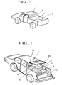
- FIG 1 is a perspective view illustrating a rear side structure of a related art pick up truck.
- the related art pick up truck includes a cab portion 1 for carrying passengers and a cargo box 2 for carrying cargo.
- a side wall 4 is compartmented between the cab portion 1 and the cargo box 2.
- the side wall 4 is provided with a glass window 3 to allow a driver to ensure a rear view through a room mirror (not shown).
- the related art pick up truck cannot transport a longer cargo than the length of the cargo box 2. Therefore, to transport a longer cargo, although it is light, a truck more than a medium size has been required whether the cargo is light or heavy. This has increased the transport cost.
- Such a pick up truck includes a cab portion 1, the cargo box 2, a box panel member 7, and a front side wall 8.
- the box panel member 7 is axially connected with the front side wall 8 of the cargo box 2 and is movable in a horizontal position.
- box panel member 7 is partially overlapped with the wheel cover 5 and is supported by the wheel cover 5.
- the cargo box 2 when the box panel member 7 is in a horizontal position, the cargo box 2 includes a cargo box opening 9. Also, a cab panel member 9a is axially mounted in the cab portion 1 and is movable between a vertical closed state and a horizontal open state.
- the related art pick up truck can increase the size of the cargo box by opening the cab panel member and the box panel member as the case may be so as to load a longer cargo.
- the related art pick up truck has several problems.
- the box panel member since the cab panel member and the box panel member separated from each other are unfolded toward the cargo box, the box panel member is put on the wheel cover. In this case, the box panel member does not require a separate support member but the cab panel member requires a relatively expensive shock absorber to maintain the horizontal state. This increases the production cost.
- the box panel member since the box panel member is put on the wheel cover, the box panel member is not flush with the bottom. This causes unstable load state in case of a longer cargo.
- the present invention is directed to a pick up truck that substantially obviates one or more of the problems due to limitations and disadvantages of the related art.
- An object of the present invention is to provide to a pick up truck in which a cab panel member and a box panel member can be folded toward a cab portion in a state where they are separated from each other, so that the box panel member is flush with a bottom surface of a cargo box.
- Another object of the present invention is to provide a pick up truck in which a rear seat is not damaged even if a longer cargo is loaded in a state where a box panel member is folded.
- Another object of the present invention is to provide a pick up truck in which a cab panel member is only folded toward a cab portion to conveniently open a cab opening, thereby ventilating the inside of the pick up truck.
- a pick up truck according to the present invention includes the features as defined in claim 1 and 2, respectively.
- the cab panel member 30 and the box panel member 40 are separated from each other and folded toward an inner portion of the cab portion 10, it is convenient to use them.
- the box panel member is flush with the bottom surface of the cargo box in a state where it is folded, it is convenient to load a longer cargo S and a rear seat is not damaged.
- FIG 3 is a perspective view illustrating a pick up truck in accordance with the present invention, in which a cab panel member 30 and a box panel member 40 are folded toward an inner portion of a cab portion 10 in a state where they are separated from each other.
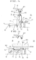
- FIGs. 4A and 4B illustrate a pick up truck in accordance with the first embodiment of the present invention.
- the cab panel member 30 and the box panel member 40 are separated from each other and folded by a hinge at a boundary between them.
- a hinge 41 is rotatably fixed to a supporter 42 at a bottom surface of the cab portion 10. Accordingly, to load a longer cargo S, as shown in FIG 4B. the lower portion of the box panel member 40 is folded in a state where the cab panel member 30 is overlapped with the box panel member 40, so that an opening 100 is formed to connect a cargo load portion 20 with the cab portion 10.
- the cab panel member 30 is maintained so as not to be folded in a vertically closed state and a cab panel member locking means 60 for releasing a locking state when the cab panel member 30 is folded is rotatably mounted.
- a seat folding means should be provided so as not to affect movement of the box panel member 40.
- a rear seat 14 and a seat back portion 15 disposed at the rear of the driver's seat in two rows are formed to be folded around pivot shafts 16 and 17.
- the rear seat 14 is raised and the seat back portion 15 moves correspondingly, so that the box panel member 40 is folded to be put on the seat back portion 15, thereby extending the length of the cargo load portion 20 to the inner portion of the cab portion 10.
- a panel member supporter 50 is provided on a bottom surface 19 of a cargo box to firmly maintain the state of the box panel member 40 raised to close the opening 100. That is to say, a stopper 51 is fixably mounted at one side of the box panel member 40 to firmly support the raised state of the box panel member 40 at one side opposite to a direction in which the box panel member 40 is folded.
- a weather strip w1 that maintains tightness with the cab panel member 30 is mounted at an end portion of the lock panel 11 so that rainwater is prevented from being entered into the cab portion 10 along edges of the cab panel member 30 and the box panel member 40 having mobility.
- a weather strip w2 that maintains tightness with a contact portion between the cab panel member 30 and the box panel member 40 is mounted on the box panel member 40.
- a weather strip w3 is mounted in a contact portion between the stopper 51 and the box panel member 40.
- the cab portion 10 and the cargo load portion 20 are compartmented and a plurality of weather strips w1, w2, and w3 maintain tightness. Accordingly, it is possible to prevent any noise from occurring during driving of the pick up truck and to also prevent rainwater or dust from being entered into the cab portion 10.
- the opening 100 in a closed state should be opened.
- the rear seat 14 which is unfolded is raised in an arrow direction to maintain a vertical state and at the same time the seat back portion 15 is pulled back counterclockwise so that it is folded toward the rear seat 14.
- a locking member 61 of the cab panel member locking means 60 is separated and moved from its state which supports the inner side end of the cab panel member 30.
- the cab panel member locking means 60 is released.
- the locking member 61 is swingably mounted at the base of the lock panel 11.
- the locking member 61 is configured to have more powerful fixed force at the location where it is closely contacted with the cab panel member 30 and the swing location at both ends where the close contact is released.
- the cab panel member 30 is closely contacted with the box panel member 40 by inwardly folding the cab panel member 30 connected with the box panel member 40 by the hinge 31. Then, the box panel member 40 is inwardly pushed, so that the box panel member 40 is put on the seat back portion 15 in a state where the box panel member 40 is overlapped with the cab panel member 30. As a result, as shown in FIG. 4b, the box panel member 40 is flush with a bottom surface of a load floor 21.
- the opening 100 closed by the cab panel member 30 and the box panel member 40 is opened, so that the longer cargo S can stably be loaded using an upper surface of the box panel member 40 and the load floor 21.
- the box panel member 40 and the cab panel member 30 are raised contrary to the above operation and the locking member 61 of the cab panel member locking means 60 moves to support the inner side end of the cab panel member 30. Then, the rear seat 14 and the seat back portion 15 are returned to their original location so that the inner portion of the cab portion 10 is sealed and the cargo load 20 is compartmented.
- FIGs. 5A and 5B illustrate another pick up truck according to the second embodiment of the present invention.
- a cab panel member 30 is closely contacted with the base of a lock panel 11 in a state where a cab panel member 30 and a box panel member 40 are completely separated from each other.
- the box panel member 40 moves to be put on a portion where a rear seat 14 and a seat back portion 15 are folded, so as to form an opening 100.
- the cab panel member 30 and the box panel member 40 are separated from each other in a horizontal direction.
- the cab panel member 30 is formed to be folded together with an end of the lock panel 11 by a hinge 31 while the box panel member 40 is formed to be folded with a supporter 42 raised on a bottom surface 19 of a cargo box by a hinge 41.
- a fixing means 70 consisting of a pair of hooks 71 and 72 is mounted in the lock panel 11 to maintain the opening 100 in an open state in a state where the cab panel member 30 is tightly folded.
- a seat folding means is provided so as not to affect movement of the box panel member 40 in the same manner as the first embodiment.
- the rear seat 14 and the seat back portion 15 disposed at the rear of the driver's seat in two rows are mounted to be folded around pivot shafts 16 and 17.
- the rear seat 14 is raised and the seat back portion 15 moves correspondingly, so that the box panel member 40 is folded to be put on the seat back portion 15, thereby extending the length of a cargo load portion 20 to the inner portion of the cab portion 10.
- a panel member supporter 50 is provided on the bottom surface 19 of the cargo box to firmly maintain the state of the box panel member 40 raised to close the opening 100. That is to say, a stopper 51 is fixably mounted at one side of the box panel member 40 to support the raised state of the box panel member 40. Thus, the stopper 51 firmly supports the raised state of the box panel member 40 at one side opposite to a direction in which the box panel member 40 is folded.
- a weather strip w1 that maintains tightness with the cab panel member 30 is mounted at an end portion of the lock panel 11 so that rainwater is prevented from being entered into the cab portion 10 along edges of the cab panel member 30 and the box panel member 40 having mobility.
- a weather strip w2 that maintains tightness with a contact portion between the cab panel member 30 and the box panel member 40 is mounted on the box panel member 40.
- a weather strip w3 is mounted in a contact portion between the stopper 51 and the box panel member 40.
- the opening 100 is closed.
- the cab portion 10 and the cargo load portion 20 are compartmented like a typical pick up truck. Tightness is maintained between the cab panel member 30 and the box panel member 40 by means of several weather strips w1, w2, and w3. Therefore, it is possible to prevent any noise from occurring during driving of the pick up truck and to also prevent rainwater or dust from being entered into the cab portion 10.
- the opening 100 in a closed state should be opened.
- the rear seat 14 which is unfolded is raised in an arrow direction to maintain a vertical state and at the same time the seat back portion 15 is pulled back counterclockwise so that the seat back portion 15 is folded toward the rear seat 14.
- the cab panel member 30 is inwardly raised and is closely fixed to the lock panel 11 by the fixed means 70. Then, the box panel member 40 is inwardly pushed, so that the box panel member 40 is put on the seat back portion 15. Therefore, as shown in FIG. 5b, the box panel member 40 is flush with a bottom surface of a load floor 21. As a result, the longer cargo can stably be loaded using the box panel member 40 and the load floor 21.
- the rear seat 14 and the seat back portion 15 are only folded in a state where the cab panel member 30 is not opened.
- the box panel member 40 is only folded toward the cab portion 10 to load the longer cargo.
- the cab panel member 30 is only folded toward the inner side of the cab portion 10 to ventilate the inner portion during driving of the pick up truck.
- the pick up truck according to the present invention has the following advantages.
- the box panel member is put on the folded seat back portion so that it is flush with the bottom surface of the cargo box. Accordingly, it is convenient to stably load the longer cargo.
- the seat back portion is mounted at the rear seat, it is possible to prevent a passenger sit on the rear seat from spring out of the truck through the cab opening and the opening of the cargo box even if any crash occurs.
- a pick up truck in which a longer cargo can stably be loaded as the case may be by increasing the size of a cargo box.
- the pick up truck includes: a cab portion 10 driven by an engine and provided with seats at the front to allow a driver and passengers to ride thereon, having a top portion covered with a lock panel 11; a cargo load portion 20 having a load floor 21 extended toward a rear end of the cab portion 10, for loading various cargos on the load floor 21; a cab panel member 30 and a box panel member 40 raised between the cab portion 10 and the cargo load portion 20 to divide the cab portion 10 and the cargo load portion 20, having a back glass to see the rear; and a box panel switch means for switching the box panel member 40 to connect the cab portion 10 with the cargo load portion 20, so that an opening 100 is formed to extend the cargo load portion 20, wherein the box panel switch means separates the cab panel member 30 from the box panel member 40, so that hinges 31 and 41 are formed to allow the cab panel member 30 and the box panel member 40 to be
Landscapes
- Engineering & Computer Science (AREA)
- Health & Medical Sciences (AREA)
- Public Health (AREA)
- Transportation (AREA)
- Mechanical Engineering (AREA)
- Body Structure For Vehicles (AREA)
- Fittings On The Vehicle Exterior For Carrying Loads, And Devices For Holding Or Mounting Articles (AREA)
- Seal Device For Vehicle (AREA)
Claims (5)
- Camionnette pick-up comprenant :une partie formant cabine (10) munie de sièges à l'avant pour permettre à un conducteur et à des passagers de se déplacer dans celle-ci et ayant une partie supérieure couverte d'un panneau de fermeture (11) ;une partie de chargement de cargaison (20) ayant un plancher de chargement (21) s'étendant vers une extrémité arrière de la partie formant cabine (10) pour charger différentes cargaisons sur le plancher de chargement (21) ;un élément formant panneau de cabine (30) et un élément formant panneau de caisse (40) s'élevant entre la partie formant cabine (10) et la partie de chargement de cargaison (20) pour diviser la partie formant cabine et la partie de chargement de cargaison et ayant une vitre arrière pour voir l'arrière ; etdes moyens de manoeuvre ou de commutation de panneau de caisse pour manoeuvrer l'élément de panneau de caisse (40) afin de connecter la partie formant cabine (10) à la partie de chargement de cargaison (20), de sorte qu'une ouverture (100) est formée pour agrandir la partie de chargement de cargaison (20),dans laquelle les moyens de manoeuvre du panneau de caisse séparent l'élément formant panneau de cabine (30) de l'élément formant panneau de caisse (40), moyennant quoi des charnières (41) sont formées pour permettre à l'élément formant panneau de caisse (40) d'être plié vers un côté intérieur de la partie formant cabine (10), etdans laquelle des moyens de support d'élément de panneau (50) sont prévus pour soutenir l'élément formant le panneau de caisse (40) dans sa position élevée et maintiennent et conservent l'état élevé dans lequel l'intérieur de la partie formant cabine (10) et la partie de chargement de cargaison (20) sont compartimentés, c'est-à-dire séparés l'un de l'autre,caractérisée en ce que l'élément formant panneau de cabine (30) est connecté à l'élément formant panneau de caisse (40) par des charnières (31) pour permettre à l'élément formant panneau de cabine (30) d'être plié sur l'élément formant panneau de caisse (40) vers le côté intérieur de la partie formant cabine (10), et en ce que des moyens de verrouillage de l'élément formant panneau de cabine (60) sont prévus pour libérer un état de verrouillage de l'élément formant panneau de cabine (30) et comprennent un élément de verrouillage (61) monté de manière orientable au niveau de la base du panneau de fermeture (11), l'élément de verrouillage (61) étant configuré pour avoir une force fixe ou stationnaire plus puissante au niveau de l'endroit où il est en contact étroit avec l'élément formant panneau de cabine (30) et l'endroit de rotation au niveau des deux extrémités où le contact étroit est libéré.
- Camionnette pick-up selon le préambule de la revendication 1,
caractérisée en ce que l'élément formant panneau de cabine (30) est relié au panneau de fermeture (11) par des charnières (31) pour permettre à l'élément formant panneau de cabine (30) d'être plié vers le côté intérieur de la partie formant cabine (10), et en ce que le panneau de fermeture (11) comprend un moyen fixe (70) constitué d'une paire de crochets (71, 72) pour maintenir l'ouverture (100) dans un état ouvert dans un état où l'élément formant panneau de cabine (30) est fermement plié. - Camionnette pick-up selon la revendication 1 ou 2, comprenant en outre des moyens de pliage de siège pour faire tourner un siège arrière (14) et une partie de dossier de siège (15) disposée à l'arrière d'un siège de conducteur, vers le côté intérieur de la partie formant cabine (10), pour mettre l'élément formant panneau de caisse (40) sur la partie de dossier de siège (15).
- Camionnette pick-up selon l'une quelconque des revendications précédentes, dans laquelle les moyens de soutien d'élément de panneau (50) comprennent un arrêt (51) monté de manière fixe au niveau d'un côté de l'élément formant panneau de caisse (40) pour soutenir l'élément formant panneau de caisse (40) au niveau d'un côté opposé à la direction dans laquelle l'élément formant panneau de caisse (40) est plié.
- Camionnette pick-up selon l'une quelconque des revendications précédentes, comprenant en outre des caoutchoucs d'étanchéité (w1, w2, w3) disposés le long de l'élément formant panneau de cabine (30) et de l'élément formant panneau de caisse (40) pour maintenir l'étanchéité.
Applications Claiming Priority (4)
| Application Number | Priority Date | Filing Date | Title |
|---|---|---|---|
| KR2000075758 | 2000-12-13 | ||
| KR10-2000-0075758A KR100397935B1 (ko) | 2000-12-13 | 2000-12-13 | 소형 수송트럭 |
| KR10-2000-0075757A KR100373653B1 (ko) | 2000-12-13 | 2000-12-13 | 소형 수송트럭 |
| KR2000075757 | 2000-12-13 |
Publications (3)
| Publication Number | Publication Date |
|---|---|
| EP1215080A2 EP1215080A2 (fr) | 2002-06-19 |
| EP1215080A3 EP1215080A3 (fr) | 2003-02-12 |
| EP1215080B1 true EP1215080B1 (fr) | 2007-05-02 |
Family
ID=26638619
Family Applications (1)
| Application Number | Title | Priority Date | Filing Date |
|---|---|---|---|
| EP01118740A Expired - Lifetime EP1215080B1 (fr) | 2000-12-13 | 2001-08-07 | Camionette pick up |
Country Status (6)
| Country | Link |
|---|---|
| US (1) | US6447039B1 (fr) |
| EP (1) | EP1215080B1 (fr) |
| JP (1) | JP2002187576A (fr) |
| CN (1) | CN1162287C (fr) |
| DE (1) | DE60128199T2 (fr) |
| MY (1) | MY127177A (fr) |
Families Citing this family (30)
| Publication number | Priority date | Publication date | Assignee | Title |
|---|---|---|---|---|
| KR20020050622A (ko) * | 2000-12-21 | 2002-06-27 | 이계안 | 스포츠 유틸리티 트럭의 미드게이트 하단 차제 구조물 |
| JP2005507826A (ja) * | 2001-11-07 | 2005-03-24 | ジョンソン コントロールズ テクノロジー カンパニー | 車両用の座席と荷台のシステム |
| JP2003191868A (ja) * | 2001-12-26 | 2003-07-09 | Fuji Heavy Ind Ltd | 開閉パネルのロック構造 |
| JP2003191870A (ja) * | 2001-12-27 | 2003-07-09 | Fuji Heavy Ind Ltd | 車両の隔壁ゲート構造 |
| JP3861002B2 (ja) | 2001-12-27 | 2006-12-20 | 富士重工業株式会社 | 車両の隔壁ゲート用ウエザストリップ構造 |
| US6550849B1 (en) * | 2002-06-11 | 2003-04-22 | Ford Global Technologies, Inc. | Automotive vehicle with pass through cargo space |
| DE10233746A1 (de) * | 2002-07-24 | 2004-02-12 | Webasto Vehicle Systems International Gmbh | Rahmenelement zur Anbringung im unteren Bereich der Heckscheibe eines Fahrzeugs sowie Fahrzeug mit einem derartigen Rahmenelement |
| US7066532B2 (en) * | 2002-11-12 | 2006-06-27 | Lear Corporation | Ultrathin structural panel with rigid insert |
| US20040189052A1 (en) * | 2003-03-26 | 2004-09-30 | Heidacker Gordon M. | Extended pick-up truck cab with configurable interior cargo space |
| US6742834B1 (en) * | 2003-05-22 | 2004-06-01 | General Motors Corporation | Midgate assembly including garage door style midgate panel |
| US6786535B1 (en) * | 2003-05-22 | 2004-09-07 | General Motors Corporation | Vertically and horizontally split midgate assembly |
| US6796600B1 (en) * | 2003-05-22 | 2004-09-28 | General Motors Corporation | Vehicle body with pre-hung midgate panel |
| US6899367B1 (en) * | 2003-12-30 | 2005-05-31 | Mitsubishi Jidosha Kogyo Kabushiki Kaisha | Movable seat for vehicle |
| US7066516B2 (en) * | 2004-03-31 | 2006-06-27 | Lear Corporation | Rear vehicle storage system |
| DE102005011681B4 (de) * | 2005-03-11 | 2010-11-11 | Webasto Ag | Laderaumanordnung |
| US20070296258A1 (en) * | 2006-06-23 | 2007-12-27 | Kyle Calvert | Rear seat extended fold and kneel reconfiguration |
| US20090039675A1 (en) * | 2007-08-09 | 2009-02-12 | King E Mackey | Vehicle body with passenger compartment over cargo bed |
| US8215690B2 (en) * | 2009-12-23 | 2012-07-10 | Kawasaki Jukogyo Kabushiki Kaisha | Pick-up style utility vehicle with expandable cargo bed |
| US8322770B2 (en) * | 2009-12-29 | 2012-12-04 | Kawasaki Jukogyo Kabushiki Kaisha | Pick-up style utility vehicle with expandable cargo bed |
| US8328262B2 (en) * | 2009-12-30 | 2012-12-11 | Kawasaki Jukogyo Kabushiki Kaisha | Pick-up style utility vehicle with expandable cargo bed |
| US8128144B2 (en) * | 2009-12-30 | 2012-03-06 | Kawasaki Jukogyo Kabushiki Kaisha | Pick-up style utility vehicle with expandable cargo bed |
| JP6358655B2 (ja) * | 2014-08-08 | 2018-07-18 | ヤンマー株式会社 | 運搬車 |
| GB201518004D0 (en) * | 2015-10-12 | 2015-11-25 | Microsoft Technology Licensing Llc | Audio signal processing |
| CN106741216A (zh) * | 2017-02-09 | 2017-05-31 | 武汉华智科创高新技术有限公司 | 增加空间利用率的微型汽车 |
| US11312310B2 (en) | 2019-11-27 | 2022-04-26 | Phillip Lynn Symonds | Outer truck bed side panel work bench |
| US11414137B2 (en) * | 2020-02-12 | 2022-08-16 | GM Global Technology Operations LLC | Vehicle partition and method of manufacturing a vehicle |
| US11731549B2 (en) * | 2020-02-18 | 2023-08-22 | Toyota Motor Engineering & Manufacturing North America, Inc. | Vehicle cooler with passenger cabin access |
| US12091097B2 (en) * | 2020-12-03 | 2024-09-17 | Ford Global Technologies, Llc | Pivotable cab back assembly for a vehicle and cab back assembly pivoting method |
| US11999274B2 (en) * | 2022-04-05 | 2024-06-04 | GM Global Technology Operations LLC | Vehicle having a folding mid-gate with an integrated seat |
| US20240208591A1 (en) * | 2022-12-21 | 2024-06-27 | Honda Motor Co., Ltd. | Adjustable cargo area partition for vehicle |
Family Cites Families (20)
| Publication number | Priority date | Publication date | Assignee | Title |
|---|---|---|---|---|
| US1838344A (en) * | 1929-08-19 | 1931-12-29 | Kari Keen Mfg Company Inc | Luggage carrier for automobile bodies |
| US2530097A (en) * | 1949-10-04 | 1950-11-14 | Lawrence E Troth | Pickup delivery truck |
| US3169792A (en) * | 1962-12-06 | 1965-02-16 | Viquez Carlos L Solano | Pick-up truck which is convertible into a passenger vehicle |
| US3240527A (en) * | 1964-05-13 | 1966-03-15 | Chrysler Corp | Vehicle body interior arrangement |
| US3770312A (en) * | 1971-12-23 | 1973-11-06 | Sparton Management Services In | Pickup truck cab with retractable or removable rear window |
| JPS5830877A (ja) * | 1981-08-13 | 1983-02-23 | Mazda Motor Corp | トラツクのキヤビン後部構造 |
| JPS5836930U (ja) * | 1981-09-04 | 1983-03-10 | 井関農機株式会社 | 貨物自動車 |
| US4613183A (en) * | 1982-09-27 | 1986-09-23 | Kesling Peter C | Cab and box construction for pickup truck |
| US4941702A (en) * | 1989-02-23 | 1990-07-17 | Southward James F | Underseat expansion bed vehicle for transporting long load material |
| JPH02256576A (ja) * | 1989-03-30 | 1990-10-17 | Mazda Motor Corp | 自動車のキャビン後部構造 |
| US5263757A (en) * | 1991-12-03 | 1993-11-23 | Reed Floyd W | Cargo box for insertion into the rear window of trucks |
| JPH08324459A (ja) * | 1995-06-02 | 1996-12-10 | Suzuki Motor Corp | 自動車の車体構造 |
| US5524951A (en) * | 1995-08-22 | 1996-06-11 | Johnson; Thurman | Cargo box installed integral with pickup cab to afford direct access between cab and box |
| US5934727A (en) * | 1997-07-16 | 1999-08-10 | General Motors Corporation | Adaptable pick up truck configuration |
| US6478355B1 (en) * | 1998-02-24 | 2002-11-12 | General Motors Corporation | Adaptable pick up truck configuration |
| JP2000071830A (ja) * | 1998-08-28 | 2000-03-07 | Mazda Motor Corp | 自動車の車体構造 |
| JP2000185669A (ja) * | 1998-12-22 | 2000-07-04 | Toyota Autom Loom Works Ltd | 自動車のボデー構造 |
| US6186575B1 (en) * | 1999-06-11 | 2001-02-13 | General Motors Corporation | Re-configurable cargo cover |
| US6234560B1 (en) * | 1999-08-13 | 2001-05-22 | General Motors Corporation | Cargo cover |
| US6481772B1 (en) * | 1999-10-15 | 2002-11-19 | Subaru Of America, Inc. | Vehicle having a foldable seat with a retractable window and an extending cargo bed |
-
2001
- 2001-07-24 JP JP2001223596A patent/JP2002187576A/ja active Pending
- 2001-08-02 MY MYPI20013655 patent/MY127177A/en unknown
- 2001-08-07 EP EP01118740A patent/EP1215080B1/fr not_active Expired - Lifetime
- 2001-08-07 US US09/925,045 patent/US6447039B1/en not_active Expired - Lifetime
- 2001-08-07 DE DE60128199T patent/DE60128199T2/de not_active Expired - Fee Related
- 2001-08-09 CN CNB011245859A patent/CN1162287C/zh not_active Expired - Fee Related
Also Published As
| Publication number | Publication date |
|---|---|
| EP1215080A3 (fr) | 2003-02-12 |
| EP1215080A2 (fr) | 2002-06-19 |
| DE60128199T2 (de) | 2007-12-27 |
| JP2002187576A (ja) | 2002-07-02 |
| US20020070573A1 (en) | 2002-06-13 |
| CN1358642A (zh) | 2002-07-17 |
| MY127177A (en) | 2006-11-30 |
| CN1162287C (zh) | 2004-08-18 |
| DE60128199D1 (de) | 2007-06-14 |
| US6447039B1 (en) | 2002-09-10 |
Similar Documents
| Publication | Publication Date | Title |
|---|---|---|
| EP1215080B1 (fr) | Camionette pick up | |
| US6217096B1 (en) | Passenger compartment sealing structure for automobile | |
| EP1176060B1 (fr) | Panneau intermédiaire reconfigurable utilisable dans un véhicule | |
| US6318782B1 (en) | Opening/closing rear component structure of a vehicle | |
| US8220861B2 (en) | Convertible vehicle body | |
| CN104411522A (zh) | 带尾门的车辆 | |
| JP3196159B2 (ja) | 自動車の荷物室用カバー装置 | |
| WO2014175240A1 (fr) | Véhicule | |
| EP2998141B1 (fr) | Véhicule | |
| JP6225177B2 (ja) | 車両 | |
| JP3284825B2 (ja) | 自動車の車体構造 | |
| KR100373653B1 (ko) | 소형 수송트럭 | |
| JP4210967B2 (ja) | 車両の後部車体構造 | |
| CN221067739U (zh) | 车辆尾门以及车辆 | |
| KR100397935B1 (ko) | 소형 수송트럭 | |
| KR100387834B1 (ko) | 자동차의 이중개방형 테일게이트 | |
| JP4478523B2 (ja) | コンバーチブルトップ車のトノカバー構造 | |
| KR100368381B1 (ko) | 차량의 미드게이트 갭커버 | |
| JPH0453292Y2 (fr) | ||
| JP4311835B2 (ja) | 跳ね上げ式扉の上部隅部の構造 | |
| KR200363548Y1 (ko) | 차량용 적재함 | |
| KR19980049495A (ko) | 텐트장착 침대자동차 | |
| JP2001026220A (ja) | 車両の後部開閉体構造 | |
| JPH072138U (ja) | 移動用キャビン | |
| JPH08324458A (ja) | 自動車の車体構造 |
Legal Events
| Date | Code | Title | Description |
|---|---|---|---|
| PUAI | Public reference made under article 153(3) epc to a published international application that has entered the european phase |
Free format text: ORIGINAL CODE: 0009012 |
|
| AK | Designated contracting states |
Kind code of ref document: A2 Designated state(s): AT BE CH CY DE DK ES FI FR GB GR IE IT LI LU MC NL PT SE TR |
|
| AX | Request for extension of the european patent |
Free format text: AL;LT;LV;MK;RO;SI |
|
| PUAL | Search report despatched |
Free format text: ORIGINAL CODE: 0009013 |
|
| AK | Designated contracting states |
Designated state(s): AT BE CH CY DE DK ES FI FR GB GR IE IT LI LU MC NL PT SE TR |
|
| AX | Request for extension of the european patent |
Extension state: AL LT LV MK RO SI |
|
| RIC1 | Information provided on ipc code assigned before grant |
Ipc: 7B 60P 3/40 A Ipc: 7B 60P 3/42 B |
|
| 17P | Request for examination filed |
Effective date: 20030307 |
|
| AKX | Designation fees paid |
Designated state(s): DE FR GB |
|
| GRAP | Despatch of communication of intention to grant a patent |
Free format text: ORIGINAL CODE: EPIDOSNIGR1 |
|
| GRAS | Grant fee paid |
Free format text: ORIGINAL CODE: EPIDOSNIGR3 |
|
| GRAA | (expected) grant |
Free format text: ORIGINAL CODE: 0009210 |
|
| AK | Designated contracting states |
Kind code of ref document: B1 Designated state(s): DE FR GB |
|
| REG | Reference to a national code |
Ref country code: GB Ref legal event code: FG4D |
|
| REF | Corresponds to: |
Ref document number: 60128199 Country of ref document: DE Date of ref document: 20070614 Kind code of ref document: P |
|
| ET | Fr: translation filed | ||
| PGFP | Annual fee paid to national office [announced via postgrant information from national office to epo] |
Ref country code: GB Payment date: 20070801 Year of fee payment: 7 |
|
| PLBE | No opposition filed within time limit |
Free format text: ORIGINAL CODE: 0009261 |
|
| STAA | Information on the status of an ep patent application or granted ep patent |
Free format text: STATUS: NO OPPOSITION FILED WITHIN TIME LIMIT |
|
| 26N | No opposition filed |
Effective date: 20080205 |
|
| PGFP | Annual fee paid to national office [announced via postgrant information from national office to epo] |
Ref country code: FR Payment date: 20070808 Year of fee payment: 7 |
|
| PGFP | Annual fee paid to national office [announced via postgrant information from national office to epo] |
Ref country code: DE Payment date: 20080821 Year of fee payment: 8 |
|
| GBPC | Gb: european patent ceased through non-payment of renewal fee |
Effective date: 20080807 |
|
| REG | Reference to a national code |
Ref country code: FR Ref legal event code: ST Effective date: 20090430 |
|
| PG25 | Lapsed in a contracting state [announced via postgrant information from national office to epo] |
Ref country code: FR Free format text: LAPSE BECAUSE OF NON-PAYMENT OF DUE FEES Effective date: 20080901 |
|
| PG25 | Lapsed in a contracting state [announced via postgrant information from national office to epo] |
Ref country code: GB Free format text: LAPSE BECAUSE OF NON-PAYMENT OF DUE FEES Effective date: 20080807 |
|
| PG25 | Lapsed in a contracting state [announced via postgrant information from national office to epo] |
Ref country code: DE Free format text: LAPSE BECAUSE OF NON-PAYMENT OF DUE FEES Effective date: 20100302 |