EP1079043A2 - Verbindungselement für Schalungsplatten - Google Patents
Verbindungselement für Schalungsplatten Download PDFInfo
- Publication number
- EP1079043A2 EP1079043A2 EP00117847A EP00117847A EP1079043A2 EP 1079043 A2 EP1079043 A2 EP 1079043A2 EP 00117847 A EP00117847 A EP 00117847A EP 00117847 A EP00117847 A EP 00117847A EP 1079043 A2 EP1079043 A2 EP 1079043A2
- Authority
- EP
- European Patent Office
- Prior art keywords
- connecting element
- element according
- angled
- tensioning
- angle
- Prior art date
- Legal status (The legal status is an assumption and is not a legal conclusion. Google has not performed a legal analysis and makes no representation as to the accuracy of the status listed.)
- Withdrawn
Links
Images

Classifications
-
- E—FIXED CONSTRUCTIONS
- E04—BUILDING
- E04G—SCAFFOLDING; FORMS; SHUTTERING; BUILDING IMPLEMENTS OR AIDS, OR THEIR USE; HANDLING BUILDING MATERIALS ON THE SITE; REPAIRING, BREAKING-UP OR OTHER WORK ON EXISTING BUILDINGS
- E04G17/00—Connecting or other auxiliary members for forms, falsework structures, or shutterings
- E04G17/001—Corner fastening or connecting means for forming or stiffening elements
-
- E—FIXED CONSTRUCTIONS
- E04—BUILDING
- E04G—SCAFFOLDING; FORMS; SHUTTERING; BUILDING IMPLEMENTS OR AIDS, OR THEIR USE; HANDLING BUILDING MATERIALS ON THE SITE; REPAIRING, BREAKING-UP OR OTHER WORK ON EXISTING BUILDINGS
- E04G17/00—Connecting or other auxiliary members for forms, falsework structures, or shutterings
- E04G17/02—Connecting or fastening means for non-metallic forming or stiffening elements
Definitions
- the invention relates to a connecting element for formwork panels during concreting work.
- the invention has for its object a robust and easy-to-use connecting element for formwork panels to create an exact alignment and fixation of the Formwork panels allowed at joints, both at formwork panels placed in a straight line, as with Corner connections in the form of inside and outside corners.
- one of the contact plates be designed as an angle plate, the same with a corner connection of formwork panels attached to the inside and outside angles and tightened can be and thus the correct plate angle and the exact position of the plates is guaranteed.
- the angle doesn't have to necessarily be a 90 ° angle, but can if necessary also be an obtuse or acute angle.
- an angled web As Counterpart on the other side of the plates is used for this Training an angled web, the legs of which are parallel to the angled Surfaces (roof surfaces) of the angle plate run and when clamping the plate parts in between press against the angle plate.
- the clamping can e.g. with help one through the "ridge" of the angle plate inserted tension rod, preferably in the form of a Clamping screw, done by a provided in the angle bar Hole that can be a threaded hole engages and runs in the direction of the bisector.
- the clamping element can also be used as a tie rod anchored to the angled web Wedge or other suitable clamping device, such as about a tension buckle, an eccentric-like tension lever etc.
- the hole in the angled web also can be designed without thread and the anchoring of Tension rod by means of an angled on one or two sides, through the bore protruding end.
- the hole can then e.g. be designed like a keyhole, so that Pull rod end after inserting it by a quarter turn can be locked.
- the Winkelsteg is a lost one Component that remains in the concrete. With the help of one End of the tension rod or the tie rod attached protective sleeve can be prevented that the rod is concreted.
- the abutment plates can be flat plates, which by means of Tension rod or tie rod clamped against the formwork panels become.
- they are used parallel to Ridge line of the angled slab edges as an attachment on the outer surfaces of the formwork panels, so that these aligned with each other.
- the tensioning screw runs at the joint between the two Plates through a recess worked out there and engages in the hole of the then with its two leg ends lost on the inner plate surfaces Angular web.
- the lost part can also be considered rectilinear Plate or preferably as an elongated hollow body with, for example rectangular cross section are formed, the of a receiving channel for the tension or tension rod Holes is penetrated. For a better fit in a corner connection the ends of the hollow body can be beveled in a trapezoidal shape become.
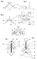
- FIGS. 1 and 2 An angle strut 2 is illustrated in FIGS. 1 and 2, which together with that shown in Figures 3 and 4 Angle plate 4 gives an angular connecting element, as shown in Fig. 5 in cross section.
- Angle brace and Angle plate are made from stamped parts in the from the cross sections bent shape according to Figures 1 and 3, wherein from the sloping roof surfaces 5 of the angle plate 4 tabs 6 are bent out at right angles, the outer edges of which Side edges of the angled strut fit and if desired can be welded to them.
- Shape and dimensions of the Tabs 6 are selected here so that the 5th remaining recesses 42 aligned in pairs and in the Form projection onto each other to form a channel cross section is suitable for inserting a railing bracket 18, as in Fig. 5 is indicated by dashed lines.
- the outer parallel edges 8 of the angle plate 4 are angled so that they are shown in the Embodiment lie in one plane and contact surfaces for the external surfaces with each other in formwork panels to be connected on the same level.
- the angle strut 2 with the angled ends 10 of their legs 12 welded the Weld points are designated by 14 in FIG. 5.
- each with one Roof surface 5 of the angle plate 4 and one leg 12 of the angle strut 2 enclosed space forms a square, here hatched channel 16 also for inclusion of a dashed line indicated railing bracket 18, as illustrated in Fig. 9 is.
- the angle strut 2 which surrounds the angle plate 4 on the outside, has a flat central part 20, in which a passage opening 22 is provided for a clamping screw 24.
- the angle plate 4 also has one at the opposite point Passage opening 26 for the clamping screw.
- the flat middle part 20 of the angle strut results in a defined contact surface for an angular web 28 used for tightening at Outside tightening screw corresponding to that in the figures 6 and 8 embodiments shown.
- a nut 32 between the angle strut and the angle plate serves as a captive device for the clamping screw 24.
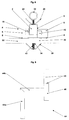
- FIG. 6 shows an application example of the connecting element according to the invention for external corner formwork.
- the two Formwork panels 30 form a right angle at a corner a ceiling to be concreted.
- the connecting element is outside placed on this corner and engages with the clamping screw 24 by a worked out at the joint of the formwork panels 30 Opening 34.
- From the inside is another thread web 36 screwed onto the clamping screw 24 with a threaded opening, which is similar to the angled web 28 and himself when tightening the connecting element with his angled side legs from the inside against the formwork panels 30 sets, as shown in FIG. 6.
- the tensioning takes place with the other angle bar 28, which is at the other end of the clamping screw 24 sits and serves as a clamping nut, being against presses the middle part 20 of the angular web 2.
- a flat one Panel connection in which the two formwork panels 30 lie in one plane, the connecting element is opposite the embodiments of Figures 6 and 7 rotated by 90 ° placed so that the two angled edges 8 of the angle plate 4 on the outside of the two formwork panels 30 lie on.
- the clamping screw 24 is from the outside by an angle brace and angled plate inserted and in turn protrudes through a elaborated opening 34 at the joint of the two formwork panels through and engages in the threaded hole of the Winkelsteges 36 a, with its two leg ends against presses the inner surfaces of the two formwork panels and this presses against the angled edges 8.
- the tension is again done by screwing the outer angle bar tight 28
- the angle bars 36 are in all three applications of the figures 6, 7 and 8 lost formwork parts, which in the concrete Blanket remain. So that one after the clamping screw 24 Can easily unscrew the hardening of the concrete, are sleeves 40, e.g. in the form of pieces of plastic tubing or Metal pipes, over the parts of the tension screw thread surrounded by concrete pushed. After pouring and curing the In concrete, the angle bar 28 is loosened and the clamping screw 24 unscrewed from the lost angular web 36, so that the Connection element easily removed and reused can be.
- the tensioner becomes a tension rod instead of a tension screw 25 used to the angle plate 4 with the angle web 36th to brace against the formwork panels 30.
- the tension rod 25 is in the illustrated embodiment on its rear End with two outwardly projecting lugs or beards 54 trained, while the opening in the angled web one has complementary configuration, so that the tension rod 25 after Locked through its barten end locked by a 90 ° turn can be like a plugged into a castle and turned key.
- the bartender end of the tension rod 25 is surrounded by a sleeve 40 which, like the one in Prevents connection with the sleeve 40 mentioned in FIGS. 6 to 8, that the angle bar end of the tie rod 25 is concreted becomes.
- the sleeve 40 preferably has a circular shape here Head in which the end of the tension rod 25 with the beards can be rotated, and there can also be a suitable locking device be provided in the 90 ° position, which this position tangible and the security of the anchorage the tension rod on the angled web is used.
- the tie rod On the other side is the tie rod with a transverse slot 50 provided, in which a clamping wedge 52 fits, which is easy with using a hammer to hit the parts in the above explained way to brace against each other.
- a clamping wedge 52 To the wedge He can make 52 captive at his ends of a cross pin 56, approximately in the form of a rivet, one Splintes or the like are enforced.
- the special way of anchoring the tie rod be it in Form of a clamping screw 24 or a tension rod 25, on the angled web 36 is by no means the combinations shown limited, but the bend at the end or the training with a single or double beard can just as well at the end of a Threaded rod or a clamping screw are provided, wherein the angled web is then not a thread, but a corresponding one shaped opening through which the rod end is inserted and by rotation - if necessary with latching - can be locked.
- the shape of the sleeve 41 leaves adapt easily to the respective circumstances, so that this locking is possible and the rod end is not concreted but after the concrete has solidified in reverse Sequence of movements can be pulled out again.
Landscapes
- Engineering & Computer Science (AREA)
- Architecture (AREA)
- Mechanical Engineering (AREA)
- Civil Engineering (AREA)
- Structural Engineering (AREA)
- Forms Removed On Construction Sites Or Auxiliary Members Thereof (AREA)
Abstract
Description
- Fig. 1 und 2
- eine Seitenansicht bzw. Draufsicht auf die Winkelstrebe;
- Fig. 3 und 4
- eine Seitenansicht bzw. Draufsicht auf die Winkelplatte;
- Fig. 5
- eine Seitenansicht der mit der Winkelstrebe zusammengebauten Winkelplatte;
- Fig. 6
- einen Anwendungsfall für die Abschalung einer Außenecke;
- Fig. 7
- einen Anwendungsfall für eine Innenecke;
- Fig. 8
- einen Anwendungsfall für eine ebene Plattenverbindung;
- Fig. 9
- einen Geländerhalter; und
- Fig. 10 und 11
- eine Variante einer Spannvorrichtung von oben bzw. von der Seite.
Claims (23)
- Verbindungselement für Schalungsplatten, gekennzeichnet durch zwei Anlageplatten (2,36) zur beiderseitigen Anlage an zwei zusammenstoßenden Schalungsplatten (30), wobei eines der Anlageteile (28) ein verlorenes Schalungselement bildet, und durch eine Spannvorrichtung (24,25,28,50,52) zum gegenseitigen Verspannen der die Stoßstelle überbrückenden Anlageplatten.
- Verbindungselement nach Anspruch 1, dadurch gekennzeichnet, daß eine der Anlageplatten als Winkelplatte (4) ausgebildet ist.
- Verbindungselement nach Anspruch 2, dadurch gekennzeichnet, daß die andere Anlageplatte als ein das verlorene Schalungselement bildender Winkelsteg (36) ausgebildet ist.
- Verbindungselement nach Anspruch 2, daß die Winkelplatte (4) eine ihre Scheitellinie durchsetzende Öffnung (26) zur Aufnahme des Spannelementes (24,25) aufweist.
- Verbindungselement nach Anspruch 4, dadurch gekennzeichnet, daß der Winkelsteg (36) eine mittige Öffnung für das Spannelement aufweist.
- Verbindungselement nach Anspruch 5, dadurch gekennzeichnet, daß der Winkelsteg (36) durch ein doppelt abgewinkeltes Flachmaterial gebildet wird, dessen die abgewinkelten Schenkel verbindendes Mittelteil von der Öffnung durchsetzt wird.
- Verbindungselement nach einem der vorstehenden Ansprüche, dadurch gekennzeichnet, daß das Spannelement (24,25) als Zugstab mit einem am Winkelsteg (36) verankerten Ende ausgebildet ist.
- Verbindungselement nach Anspruch 7, dadurch gekennzeichnet, daß das Verankerungsende hakenförmig abgewinkelt ist.
- Verbindungselement nach Anspruch 7 oder 8, dadurch gekennzeichnet, daß das Verankerungsende doppelseitig abgewinkelt ist.
- Verbindungselement nach Anspruch 7, dadurch gekennzeichnet, daß das Spannelement als Spannschraube (24) ausgebildet ist.
- Verbindungselement nach Anspruch 10, dadurch gekennzeichnet, daß die Öffnung des Winkelsteges (36) als Gewindebohrung ausgebildet ist.
- Verbindungselement nach Anspruch 7, dadurch gekennzeichnet, daß das Spannelement als Zugstab (Spannstab 25) mit einem Querschlitz (50) für einen Spannkeil (52) ausgebildet ist.
- Verbindungselement nach Anspruch 1, dadurch gekennzeichnet, daß die parallel zur Scheitellinie verlaufenden Ränder (8) der Winkelplatte (4) nach außen abgewinkelt sind.
- Verbindungselement nach Anspruch 1 oder 13, gekennzeichnet durch eine im Abstand über die Außenseite der Winkelplatte (4) verlaufende Winkelstrebe (2), deren Schenkel (12) an ihren Enden (10) mit den Rändern der Winkelplatte (4) verbunden sind und die in ihrem Scheitelbereich eine Durchtrittsöffnung (22) für das Spannelement (24) aufweist.
- Verbindungselement nach Anspruch 14, dadurch gekennzeichnet, daß aus den Dachflächen (5) der Winkelplatte (4) Laschen (6) auf die Winkelstrebe (2) zu aufgebogen sind und mit den Endabschnitten von Winkelplatte und Winkelstrebe Kanäle (16) zur Aufnahme von Geländerhaltern (18) bilden.
- Verbindungselement nach Anspruch 15, dadurch gekennzeichnet, daß auch die beim Herausbiegen der Laschen (6) in gegenüberliegenden Dachflächen (5) verbleibenden Öffnungen (42) Kanäle zur Aufnahme von Geländerhaltern (18) bilden.
- Verbindungselement nach einem der vorstehenden Ansprüche, gekennzeichnet durch einen zweiten, am gegenüberliegenden Ende des Spannelements (24) befindlichen Winkelsteg (28) mit einer mittigen Öffnung für das Spannelement.
- Verbindungselement nach Anspruch 1, gekennzeichnet durch eine auf die Spannelement (24) geschraubte Mutter (32) als Verliersicherung.
- Verbindungselement nach Anspruch 1, dadurch gekennzeichnet, daß das Spannelement (24) an seinem äußeren Ende mit einem Griff (38) versehen ist.
- Verbindungselement nach Anspruch 15 oder 16, dadurch gekennzeichnet, daß der Geländerhalter (18) durch ein abgewinkeltes Rohr mit einem am Ende des einen Schenkels (Rohrstück 44b) parallel zum anderen Schenkel (Rohrstück 44a) angesetzten weiteren Rohr (46) gebildet wird.
- Verbindungselement nach Anspruch 20, dadurch gekennzeichnet, daß die Rohre (44a,b;46) quadratischen Querschnitt haben.
- Verbindungselement nach Anspruch 20 oder 21, dadurch gekennzeichnet, daß die Querschnitte der Rohre (44a,b;46) unterschiedlich groß sind.
- Verbindungselement nach Anspruch 1 oder 2, dadurch gekennzeichnet, daß die andere Anlageplatte als länglicher Hohlkörper mit vorzugsweise rechteckigem Querschnitt ausgebildet ist, der an seinen beiden Enden trapezförmig abgeschrägt ist und in seinem mittleren Bereich von einer Querbohrung zur Aufnahme und Verankerung des Spannelementes durchsetzt ist.
Applications Claiming Priority (2)
| Application Number | Priority Date | Filing Date | Title |
|---|---|---|---|
| DE19939844 | 1999-08-23 | ||
| DE1999139844 DE19939844A1 (de) | 1999-08-23 | 1999-08-23 | Verbindungselement für Schalungsplatten |
Publications (2)
| Publication Number | Publication Date |
|---|---|
| EP1079043A2 true EP1079043A2 (de) | 2001-02-28 |
| EP1079043A3 EP1079043A3 (de) | 2003-02-05 |
Family
ID=7919270
Family Applications (1)
| Application Number | Title | Priority Date | Filing Date |
|---|---|---|---|
| EP00117847A Withdrawn EP1079043A3 (de) | 1999-08-23 | 2000-08-18 | Verbindungselement für Schalungsplatten |
Country Status (2)
| Country | Link |
|---|---|
| EP (1) | EP1079043A3 (de) |
| DE (1) | DE19939844A1 (de) |
Cited By (2)
| Publication number | Priority date | Publication date | Assignee | Title |
|---|---|---|---|---|
| CN105908969A (zh) * | 2016-04-29 | 2016-08-31 | 王永志 | 一种花园筑造施工用筑造模型 |
| AT522090A4 (de) * | 2019-04-30 | 2020-08-15 | Fg Tech Systems Gmbh | Schalungsvorrichtung |
Family Cites Families (6)
| Publication number | Priority date | Publication date | Assignee | Title |
|---|---|---|---|---|
| US1199357A (en) * | 1913-03-03 | 1916-09-26 | William Lewis Evans Jr | Window-glass setting. |
| DE2017448A1 (de) * | 1970-04-11 | 1971-12-23 | Dieterle, Wilhelm, 7620 Oberwolfach | Vorrichtung zum Verschalen |
| CH600102A5 (de) * | 1975-06-07 | 1978-06-15 | Dexler Heinz Kg | |
| IT1224180B (it) * | 1987-05-12 | 1990-09-26 | Mario Orlando | Giunto per pannelli, reversibile |
| DE3929923A1 (de) * | 1989-09-08 | 1991-03-14 | Baumann Verwertungs Gmbh | Den eckbereich einer aussparschalung bildende vorrichtung |
| DE19758238A1 (de) * | 1997-12-30 | 1999-07-29 | Giulio Albanese | Schalungssystem |
-
1999
- 1999-08-23 DE DE1999139844 patent/DE19939844A1/de not_active Withdrawn
-
2000
- 2000-08-18 EP EP00117847A patent/EP1079043A3/de not_active Withdrawn
Cited By (3)
| Publication number | Priority date | Publication date | Assignee | Title |
|---|---|---|---|---|
| CN105908969A (zh) * | 2016-04-29 | 2016-08-31 | 王永志 | 一种花园筑造施工用筑造模型 |
| AT522090A4 (de) * | 2019-04-30 | 2020-08-15 | Fg Tech Systems Gmbh | Schalungsvorrichtung |
| AT522090B1 (de) * | 2019-04-30 | 2020-08-15 | Fg Tech Systems Gmbh | Schalungsvorrichtung |
Also Published As
| Publication number | Publication date |
|---|---|
| DE19939844A1 (de) | 2001-03-01 |
| EP1079043A3 (de) | 2003-02-05 |
Similar Documents
| Publication | Publication Date | Title |
|---|---|---|
| DE3333619A1 (de) | Schalung fuer rundbauten | |
| EP3399120B1 (de) | Anker schalungsanordnung mit zwei mit abstand angeordneten schalelementen verfahren zum errichten der schalungsanordnung | |
| EP0410079A1 (de) | Anschlussschalung für aneinander anschliessende Betonplatten | |
| DE29721146U1 (de) | Verbindungsstück | |
| DE69300155T2 (de) | Klemmvorrichtung für Platten. | |
| DE19618138A1 (de) | Raumhohe Absperrvorrichtung | |
| EP0554483A1 (de) | Verbindungs- und Druckverteilerelement für Betonbauteile | |
| EP1079043A2 (de) | Verbindungselement für Schalungsplatten | |
| DE3841023C2 (de) | Im Bauwesen zu verwendende Vorrichtung zum Halten eines Gegenstandes an einer gemauerten Wand | |
| DE3517303C2 (de) | ||
| DE2150950C3 (de) | Kupplung fur Betonschalungselemente | |
| DE4218413C2 (de) | Vorrichtung zum Befestigen von plattenförmigen Fassadenelementen | |
| DE29507127U1 (de) | Halter für horizontale Gerüstelemente | |
| AT400465B (de) | Schalung und verfahren zum giessen eines behälters aus beton | |
| DE2734520C3 (de) | Schalungszuganker aus Kunststoff | |
| DE3530854A1 (de) | Vorrichtung zum verbinden benachbarter schalungstafeln | |
| DE7804666U1 (de) | Schnellverschluss fuer bau-konstruktionselemente | |
| CH678207A5 (en) | Shaft shuttering with corner posts - which each consist of outer and inner post with corner members | |
| DE3503186C2 (de) | ||
| DE8419740U1 (de) | Schnellverbindung zwischen zwei aneinander anliegenden Profilstangen, beispielsweise bei Gerüsten | |
| DE1252875B (de) | Schraubverbindung fuer die Bewehrung am Stoss von vorgefertigten Bauteilen aus Beton od. dgl. und Verfahren zur Herstellung der Bauteile | |
| DE1559095C (de) | Spannvorrichtung für im Abstand angeordnete Schalwände | |
| DE3005319A1 (de) | Vorrichtung zum festlegen von betonschalungen | |
| DE20108341U1 (de) | Abdeckung | |
| DE2549507A1 (de) | In der hochbautechnik zu verwendende haltevorrichtung |
Legal Events
| Date | Code | Title | Description |
|---|---|---|---|
| PUAI | Public reference made under article 153(3) epc to a published international application that has entered the european phase |
Free format text: ORIGINAL CODE: 0009012 |
|
| AK | Designated contracting states |
Kind code of ref document: A2 Designated state(s): AT BE CH CY DE DK ES FI FR GB GR IE IT LI LU MC NL PT SE |
|
| AX | Request for extension of the european patent |
Free format text: AL;LT;LV;MK;RO;SI |
|
| PUAL | Search report despatched |
Free format text: ORIGINAL CODE: 0009013 |
|
| AK | Designated contracting states |
Designated state(s): AT BE CH CY DE DK ES FI FR GB GR IE IT LI LU MC NL PT SE |
|
| AX | Request for extension of the european patent |
Extension state: AL LT LV MK RO SI |
|
| AKX | Designation fees paid | ||
| REG | Reference to a national code |
Ref country code: DE Ref legal event code: 8566 |
|
| STAA | Information on the status of an ep patent application or granted ep patent |
Free format text: STATUS: THE APPLICATION IS DEEMED TO BE WITHDRAWN |
|
| 18D | Application deemed to be withdrawn |
Effective date: 20030806 |