EP1079053A2 - Système de verrouillage automatique d'une porte d'un véhicule utilisant une unité portative de transmission de signal d'un identifiant - Google Patents
Système de verrouillage automatique d'une porte d'un véhicule utilisant une unité portative de transmission de signal d'un identifiant Download PDFInfo
- Publication number
- EP1079053A2 EP1079053A2 EP20000117532 EP00117532A EP1079053A2 EP 1079053 A2 EP1079053 A2 EP 1079053A2 EP 20000117532 EP20000117532 EP 20000117532 EP 00117532 A EP00117532 A EP 00117532A EP 1079053 A2 EP1079053 A2 EP 1079053A2
- Authority
- EP
- European Patent Office
- Prior art keywords
- identifier
- vehicle
- signal
- portable unit
- door
- Prior art date
- Legal status (The legal status is an assumption and is not a legal conclusion. Google has not performed a legal analysis and makes no representation as to the accuracy of the status listed.)
- Withdrawn
Links
- 238000004891 communication Methods 0.000 claims abstract description 209
- 208000024891 symptom Diseases 0.000 claims abstract description 107
- 238000001514 detection method Methods 0.000 claims abstract description 68
- 230000005540 biological transmission Effects 0.000 claims description 13
- 230000005856 abnormality Effects 0.000 claims description 5
- 230000009471 action Effects 0.000 description 7
- 230000008859 change Effects 0.000 description 6
- 230000003578 releasing effect Effects 0.000 description 6
- 230000004044 response Effects 0.000 description 5
- 230000002950 deficient Effects 0.000 description 4
- 230000002159 abnormal effect Effects 0.000 description 1
- 238000010586 diagram Methods 0.000 description 1
- 238000005265 energy consumption Methods 0.000 description 1
- 239000000446 fuel Substances 0.000 description 1
- 230000005764 inhibitory process Effects 0.000 description 1
- 238000002347 injection Methods 0.000 description 1
- 239000007924 injection Substances 0.000 description 1
- 238000000034 method Methods 0.000 description 1
- 238000012986 modification Methods 0.000 description 1
- 230000004048 modification Effects 0.000 description 1
- 230000008569 process Effects 0.000 description 1
Images


Classifications
-
- B—PERFORMING OPERATIONS; TRANSPORTING
- B60—VEHICLES IN GENERAL
- B60R—VEHICLES, VEHICLE FITTINGS, OR VEHICLE PARTS, NOT OTHERWISE PROVIDED FOR
- B60R25/00—Fittings or systems for preventing or indicating unauthorised use or theft of vehicles
- B60R25/20—Means to switch the anti-theft system on or off
- B60R25/24—Means to switch the anti-theft system on or off using electronic identifiers containing a code not memorised by the user
- B60R25/245—Means to switch the anti-theft system on or off using electronic identifiers containing a code not memorised by the user where the antenna reception area plays a role
-
- G—PHYSICS
- G07—CHECKING-DEVICES
- G07C—TIME OR ATTENDANCE REGISTERS; REGISTERING OR INDICATING THE WORKING OF MACHINES; GENERATING RANDOM NUMBERS; VOTING OR LOTTERY APPARATUS; ARRANGEMENTS, SYSTEMS OR APPARATUS FOR CHECKING NOT PROVIDED FOR ELSEWHERE
- G07C9/00—Individual registration on entry or exit
- G07C9/00174—Electronically operated locks; Circuits therefor; Nonmechanical keys therefor, e.g. passive or active electrical keys or other data carriers without mechanical keys
- G07C9/00309—Electronically operated locks; Circuits therefor; Nonmechanical keys therefor, e.g. passive or active electrical keys or other data carriers without mechanical keys operated with bidirectional data transmission between data carrier and locks
- G07C2009/00365—Electronically operated locks; Circuits therefor; Nonmechanical keys therefor, e.g. passive or active electrical keys or other data carriers without mechanical keys operated with bidirectional data transmission between data carrier and locks in combination with a wake-up circuit
- G07C2009/00373—Electronically operated locks; Circuits therefor; Nonmechanical keys therefor, e.g. passive or active electrical keys or other data carriers without mechanical keys operated with bidirectional data transmission between data carrier and locks in combination with a wake-up circuit whereby the wake-up circuit is situated in the lock
-
- G—PHYSICS
- G07—CHECKING-DEVICES
- G07C—TIME OR ATTENDANCE REGISTERS; REGISTERING OR INDICATING THE WORKING OF MACHINES; GENERATING RANDOM NUMBERS; VOTING OR LOTTERY APPARATUS; ARRANGEMENTS, SYSTEMS OR APPARATUS FOR CHECKING NOT PROVIDED FOR ELSEWHERE
- G07C9/00—Individual registration on entry or exit
- G07C9/00174—Electronically operated locks; Circuits therefor; Nonmechanical keys therefor, e.g. passive or active electrical keys or other data carriers without mechanical keys
- G07C2009/00753—Electronically operated locks; Circuits therefor; Nonmechanical keys therefor, e.g. passive or active electrical keys or other data carriers without mechanical keys operated by active electrical keys
- G07C2009/00769—Electronically operated locks; Circuits therefor; Nonmechanical keys therefor, e.g. passive or active electrical keys or other data carriers without mechanical keys operated by active electrical keys with data transmission performed by wireless means
Definitions
- the present invention relates in general to a control system for controlling a state of a vehicle such as an automobile running on a roadway, an electric railcar running on rails, a tramcar, a ship and an airplane, and more particularly to an automatically operated and controlled door-locking system of such a vehicle, which is adapted to automatically lock at least one door of the vehicle in its closed position.
- a vehicle such as an automobile running on a roadway, an electric railcar running on rails, a tramcar, a ship and an airplane
- an automatically operated and controlled door-locking system of such a vehicle which is adapted to automatically lock at least one door of the vehicle in its closed position.
- an automatically door-locking system for automatically locking a door of an automotive vehicle in its closed position.
- This door-locking system is provided with a power-operated locking device including a power source and an actuator operable by the power source to selectively place the closed door in its locked or unlocked state.
- the door-locking system which is provided on an automotive vehicle as a vehicle, is considered to be a control system adapted to control the operating state of the power-operated locking device, as a state of the vehicle. Therefore, the door-locking system may be considered as a vehicle state control system for controlling a state of a vehicle.
- This door-locking-device control system includes (1) a door-closure detecting device operable to detect that a door of the vehicle is operated from an open position thereof to a closed position thereof, (2) a communication device operable to communicate with a portable unit to be carried by the vehicle operator, while the portable unit is located within a predetermined distance from the vehicle, the communication device including an identifier-signal requesting device and a signal-receiving device, the identifier-signal requesting device being operable upon detection of the closed position of the door by the door-closure detecting device, to transmit to the portable unit a request signal which requests the portable unit to transmit back to the signal-receiving device an identifier signal representative of an identifier identifying the portable unit, the signal-receiving device being operable to receive the identifier signal, and (3) a locking-device controller operable when the identifier represented by the
- the door-locking device control system disclosed in the above-identified publication JP-A-62-37479 is arranged such that the identifier-signal requesting device is operated to transmit to the portable unit the request signal requesting the portable unit to transmit the identifier signal, when the door is brought into its closed position.
- This arrangement is based on a relatively high probability that the vehicle operator has left or got off the vehicle, when the door has been closed.
- the locking-device controller is operated to operate the power-operated locking device to lock the door in the closed position.
- the locking-device controller is adapted to operate the power-operated locking device only when the portable unit is moved apart from the vehicle by a distance larger than the above-indicated predetermined distance, that is, only when the communication device has become incapable of communicating with the portable unit.
- the identifier-signal requesting device of the communication device is arranged to transmit the request signal intermittently at a certain time interval after the door has been brought into its closed state.
- the fact that the communication device has become incapable of communicating with the portable unit is an indication that the portable unit is located at a position which is apart from the vehicle by a distance more than the predetermined distance within which the communication with the communication device is available. Based on this fact, the power-operated locking device is operated to lock the closed door in the closed position.
- the door is not locked in the closed position if the signal-receiving device of the communication device does not receive any identifier signal from the portable unit, that is, if the locking-device controller does not confirm that the received identifier identifying the portable unit identifies the vehicle per se.
- a vehicle state control system in the form of an automatically operated and controlled door-locking system for an automotive vehicle, which is constructed according to one embodiment of this invention.
- reference numeral 10 denotes a door-locking controller in the form of an electronic control unit (ECU) provided on the automotive vehicle.
- the ECU 10 includes an identifier checking portion 12 and a driver circuit 14.
- the identifier determining portion 12 which is constituted principally by a computer, incorporates a memory 16 provided for storing various data communication control programs and various kinds of data obtained by processing input signals.
- the driver circuit 14 is connected to an actuator in the form of a door locking motor 18 and a power source in the form of a battery 19, and includes a switching device which is adapted to operate the door locking motor 18 in an appropriate one of forward and reverse directions.
- the motor 18 is operated in the forward direction to lock a door 20 of the vehicle in its closed position, and is operated in the reverse direction to unlock the door 20.
- the door 20 is a front right door which is provided adjacent to a vehicle operator's seat, as an entrance and an exit for permitting the vehicle operator to enter and leave an operator's compartment of the vehicle.
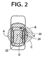
- the transmitter 22 is disposed in an almost central part of the operator's compartment, namely, adjacent to a center console, as indicated in Fig. 2.
- the other transmitter 24 is embedded in a door knob provided on the outer surface of the door 20 such that the transmitter 24 is exposed in the outer surface of the door knob.
- the receiver 26 is provided to receive identifier signals transmitted from a portable unit 32 (described below) in respective two different communication areas A and B (indicated in Fig. 2) within which the respective two transmitters 22, 24 are capable of communicating with the portable unit 32.
- the receiver 26 is positioned so that it is able to receive the identifier signals (described below) transmitted from either of the two areas A and B.
- the transmitter 22 and the receiver 26 constitute a communication device 27 for detecting the portable unit 32 within the first area A, while the transmitter 24 and the receiver 26 constitute a communication device 28 for detecting the portable unit 32 within the second area B.
- Each of the transmitters 22, 24 is adapted to transmit a request signal requesting the portable unit 32 to transmit an identifier signal, and the receiver 26 receives the identifier signal transmitted from the portable unit 32.
- the identifier checking portion 12 of the ECU 10 checks the identifier signal to determine whether an identifier represented by the identifier signal identifies the vehicle, namely, whether the identifier identifying the portable unit 32 matches an identifier of the vehicle. In the present embodiment, this determination is made by determining whether the identifier represented by the received identifier signal is the same as the identifier of the vehicle. Based on a result of the checking or determination by the identifier checking portion 12, the ECU 10 controls the driver circuit 13 to control the operating state of the door locking motor 18, more specifically, to hold the closed door 20 in the locked or unlocked state.
- the communication device 27 is capable of communicating with the portable unit 32 while the portable unit 32 is located within the first area A which covers the vehicle operator's or front compartment and a passenger's or rear compartment of the vehicle, and further covers areas near and external to the front right door 20 and the other three doors of the vehicle, as indicated in Fig. 2.
- the communication device 28 is capable of communicating with the portable unit 32 while the portable unit 32 is located within the second area B which covers the vehicle operator's seat and an area near and external to the front right door 20, as also indicated in Fig. 2.
- the first and second areas A and B are determined by the transmitting capacities of the transmitters 22, 24, respectively.
- the door-locking controller or ECU 10 and the communication devices 27, 28, which are mounted on the vehicle, are referred to as "vehicle-mounted devices".
- the transmitters 22, 24 are operated according to control signals received from the ECU 10, to transmit the request signals.
- An example of the arrangement of each transmitter 22, 24 is illustrated in Fig. 3.
- the illustrated transmitter includes a transistor 35, an oscillator element 36, and an antenna 38.
- an ON signal from the ECU 10 is received as the control signal by a terminal 39 of the transmitter 22, 24, the output signal of the transistor 35 is transmitted as the request signal through the antenna 38.
- This request signal has a predetermined frequency (134.2kHz in this specific example), which is determined by the oscillator element 36.
- an OFF signal from the ECU 10 is received by the terminal 39, no electric current is applied to the base of the transistor 35.
- the receiver 26 is adapted to receive the identifier signal transmitted from the portable unit 32, and provides the ECU 10 with an identifier represented by the identifier signal.
- An example of the arrangement of the receiver 26 is illustrated in Fig. 4.
- the illustrated receiver includes an antenna 40, a plurality of band-pass filters 41-43, a local oscillator 44, a mixer 46, a low-pass filter 48, a plurality of amplifiers 50, 51, and a comparator 52.
- the identifier signal receiver from the antenna 40 is filtered by the band-pass filters 41, 42 and amplified by the preamplifier 50, so that a signal having a predetermined frequency (300MHz in this specific example) is extracted.
- the extracted signal is mixed by the mixer 46 with a signal generated by the local oscillator 44, to provide a medium-frequency signal, which is then filtered by the band-pass filter 43 to remove an undesired frequency component.
- the medium-frequency signal is amplified by the limiter amplifier 51 and is then filtered by the low-pass filter 48 to remove an undesired high-frequency component.
- the thus obtained signal is compared by the comparator 52 with a reference signal to provide a digital signal indicative of a result of the comparison. This digital signal is applied to the ECU 10.
- a courtesy lamp switch 54 To the ECU 10, there are further connected a courtesy lamp switch 54, an ignition switch 56, an alarm indicator 58, and a seat-belt switch 59, which are provided within the operator's compartment.
- An output signal of the seat-belt switch 59 indicates whether a seat belt is used by the vehicle operator, while an output signal of the courtesy lamp switch 54 indicates whether the door 20 is in the open or closed position.
- the alarm indicator 58 is activated when the receiver 26 does not receive any identifier signal identifying the vehicle, as described below.
- the alarm indicator 58 is disposed within the interior of the vehicle. Where the alarm indicator 58 includes a buzzer, an operation of the buzzer can be heard by the vehicle operator even when the operator is outside the vehicle.
- the memory 16 includes a ROM, an EEPROM and a RAM.
- the ROM stores control programs illustrated in the flow charts of Figs. 6-8 and 10 and control patterns indicated in Fig. 9.
- the EEPROM stores data necessary to identify the vehicle in question, namely, data necessary to check whether the identifier signal received from the portable unit 32 identifies the vehicle or not.
- the RAM is used to store data indicative of a result of checking of the identifier signal (more precisely, the above-indicated digital signal received from the comparator 52) by the identifier checking portion 12.
- the portable unit 32 adapted to transmit the identifier signal also serves as an ignition key for turning on and off the ignition switch 56.
- the portable unit 32 is arranged to generate the identifier signal in response to the request signal received from the vehicle-mounted device 34 (transmitter 22 oar 24), or by manipulation of the portable unit 32.
- An example of the arrangement of the portable unit 32 is illustrated in Fig. 5.
- This portable unit 32 includes a receiver 62 with an antenna 60 for receiving the request signal from the transmitter 22, 24, a transmitter 66 with an antenna 64 for transmitting the identifier signal to the receiver 26, an identifier-signal generating portion 68 and a switch 70, a wave detector 72 and a comparator 74.
- the signal received by the antenna 60 of the receiver 62 is processed by the wave detector 72, amplified by an amplifier and compared by the comparator 74 with a reference signal.
- the received signal is the request signal having 134.2kHz transmitted from the transmitter 22, 24, a high-level signal is applied to the identifier-signal generating portion 68, so that the generating portion 68 generates the identifier signal.
- the frequency of the request signal transmitted from the transmitter 22, 24 is thus checked by the receiver 62, to assure that the portable unit 32 responds to only the request signal that is transmitted to the vehicle whose ignition switch 56 is operable by the portable unit 32.
- the switch 70 is a normally open switch, and is closed when it is operated by the vehicle operator (holder of the portable switch 32), so that a high-level signal is applied from a DC power source 78 to the identifier-signal generating portion 68, to generate the identifier signal.
- a digital control signal (“1" or "0"
- the output signal of the transistor 80 is transmitted as the identifier signal through the antenna 64.
- the frequency (300MHz) of this identifier signal is determined by an oscillator element 82, so that the identifier signal can be received by the receiver 26 of the vehicle-mounted device 34.
- the identifier signal transmitted from the transmitter 66 of the portable unit 32 identifies the vehicle. That is, an identifier represented by the identifier signal and identifying the portable unit 32 matches an identifier of the vehicle represented by data stored in the memory 16 of the ECU 10.
- the identifier checking portion 12 of the ECU 10 checks the received identifier signal to see whether the identifier signal is the one received from the portable unit 32, and is not the one received from a portable unit used for the other vehicles.
- the request signal is transmitted from one of the transmitters 22, 24 when a predetermined condition is satisfied.
- the identifier checking portion 12 determines whether the receiver 26 has received the identifier signal, and further determines whether the identifier represented by the received identifier signal identifies the vehicle, that is, matches the identifier of the vehicle stored in the EEPROM of the memory 16. Based on the result of determination as to whether the received identifier signal identifies the vehicle, the driver circuit 14 is controlled to control the door locking motor 18.
- the present embodiment is arranged such that a control signal is applied from the ECU 10 to the transmitter 24 to cause the transmitter 24 to transmit the request signal through the antenna 38, when the door 20 is opened while the ignition switch 56 is in the off state. That is, an opening action or movement of the door 20 after the ignition switch 56 is turned off is considered as a symptom indicating an intention of the vehicle operator of getting off the vehicle. Upon detection of this symptom, the request signal is transmitted from the transmitter 24.
- the identifier checking portion 12 checks if the received identifier signal is the one received from the portable unit 32 which is used to turn on and off the ignition switch 56 of the vehicle in question, namely, if the received identifier signal identifies the vehicle in question. If the received identifier signal identifies the vehicle, a signal indicative of this fact is stored in the RAM of the memory 16, and the transmitter 24 is commanded to terminate the intermittent transmission of the request signal. The transmitter 24 is commanded to intermittently transmit the request signal at a predetermined time interval, as long as no identifier signal is received by the receiver 26, or as long as the identifier represented by the received identifier signal is different from the identifier of the vehicle.
- the control signal is applied from the ECU 10 first to the transmitter 22 and then to the transmitter 24, to cause the transmitters 22, 24 to transmit the request signals. That is, a closing action or movement of the door 20 from the open position to the closed position indicates a high probability that the vehicle operator has got off or left the vehicle. Upon detection of the closing action, the transmitters 22, 24 are commanded to transmit the request signals.
- the ECU 10 determines whether the receiver 26 has received an identifier signal and whether the received identifier signal identifies the vehicle.
- the operating state of the door locking motor 18 is controlled on the basis of both a result of the determination when the door 20 is closed and a result of the determination when the door 20 is opened.
- control program formulated to detect the ignition key in the form of the portable unit 32 when the door 20 is opened.
- This control program may be considered to be a program to detect the portable unit 32 after detection of a symptom indicating that the vehicle operator has got off the vehicle.
- step S1 The control program of Fig. 6 is initiated with step S1 to determine whether the ignition switch 56 has been turned off. If an affirmative decision (YES) is obtained in step S1, the control flow goes to step S2 in which a flag F is reset to "0". Then, step S3 is implemented to determine whether the door 20 has been opened. This determination is made by determining whether the courtesy lamp switch 54 is on or not.
- step S4 an identifier request mode is established for the transmitter 24 which is capable of communicating with the portable unit 32 in the second area B. In this mode, the transmitter 24 is operated to intermittently transmit the request signal to the portable unit 32, as long as the door 20 is open.
- step S4 is followed by step S5 to determine whether the door 20 has been closed. If a negative decision (NO) is obtained in step S5, that is, if the door 20 is kept open, the control flow goes to step S6 in which the ECU 10 commands the transmitter 24 to transmit the request signal requesting the portable unit 32 to transmit the identifier signal.
- NO negative decision
- Step S7 is implemented the predetermined time after the moment of generation of the request signal from the transmitter 24 (vehicle-mounted device 34), so that the portable unit 32 transmits its identifier signal in response to the reception of the request signal and so that the receiver 26 receives the transmitted identifier signal.
- step S7 If an affirmative decision (YES) is obtained in step S7, the control flow goes to step S8 to determine whether the identifier represented by the identifier signal received by the receiver 26 matches the identifier of the vehicle stored in the memory 16, that is, whether the received identifier signal identifies the vehicle in question. If an affirmative decision (YES) is obtained in step S8, the control flow goes to step S9 to set the flag F to "1", and to step S10 to establish a standby mode. Thus, one cycle of execution of the control program of fig. 6 is terminated.
- step S11 determines whether a predetermined time has passed after the request signal has been transmitted to the transmitter 24.
- the control flow goes back to step S5 to determine whether the door 20 is still kept open.
- steps S6, S7, S8 and S11 are repeatedly implemented until the affirmative decision (YES) is obtained in both steps S7 and S8. Accordingly, the request signal is intermittently transmitted from the transmitter 24 at a time interval equal to the predetermined time used in step S11.
- step S5 When the door 20 is closed, an affirmative decision (YES) is obtained in step S5, and the control flow goes directly to step S10 to establish the standby mode, so that the execution of the control program of Fig. 6 is terminated.
- the flag F remains to be "0" if the received identifier signal does not identify the vehicle while the request signal is intermittently transmitted, namely, if the receiver 26 has not received the identifier signal from the portable unit 32 corresponding to the vehicle while the door 20 is kept open, that is, before the door 20 is closed.
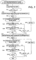
- a control program illustrated in the flow chart of Fig. 7 is executed.
- This control program is provided to detect the portable unit 32 when the door 20 is closed.
- the present control program is initiated with step S20 in which a flag IN and a flag OUT are both reset to "0".
- Step S20 is followed by step S21 to determine whether the door 20 has been closed. If an affirmative decision (YES) is obtained in step S1, the control flow goes to step S22 in which an identifier request mode is established for the transmitter 22 which is capable of communicating with the portable unit 32 in the first area A.
- the closing action of the door 20 indicates a high probability that the vehicle operator has got off or left the vehicle.
- step S22 and the subsequent steps are implemented upon closing of the door 20, to proceed with a further analysis as to whether the vehicle operator has actually got off the vehicle.
- the control program of Fig. 7 is considered to be a program for detecting the portable unit 32 after the detection of the operator's getting-off.
- Step S22 is followed by step S23 to reset a counter Rin to "0". Then, the control flow goes to step S24 in which the transmitter 22 is operated to transmit the request signal, and then to S25 to determine whether the receiver 26 has received an identifier signal. If an affirmative decision (YES) is obtained in step S25, step S26 is implemented to determine whether the identifier signal received by the receiver 26 identifies the vehicle. If an affirmative decision (YES) is obtained in step S27, the control flow goes to step S27 in which the flag IN is set to "1".
- step S28 determines whether the count counted by the counter Rin is equal to or larger than "3". If a negative decision (NO) is obtained in step S28, the control flow goes to step S29 to increment the counter Rin, and goes back to step S24.
- control program of Fig. 7 in the present embodiment is formulated to repeat steps S24-S26 three times for checking whether the receiver 26 has received the identifier signal from the portable unit 32, that is, the identifier signal which identifies the vehicle in question. If an affirmative decision (YES) is not obtained in step S26 within a predetermined time corresponding to the count "3" of the counter Rin, the flag IN remains to be "0", indicating that the portable unit 32 is not located in the first area A.
- step S30 in which the identifier request mode is established for the transmitter 22 capable of communicating with the second area B.
- step S30 is followed by step S31 to reset a counter Rout to "0".
- step S32 is implemented to command the transmitter 22 to transmit the request signal.
- steps S33-S37 similar to the steps S25-S29 described above.
- S33 and S34 are provided to determine whether the receiver 26 has received an identifier signal and whether the received identifier signal identifies the vehicle.
- step S35 If an affirmative decision (YES) is obtained in sep S34, the control flow goes to step S35 to set the flag OUT to "1". If a negative decision (N0) is obtained in step S33 or S34, the control flow goes to step S36 to determine whether the count counted by the counter Rout is equal to or larger than "3". If a negative decision (NO) is obtained in step S36, the control flow goes to step S37 to increment the counter Rout, and goes back to step S32. Steps S32-S34 are repeated three times to determine whether the portable unit 32 is located within the second area B. If the affirmative decision (YES) is not obtained in step S34 within the predetermined time, the flag OUT remains to be "0", indicating that the portable unit 32 is not located within the second area B.
- the driver circuit 14 for driving the door locking motor 28 is controlled on the basis of a result of the determination as to whether the portable unit 32 is detected in the second area B after the door 20 is opened, and results of the determinations as to whether the portable unit 32 is detected in the first area A and as to whether the portable unit 32 is detected in the second area B after the door 20 is closed.
- the present automatically operated and controlled door-locking system is controlled in one of three control modes which is selected according to a mode selecting program illustrated in the flow chart of Fig. 10.
- the control program of Fig. 10 is initiated with step S40 to determine whether the portable unit 32 is detected in the first area A while the door 20 is closed (after the door 20 has been closed), that is, whether the flag Rin is set at "1". If a negative decision (NO) is obtained in step S40, the control flow goes to step S41 to determine whether the portable unit 32 is detected in the second area B while the door 20 is closed, that is, whether the flag Rout is set at "1". If an affirmative decision (YES) is obtained in step S40, the control flow goes to step S42 to select an ENGINE START STANDBY mode.
- step S41 If an affirmative decision (YES) is obtained in step S41, the control flow goes to step S43 to establish a DOOR LOCKING STANDBY mode. If the negative decision (NO) is obtained in both of steps S40 and S41, the control flow goes to step S44 to determine whether the portable unit 32 is detected in the second area B while the door 20 is open, that is, whether the flag F is set at "1". If an affirmative decision (YES) is obtained in step S44, the control flow goes to step S43 to establish the DOOR LOCKING STANDBY mode. If a negative decision (NO) is obtained in step S44, the control flow goes to step S45 to establish an ALARMING AND DOOR LOCKING STANDBY mode.
- the three control modes indicated above will be discussed in detail by reference to the table of Fig. 9.
- the table of Fig. 9 indicates a relationship between the three control modes and five states (STATES 1-5) of the door-locking system.
- the ENGINE START STANDBY mode is selected in step S42 when the system is placed in STATE 1 wherein the portable unit 32 is detected in only the first area A while the door 20 is closed.
- the ECU 10 commands an electronic engine control device to establish the ENGINE START STANDBY mode in which an immobilizer is released to cancel the inhibition of ignition of an engine and fuel injection into the engine.
- the ENGINE START STANDBY mode is also established in step S42 when the door-locking system is placed in STATE 2 wherein the portable unit 32 is detected in both of the first and second areas A and B while the door 20 is closed.
- the portable unit 32 is located in an overlapping part D of the first and second areas A, B, as indicated in Fig. 2, so that there is a possibility that the vehicle operator starts the engine again.
- the DOOR LOCKING STANDBY mode is selected in step S43 when the door-locking system is placed in STATE 3 wherein the portable unit 32 is detected in only the second area B while the door 20 is closed.
- a control program for performing a door locking standby control is executed as explained below by reference to the flow chart of Fig. 8, such that the closed door 20 is automatically locked where a predetermined condition is satisfied.
- the vehicle operator is located in a part C of the second area B, which part C is outside the first area A. In view of this high possibility, it is desirable to lock the closed door 20.
- the DOOR LOCKING STANDBY mode is selected in step S43 also when the door-locking system is placed in STATE 4 wherein the portable unit 32 is detected in neither the first area A nor the second area B, namely, detected in an area E outside the first and second areas A, B, while the door 20 is closed, but is detected in the second area B while the door 20 is open.
- the DOOR LOCKING STANDBY mode is selected where the flag F has been set at "1" in step S9.
- the flag F set at "1" (stored in the RAM of the memory 16) indicates a symptom that the vehicle operator has an intention of getting off the vehicle.
- the ALARMING AND DOOR LOCKING STANDBY mode is selected in step S45 when the door-locking system is placed in STATE 5 wherein the portable unit 32 is neither detected in the second area B while the door 20 is open, nor detected in the first and second areas A, B while the door 20 is closed.
- the portable unit 32 is not detected in either the first area A or the second area while the door 20 is closed, and is not detected in the second area B while the door 20 is open, there is a possibility that the portable unit 32 is defective or its battery is exhausted, for instance.
- the alarm indicator 58 is activated to inform the vehicle operator of this possibility.
- the DOOR LOCKING STANDBY mode is established.
- the door locking control program is executed as illustrated in the flow chart of Fig. 8.
- This control program is formulated to lock the door 20 in the closed position when the vehicle operator is located outside the vehicle and when the portable unit 32 (which also serves as the ignition key in this embodiment) is not left within the vehicle.
- the door 20 is locked in at least one of the following two cases: (1) The portable unit 32 (vehicle operator) remains in the second area B for a sufficiently long time, and is not located in the first area A (not left in the interior of the vehicle); and (2) The portable unit 32 (vehicle operator) is kept undetected in the second area B (is presumably located in the area E) for a sufficiently long time while the portable unit 32 is not located in the first area A.
- step S50 to reset a counter n NG to "0".
- step S50 is followed by sep S51 to determine whether the count of the counter n NG is equal to or larger than a threshold value n s .
- step S51 is implemented for the first time, the count is zero, and a negative decision (NO) is obtained in step S51, so that step S52 is implemented to command the transmitter 24 to transmit the request signal.
- step S52 is followed by steps S53 and S54 to determine whether the receiver 26 has received an identifier signal and whether the received identifier signal identifies the vehicle in question.
- step S53 If a negative decision (NO) is obtained in step S53 or S54, the control flow goes to step S55 in which the counter n NG is incremented, and then goes back to step S51. Steps S51-S55 are repeatedly implemented until the predetermined time corresponding to the threshold value n s has passed. When the predetermined time has passed, and an affirmative decision (YES) is obtained step S51, the control flow goes to step S57.
- step S54 If an affirmative decision (YES) is obtained in step S54, the control flow goes to step S56 to determine whether a predetermined time T has passed after the receiver 26 has received the identifier signal which identifies the vehicle. Steps S52, S53, S54 and S56 are repeatedly implemented until an affirmative decision (YES) is obtained in step S56, that is, until the predetermined time T has passed. When the affirmative decision (YES) is obtained in step S56, the control flow goes to step S57.
- the predetermined time T is the sufficiently long time indicated above with respect to the case (1) in which the closed door 20 is locked since the portable unit 32 is held in the second area B for a long time. For instance, the predetermined time T is 30 seconds.
- step S57 the transmitter 22 is operated to transmit the request signal.
- step S57 is followed by step S58 to determine whether the receiver 26 has received an identifier signal, and step S59 to determine whether the received identifier signal identifies the vehicle. If a negative decision (NO) is obtained in sep S58 or S59, the control flow goes to step S60 in which the driver circuit 14 is controlled to activate4 the door locking motor 18 for locking the door 20 in the closed position. If an affirmative decision (YES) is obtained in step S59, the motor 18 is not operated so that the door 20 is held in the unlocked state.
- NO negative decision
- YES affirmative decision
- the door-locking system is arranged such that the DOOR LOCKING STANDBY mode is established when the portable unit 32 is detected in the area B after the door 20 has been opened, even if the portable unit 32 is not detected after the door 20 has been closed.
- the door 20 is locked when the predetermined condition is satisfied as described above by reference to the flow chart of Fig. 8.
- This arrangement permits locking of the door 20 even when the vehicle operator who has got off the vehicle quickly swings the door 20 back to the closed position, whereby the operating reliability of the system is improved.
- steps S52-S54 and S57-S59 are implemented to detect the position of the portable unit 32 when there is detected a high probability that the vehicle operator has an intention of getting off the vehicle.
- the door 20 is locked also when the system is placed in STATE 3 wherein the vehicle operator remains in the part C of the second area B for a long time.
- the door 20 is locked also when the system is placed in STATE 4 wherein the portable unit 32 is not detected after the door 20 has been closed.
- the determination as to whether the portable unit 32 is detected in the first area A and the determination as to whether the portable unit 32 is detected in the second area B are both effected, so that whether the door locking motor 18 is controlled based on the exact position of the portable unit 32.
- the reliability of the control of the door locking motor 18 is further improved owing to the detection of the portable unit 32 after the door 20 is opened and the detection of the same after the door 20 is closed.
- the alarm indicator 58 is activated if the portable unit 32 is neither detected while the door 20 is open, nor detected while the door 20 is closed. In this case, the vehicle operator is informed that the portable unit 32 is defective, or its battery is exhausted.
- the transmission of the request signal from the transmitter 24 is terminated when the identifier signal received by the receiver 26 identifies the vehicle, so that the consumption of the electric energy is reduced. Further, the transmitter 24 is adapted to intermittently transmit the request signal at the predetermined time interval, until the receiver 26 has received the identifier signal which identifies the vehicle. The intermittent transmission of the request signal requires a reduced amount of electric energy, than continuous transmission of the same.
- the present embodiment it is determined that there is a symptom that the vehicle operator has an intention of getting off the vehicle, where the door 20 is opened while the ignition switch 56 is off. Namely, it is not determined that there is the above-indicated symptom, where the ignition switch 56 is merely turned off or where the output signal of the seat-belt switch 59 indicates that the vehicle operator has released the seat belt.
- the present arrangement assures increased reliability in the determination that the vehicle operator has an intention of getting off the vehicle, and is effective to avoid unnecessary transmission of the request signal requesting the portable unit 32 to transmit the identifier signal, resulting in a reduced amount of consumption of electric energy by the door-locking system.
- the two communication devices 27, 28 cooperate to constitute a plurality of specific-area communication devices adapted to detect the portable unit 32 in the respective first and second areas A and B, and also constitute a communication device capable of communicating with the portable unit 32 in the different areas A, B.
- the communication device 28 serves as a first communication device operable upon detection of a symptom that the vehicle operator has an intention of getting off the vehicle
- the communication device 27 serves as a second communication device capable of communicating with the portable unit 32 in the first area A whose major part lies within the vehicle
- the communication deice28 serves as a third communication device capable of communicating with the portable unit 32 in the second area B whose major part is outside the vehicle.
- the communication devices 27, 28 cooperate to serve as a fourth communication device operable upon detection of a high probability that the vehicle operator has got off the vehicle.
- the battery 19, door locking motor 18 and driver circuit 14 cooperate to constitute a major portion of a power-operated locking device for locking the door 24, while the door-locking controller in the form of the ECU 10 serves as a locking-device controller for controlling the power-operated locking device.
- the power-operated locking device, the locking-device controller and the communication devices 27, 28 cooperate to constitute a major portion of the automatically operated and controlled door-locking system for the automotive vehicle, which may be considered to be a vehicle state control device for controlling the state of a vehicle.
- the transmitters 22, 24 which include the transistor 35 are adapted to intermittently transmit the request signal under the control of the ECU 10, which is adapted to implement steps S6, S7, S8 and S11.
- a portion of the ECU 10 assigned to implement steps S8 and S10 provides a request terminating portion for terminating the transmission of the request signal upon determination that the received identifier signal identifies the vehicle.
- the memory 16 of the ECU 10 serves as a data memory for storing data indicating the above-indicated determination after or upon detection of a symptom that the vehicle operator has an intention of getting off the vehicle.
- a portion of the ECU 10 assigned to implement steps S1 and S3 serves as a symptom detecting means for detecting a symptom that the vehicle operator has an intention of getting off the vehicle
- a portion of the ECU 10 assigned to implement step S21 serves as getting-off detecting means for detecting that the vehicle operator has got off the vehicle.
- a portion of the ECU 10 assigned to implement steps S20-S36 serves as a portable unit detecting device for detecting the position of the portable unit 32 when it is detected that the vehicle operator has got off the vehicle.
- This portable unit detecting device is capable of detecting the portable unit 32 in the different areas A and B.
- a portion of the ECU 10 assigned to detect STATE 4 (implement steps S40, S41, S43 and S44) and to control the driver circuit 14 serves as a control device for selecting a door locking standby mode when the receiver 26 has not received the identifier signal identifying the vehicle, after the detection of a symptom that the vehicle operator has an intention of getting off the vehicle.
- a portion of the ECU 10 assigned to implement steps S1-S11 of Fig. 6 serves as a portable unit detecting device for detecting the portable unit 32 after it is detected that the vehicle operator has an intention of getting off the vehicle.
- the relationship between the STATES 1-5 and the three control modes indicated in the table of Fig. 9 may be suitably modified.
- the illustrated embodiment is adapted to establish the ENGINE START STANDBY mode in STATE 2 wherein the portable unit 32 is detected in both of the first and second areas A, B, the DOOR LOCKING STANDBY mode may be selected in STATE 2.
- the overlapping part D of the first and second areas A, B includes a portion which is outside the vehicle.
- the door-locking system may be placed in TATE 2 when the portable unit 32 is located in the above-indicated portion of the overlapping part D.
- the portable unit 32 While the ALARMING AND DOOR LOCKING STANDBY mode is selected in STATE 5 in the illustrated embodiment, only the alarm indicator 58 may be activated in STATE 5.
- the portable unit 32 When the portable unit 32 is detected neither in the first area A nor in the second area B, the portable unit 32 may actually exist within the interior of the vehicle. In this case, it is desirable not to lock the door 20.
- the illustrated embodiment is arranged to control the door locking motor 18 on the basis of the results of the two determinations as to whether the portable unit 32 is detected while the door 20 is open and closed, respectively.
- the motor 18 may be controlled on the basis of the result of one of those two determinations. Described in detail, where the portable unit 32 is detected while the door 20 is open, the motor 18 is activated to lock the door 20 soon after the door 20 is closed. Alternatively, the door 20 may be locked a predetermined time after the door 20 is closed. Namely, the execution of the control program of Fig. 8 is not essential.
- the control program of Fig. 6 is adapted to detect the portable unit 32 in the second area B only while the door 20 is open, the control program may be modified to detect the portable unit 32 in the first and second areas A and B while the door 20 is open.
- the control program of Fig. 6 may be replaced by a control program illustrated in the flow chart of Fig. 11, in which the transmitter 24 intermittently transmits the request signal at the predetermined time interval even after the affirmative decision (YES) is obtained in step S8, as long as the door 20 is held open.
- step S10' is implemented, and the control program is terminated.
- step S21 of the control program of Fig. 7 is not necessary, because the control program of Fig. 7 is initiated when the door 20 is closed, that is, when the standby mode is establish in step S10'.
- the request signal is not continuously transmitted but is intermittently transmitted from the transmitter 24, so that the required electric energy consumption is reduced.
- the transmitter 24 is operated to transmit the request signal where the door 20 is opened while the ignition switch 56 is off.
- the ECU 10 determines that there is a symptom that the vehicle operator has an intention of getting off the vehicle.
- the ECU 10 may determine that there is a symptom that the vehicle operator has an intention of getting off the vehicle, when the ignition switch 56 is turned off, and/or when the output signal of the seat-belt switch 59 indicates that the vehicle operator has released the seat belt.
- the detection of the portable unit 32 in the second area B may be effected upon detection of the above-indicated symptom, according to a control program as illustrated in the flow chart of Fig. 12.
- the control program is initiated with step S101 to determine whether the ignition switch 56 is turned off and/or the output signal of the seat-belt switch 59 indicates the vehicle operator's releasing of the set belt. If an affirmative decision (YES) is obtained in step S101, it means that there is a symptom that the vehicle operator has an intention of getting off the vehicle. In this case, the control flow goes to step S102 to reset the flag F to "0", and step S103 in which the identifier request mode is established for the transmitter 24 capable of communicating with the portable unit 32 in the second area B.
- steps S104 and S105 are implemented to determine whether the door 20 is in the closed position, and determine whether the door 20 has been placed in the closed position within a predetermined short time after the door 20 was opened. If an affirmative decision (YES) is obtained in step S105, it means that there is a high probability that the vehicle operator has got off the vehicle. In this case, the control flow goes to step S110.
- step S104 If a negative decision (NO) is obtained in step S104, or if an affirmative decision (YES) is obtained in step S104 while a negative decision (NO) is obtained in step S105, it means that the door 20 is opened, or that the door 20 is kept closed after the ignition switch 56 is turned off and/or the vehicle operator has released the seat belt. In these cases, the control flow goes to step S106 in which the identifier request mode is established for the transmitter 22 capable of communicating with the portable unit 32 in the first area A. Then, steps S107-S111 are implemented as described above with respect to steps S7-S11 of Fig. 6.
- the identifier request mode is established even where the vehicle operator has released the seat belt while the ignition key 56 is held on.
- the releasing of the seat belt alone may be an indication that the vehicle operator has an intention of getting off the vehicle.
- the present embodiment permits locking of the door 20 where the vehicle operator has left the vehicle with the ignition switch 56 held on.
- the portable unit 32 should not serve as the ignition key used to turn on and off the ignition switch 56. That is, the portable unit 32 must be a member which is carried by the vehicle operator and which is not used as the ignition key.
- the request signal is transmitted even before the door 20 is opened, that is, even while the door 20 is held closed with the negative decision (NO) being obtained in step S105.
- the portable unit 32 also serves as the ignition key.
- the first and second embodiments may be modified such that the portable unit 32 does not serve as the ignition key and is exclusively used as a member for detecting the position of the vehicle operator.
- transmitters 22, 24, receiver 26 and portable unit 32 are constructed as shown in Figs. 3-5, respectively, for illustrative purpose only, those elements may be otherwise constructed.
- Automatically controlled door-locking system for locking at least an operator's door (20) of a vehicle, including a power-operated device (14, 18, 19) for selectively locking and unlocking at least the vehicle operator's door, a symptom detecting device (10, 54, 56, 59 for detecting a symptom indicating that the vehicle operator has an intention of getting off the vehicle, a communication device (27, 28) having a signal-receiving device (10, 26) and an identifier-signal requesting device (10, 24) operable upon detection of the above-indicated symptom, to transmit to a portable unit (32) a request signal requesting the portable unit to transmit back to the signal-receiving device (10, 26) an identifier signal identifying the portable unit, and a locking-device controller (10) operable when the identifier signal received
Landscapes
- Engineering & Computer Science (AREA)
- Computer Networks & Wireless Communication (AREA)
- Physics & Mathematics (AREA)
- General Physics & Mathematics (AREA)
- Mechanical Engineering (AREA)
- Lock And Its Accessories (AREA)
- Selective Calling Equipment (AREA)
Applications Claiming Priority (4)
| Application Number | Priority Date | Filing Date | Title |
|---|---|---|---|
| JP24135799 | 1999-08-27 | ||
| JP24135799 | 1999-08-27 | ||
| JP2000141404 | 2000-05-15 | ||
| JP2000141404A JP4649703B2 (ja) | 1999-08-27 | 2000-05-15 | 移動体自動施錠装置 |
Publications (2)
| Publication Number | Publication Date |
|---|---|
| EP1079053A2 true EP1079053A2 (fr) | 2001-02-28 |
| EP1079053A3 EP1079053A3 (fr) | 2004-01-07 |
Family
ID=26535215
Family Applications (1)
| Application Number | Title | Priority Date | Filing Date |
|---|---|---|---|
| EP20000117532 Withdrawn EP1079053A3 (fr) | 1999-08-27 | 2000-08-14 | Système de verrouillage automatique d'une porte d'un véhicule utilisant une unité portative de transmission de signal d'un identifiant |
Country Status (3)
| Country | Link |
|---|---|
| US (1) | US6476517B1 (fr) |
| EP (1) | EP1079053A3 (fr) |
| JP (1) | JP4649703B2 (fr) |
Cited By (7)
| Publication number | Priority date | Publication date | Assignee | Title |
|---|---|---|---|---|
| EP1336938A3 (fr) * | 2002-02-15 | 2004-04-14 | Alps Electric Co., Ltd. | Dispositif monté sur véhicule avec unité de commande de communication |
| EP1394751A3 (fr) * | 2002-09-02 | 2004-04-28 | Calsonic Kansei Corporation | Système de communication sans fils pour véhicule |
| GB2396184A (en) * | 2002-10-09 | 2004-06-16 | Honda Motor Co Ltd | Radio type vehicle door locking/unlocking device |
| EP1493132A1 (fr) * | 2002-03-08 | 2005-01-05 | Valeo Securite Habitacle | Procede de scrutation de badges identifiant pour vehicule automobile |
| DE102005005864A1 (de) * | 2005-02-09 | 2006-08-17 | Conti Temic Microelectronic Gmbh | Verfahren zum Betrieb eines Schließsystems für ein Kraftfahrzeug |
| US20180075672A1 (en) | 2016-08-12 | 2018-03-15 | Snap-On Incorporated | Method and system for providing diagnostic filter lists |
| US10269191B2 (en) | 2016-08-12 | 2019-04-23 | Snap-On Incorporated | Method and system for displaying PIDs based on a PID filter list |
Families Citing this family (37)
| Publication number | Priority date | Publication date | Assignee | Title |
|---|---|---|---|---|
| ES2254484T3 (es) * | 2000-09-08 | 2006-06-16 | Peugeot Citroen Automobiles Sa | Procedimiento y dispositivo de bloqueo automatico de un vehiculo automovil. |
| JP4636735B2 (ja) * | 2001-06-06 | 2011-02-23 | 富士通テン株式会社 | キーレスエントリ装置 |
| US6784803B1 (en) * | 2001-08-23 | 2004-08-31 | Seatbelt Safety First--Llc | Apparatus and methods for monitoring and detecting seat belt usage |
| JP3913661B2 (ja) * | 2002-10-09 | 2007-05-09 | 本田技研工業株式会社 | 車両用自動ドアロック施解錠装置 |
| JP4200799B2 (ja) * | 2003-04-02 | 2008-12-24 | 株式会社デンソー | 車載機器遠隔操作システム |
| JP4443866B2 (ja) * | 2003-06-30 | 2010-03-31 | シャープ株式会社 | 通知装置 |
| JP4349040B2 (ja) * | 2003-08-21 | 2009-10-21 | 三菱自動車工業株式会社 | 車両のドア解錠制御装置 |
| JP2005076369A (ja) * | 2003-09-02 | 2005-03-24 | Honda Motor Co Ltd | 車両用遠隔ドアロック制御装置 |
| JP4627991B2 (ja) * | 2004-01-05 | 2011-02-09 | 朝日電装株式会社 | シリンダ錠の保護装置 |
| JP4534921B2 (ja) * | 2005-09-13 | 2010-09-01 | 株式会社デンソー | 車載機器制御システム、車両側ユニット及び携帯機 |
| JP4561612B2 (ja) * | 2005-11-25 | 2010-10-13 | 株式会社デンソー | 車両ドア制御システム |
| JP4908868B2 (ja) * | 2006-02-16 | 2012-04-04 | 本田技研工業株式会社 | 車両用遠隔制御装置及びその方法 |
| US20070216517A1 (en) * | 2006-03-14 | 2007-09-20 | Denso International America, Inc. | Automatic vehicle door locking with seat occupant sensor |
| JP4754439B2 (ja) * | 2006-08-25 | 2011-08-24 | 本田技研工業株式会社 | 車両用電子キーシステム |
| DE102006042944B4 (de) * | 2006-09-13 | 2008-07-24 | Siemens Ag | Verfahren zum Verriegeln eines Fahrzeugs |
| US7683764B2 (en) * | 2007-03-22 | 2010-03-23 | Denso International America, Inc. | Automatic locking failsafe for vehicles with passive keys |
| US8091280B2 (en) * | 2007-06-01 | 2012-01-10 | GM Global Technology Operations LLC | Arms full vehicle closure activation apparatus and method |
| DE102009017404A1 (de) * | 2008-04-29 | 2009-11-05 | Volkswagen Ag | Verfahren und Vorrichtung zur Betätigung einer Tür oder Klappe eines Fahrzeugs |
| DE102008054526A1 (de) * | 2008-12-11 | 2010-06-17 | Huf Hülsbeck & Fürst Gmbh & Co. Kg | Türgriffanordnung für ein Kraftfahrzeug |
| JP5313701B2 (ja) * | 2009-01-13 | 2013-10-09 | アイシン精機株式会社 | 車両用ドアハンドル及びロッキングシステム |
| JP5169868B2 (ja) * | 2009-01-23 | 2013-03-27 | 株式会社デンソー | 車載機器制御システム |
| JP4840464B2 (ja) * | 2009-03-10 | 2011-12-21 | トヨタ自動車株式会社 | 車両用の電源制御装置 |
| JP5035367B2 (ja) | 2010-03-04 | 2012-09-26 | 株式会社デンソー | 車両用オートロックシステム |
| JP5472160B2 (ja) * | 2011-03-02 | 2014-04-16 | 株式会社デンソー | キーレスエントリシステム |
| KR101362325B1 (ko) * | 2012-07-19 | 2014-02-13 | 현대모비스 주식회사 | 트렁크 자동 열림 제어 장치 및 방법 |
| MX342365B (es) * | 2012-08-16 | 2016-09-27 | Schlage Lock Co Llc | Sistema de lector inalámbrico. |
| WO2014041955A1 (fr) * | 2012-09-12 | 2014-03-20 | 日産自動車株式会社 | Dispositif de commande pour élément d'ouverture/de fermeture de véhicule |
| DE102012025366A1 (de) * | 2012-12-28 | 2014-07-03 | Volkswagen Aktiengesellschaft | Schließvorrichtung für ein Fahrzeug und Verfahren zum Betreiben einer Schließvorrichtung |
| DE102013006128B4 (de) * | 2013-04-10 | 2021-01-14 | Audi Ag | Verfahren zum Betrieb eines Kraftfahrzeuges bei Verriegelung und Kraftfahrzeug |
| DE102013015119A1 (de) * | 2013-09-12 | 2015-03-12 | Brose Fahrzeugteile Gmbh & Co. Kommanditgesellschaft, Hallstadt | Stellvorrichtung zur Verstellung eines zwischen einer Schließstellung und einer Offenstellung verstellbaren Fahrzeugteils |
| US9633496B2 (en) * | 2014-01-09 | 2017-04-25 | Ford Global Technologies, Llc | Vehicle contents inventory system |
| US9836717B2 (en) | 2014-01-09 | 2017-12-05 | Ford Global Technologies, Llc | Inventory tracking system classification strategy |
| US10062227B2 (en) | 2014-01-09 | 2018-08-28 | Ford Global Technologies, Llc | Contents inventory tracking system and protocol |
| CN104775693B (zh) * | 2015-04-23 | 2016-11-23 | 邯郸学院 | 由计算机控制的门板锁定装置 |
| US11500395B2 (en) * | 2016-04-11 | 2022-11-15 | Telefonaktiebolaget Lm Ericsson (Publ) | Flight path control based on cell broadcast messages |
| JP6812939B2 (ja) * | 2017-09-27 | 2021-01-13 | トヨタ自動車株式会社 | 端末、車両制御システム、及び車両制御方法 |
| JP2022168790A (ja) * | 2021-04-26 | 2022-11-08 | トヨタ自動車株式会社 | 車両制御装置、車両制御方法、車両制御プログラム、車両制御システム、及び通信端末 |
Citations (1)
| Publication number | Priority date | Publication date | Assignee | Title |
|---|---|---|---|---|
| JPS6237479A (ja) | 1985-08-12 | 1987-02-18 | 日産自動車株式会社 | 無線式施解錠制御装置 |
Family Cites Families (12)
| Publication number | Priority date | Publication date | Assignee | Title |
|---|---|---|---|---|
| JPS60119875A (ja) * | 1983-11-29 | 1985-06-27 | 日産自動車株式会社 | 車両用施錠制御装置 |
| DE4123654A1 (de) * | 1991-07-17 | 1993-01-21 | Bayerische Motoren Werke Ag | Verfahren zum erkennen eines im fahrzeuginnern eingeschlossenen tragbaren transponders |
| FR2697864B1 (fr) * | 1992-11-06 | 1995-01-06 | Valeo Electronique | Système pour commander à distance le verrouillage et le déverrouillage des portes et des ouvrants d'un habitacle, notamment d'un véhicule automobile. |
| US5600302A (en) * | 1994-04-19 | 1997-02-04 | Lewis; James | Vehicle-based anti-lockout system |
| US5973611A (en) * | 1995-03-27 | 1999-10-26 | Ut Automotive Dearborn, Inc. | Hands-free remote entry system |
| FR2740501B1 (fr) * | 1995-10-26 | 1998-06-19 | Valeo Securite Habitacle | Systeme mains libres de deverrouillage et/ou d'ouverture d'ouvrant de vehicule automobile |
| JPH09132114A (ja) * | 1995-11-06 | 1997-05-20 | Tokai Rika Co Ltd | 車両盗難防止装置 |
| FR2749607B1 (fr) * | 1996-06-10 | 1998-07-24 | Valeo Electronique | Procede de deverrouillage des portieres et/ou de desactivation d'un dispositif electronique d'immobilisation pour vehicule automobile, et dispositif pour sa mise en oeuvre |
| FR2754090B1 (fr) * | 1996-09-27 | 1998-12-18 | Valeo Electronique | Perfectionnements aux telecommandes rf a double portee pour vehicule automobile |
| JP3287277B2 (ja) | 1997-09-18 | 2002-06-04 | トヨタ自動車株式会社 | 車両用施錠制御装置 |
| DE19833451C1 (de) * | 1998-07-24 | 1999-08-19 | Siemens Ag | Diebstahlschutzsystem für ein Kraftfahrzeug |
| DE19846803C1 (de) * | 1998-10-10 | 2000-09-07 | Daimler Chrysler Ag | Verfahren zur Herstellung der Zugangsberechtigung zu einem motorangetriebenen Fahrzeug |
-
2000
- 2000-05-15 JP JP2000141404A patent/JP4649703B2/ja not_active Expired - Fee Related
- 2000-07-31 US US09/629,821 patent/US6476517B1/en not_active Expired - Lifetime
- 2000-08-14 EP EP20000117532 patent/EP1079053A3/fr not_active Withdrawn
Patent Citations (1)
| Publication number | Priority date | Publication date | Assignee | Title |
|---|---|---|---|---|
| JPS6237479A (ja) | 1985-08-12 | 1987-02-18 | 日産自動車株式会社 | 無線式施解錠制御装置 |
Cited By (20)
| Publication number | Priority date | Publication date | Assignee | Title |
|---|---|---|---|---|
| EP1336938A3 (fr) * | 2002-02-15 | 2004-04-14 | Alps Electric Co., Ltd. | Dispositif monté sur véhicule avec unité de commande de communication |
| EP1493132A1 (fr) * | 2002-03-08 | 2005-01-05 | Valeo Securite Habitacle | Procede de scrutation de badges identifiant pour vehicule automobile |
| EP1394751A3 (fr) * | 2002-09-02 | 2004-04-28 | Calsonic Kansei Corporation | Système de communication sans fils pour véhicule |
| US6944528B2 (en) | 2002-09-02 | 2005-09-13 | Calsonic Kansei Corporation | Wireless communication system for vehicle |
| GB2396184A (en) * | 2002-10-09 | 2004-06-16 | Honda Motor Co Ltd | Radio type vehicle door locking/unlocking device |
| GB2396184B (en) * | 2002-10-09 | 2005-02-16 | Honda Motor Co Ltd | Radio type locking/unlocking device |
| US7336151B2 (en) | 2002-10-09 | 2008-02-26 | Honda Motor Co., Ltd. | Radio type locking/unlocking device |
| DE102005005864A1 (de) * | 2005-02-09 | 2006-08-17 | Conti Temic Microelectronic Gmbh | Verfahren zum Betrieb eines Schließsystems für ein Kraftfahrzeug |
| US10269191B2 (en) | 2016-08-12 | 2019-04-23 | Snap-On Incorporated | Method and system for displaying PIDs based on a PID filter list |
| US9934624B2 (en) * | 2016-08-12 | 2018-04-03 | Snap-On Incorporated | Method and system for providing diagnostic filter lists |
| US20180075672A1 (en) | 2016-08-12 | 2018-03-15 | Snap-On Incorporated | Method and system for providing diagnostic filter lists |
| US10692307B2 (en) | 2016-08-12 | 2020-06-23 | Snap-On Incorporated | Method and system for providing diagnostic filter lists |
| US10692306B2 (en) | 2016-08-12 | 2020-06-23 | Snap-On Incorporated | Method and system for providing diagnostic filter lists |
| US10769870B2 (en) | 2016-08-12 | 2020-09-08 | Snap-On Incorporated | Method and system for displaying PIDs based on a PID filter list |
| US11403893B2 (en) | 2016-08-12 | 2022-08-02 | Snap-On Incorporated | Method and system for providing diagnostic filter lists |
| US11403895B2 (en) | 2016-08-12 | 2022-08-02 | Snap-On Incorporated | Method and system for providing diagnostic filter lists |
| US11694491B2 (en) | 2016-08-12 | 2023-07-04 | Snap-On Incorporated | Method and system for providing diagnostic filter lists |
| US11887413B2 (en) | 2016-08-12 | 2024-01-30 | Snap-On Incorporated | Method and system for displaying PIDs based on a PID filter list |
| US12106615B2 (en) | 2016-08-12 | 2024-10-01 | Snap-On Incorporated | Method and system for providing diagnostic filter lists |
| US12175814B2 (en) | 2016-08-12 | 2024-12-24 | Snap-On Incorporated | Method and system for displaying PIDs based on a PID filter list |
Also Published As
| Publication number | Publication date |
|---|---|
| EP1079053A3 (fr) | 2004-01-07 |
| US6476517B1 (en) | 2002-11-05 |
| JP4649703B2 (ja) | 2011-03-16 |
| JP2001140517A (ja) | 2001-05-22 |
Similar Documents
| Publication | Publication Date | Title |
|---|---|---|
| US6476517B1 (en) | Vehicle automatic door-locking system using identifier signal transmitting portable unit | |
| US7181189B2 (en) | Vehicular remote control system and tire pressure monitoring system | |
| KR100776109B1 (ko) | 자동 도어 제어 시스템 및 방법 | |
| US6522027B1 (en) | “Hands-free” access and/or engine starting system for automobile vehicles | |
| US6906612B2 (en) | System and method for vehicle passive entry having inside/outside detection | |
| US5293160A (en) | Keyless vehicle lock system with distance measuring | |
| US6552649B1 (en) | Vehicle control system | |
| KR100766189B1 (ko) | 차량 도어 제어 시스템 및 방법 | |
| US5912631A (en) | Mischief preventive automatic door locking apparatus and method for use with keyless entry system in automotive vehicle | |
| US6624741B1 (en) | Vehicle locking system | |
| US20060176147A1 (en) | Vehicle security system | |
| US10760322B2 (en) | Vehicle door opening/closing device and detection unit | |
| US20090058597A1 (en) | Vehicle communication system | |
| US6876292B2 (en) | Electronic key system for vehicle | |
| JP2004508474A (ja) | 自動車を施錠するための方法及び装置 | |
| US6538559B1 (en) | Remote control apparatus and remote control method | |
| JP2004027490A (ja) | 車両用遠隔制御システム及び車両遠隔制御システム用携帯機 | |
| US7009491B2 (en) | Dual purpose vehicle key fob for training tire pressure sensors | |
| US9126564B2 (en) | Communication apparatus for vehicle | |
| JP2002129794A (ja) | 遠隔操作用車載装置 | |
| JP4095295B2 (ja) | 車両用施解錠制御装置及び車両用施解錠制御システム | |
| JPH1193485A (ja) | 車両用遠隔操作制御装置およびそのシステム | |
| CN118269889A (zh) | 车载智能钥匙进入系统安全锁车控制方法、系统及车辆 | |
| CN118449242A (zh) | 车载无线充电设备的控制方法、控制装置、车辆和介质 | |
| JP2005273338A (ja) | 車両の無線式自動暗号照合施解錠装置 |
Legal Events
| Date | Code | Title | Description |
|---|---|---|---|
| PUAI | Public reference made under article 153(3) epc to a published international application that has entered the european phase |
Free format text: ORIGINAL CODE: 0009012 |
|
| 17P | Request for examination filed |
Effective date: 20000814 |
|
| AK | Designated contracting states |
Kind code of ref document: A2 Designated state(s): AT BE CH CY DE DK ES FI FR GB GR IE IT LI LU MC NL PT SE |
|
| AX | Request for extension of the european patent |
Free format text: AL;LT;LV;MK;RO;SI |
|
| PUAL | Search report despatched |
Free format text: ORIGINAL CODE: 0009013 |
|
| RIC1 | Information provided on ipc code assigned before grant |
Ipc: 7E 05B 49/00 A Ipc: 7G 07C 9/00 B |
|
| AK | Designated contracting states |
Kind code of ref document: A3 Designated state(s): AT BE CH CY DE DK ES FI FR GB GR IE IT LI LU MC NL PT SE |
|
| AX | Request for extension of the european patent |
Extension state: AL LT LV MK RO SI |
|
| AKX | Designation fees paid |
Designated state(s): DE FR GB IT |
|
| 17Q | First examination report despatched |
Effective date: 20040928 |
|
| RAP1 | Party data changed (applicant data changed or rights of an application transferred) |
Owner name: TOYOTA JIDOSHA KABUSHIKI KAISHA |
|
| STAA | Information on the status of an ep patent application or granted ep patent |
Free format text: STATUS: THE APPLICATION IS DEEMED TO BE WITHDRAWN |
|
| 18D | Application deemed to be withdrawn |
Effective date: 20170905 |
|
| RIC1 | Information provided on ipc code assigned before grant |
Ipc: E05B 49/00 20060101AFI20010109BHEP Ipc: G07C 9/00 20060101ALI20031113BHEP |