EP1079163A2 - Joint de dilatation flexible pour tuyauterie et sa méthode d'assemblage - Google Patents
Joint de dilatation flexible pour tuyauterie et sa méthode d'assemblage Download PDFInfo
- Publication number
- EP1079163A2 EP1079163A2 EP00105053A EP00105053A EP1079163A2 EP 1079163 A2 EP1079163 A2 EP 1079163A2 EP 00105053 A EP00105053 A EP 00105053A EP 00105053 A EP00105053 A EP 00105053A EP 1079163 A2 EP1079163 A2 EP 1079163A2
- Authority
- EP
- European Patent Office
- Prior art keywords
- cylindrical body
- peripheral surface
- tube joint
- ring
- flexible tube
- Prior art date
- Legal status (The legal status is an assumption and is not a legal conclusion. Google has not performed a legal analysis and makes no representation as to the accuracy of the status listed.)
- Granted
Links
Images




Classifications
-
- F—MECHANICAL ENGINEERING; LIGHTING; HEATING; WEAPONS; BLASTING
- F16—ENGINEERING ELEMENTS AND UNITS; GENERAL MEASURES FOR PRODUCING AND MAINTAINING EFFECTIVE FUNCTIONING OF MACHINES OR INSTALLATIONS; THERMAL INSULATION IN GENERAL
- F16L—PIPES; JOINTS OR FITTINGS FOR PIPES; SUPPORTS FOR PIPES, CABLES OR PROTECTIVE TUBING; MEANS FOR THERMAL INSULATION IN GENERAL
- F16L27/00—Adjustable joints; Joints allowing movement
- F16L27/02—Universal joints, i.e. with mechanical connection allowing angular movement or adjustment of the axes of the parts in any direction
- F16L27/026—Universal and axially displaceable joints
-
- F—MECHANICAL ENGINEERING; LIGHTING; HEATING; WEAPONS; BLASTING
- F16—ENGINEERING ELEMENTS AND UNITS; GENERAL MEASURES FOR PRODUCING AND MAINTAINING EFFECTIVE FUNCTIONING OF MACHINES OR INSTALLATIONS; THERMAL INSULATION IN GENERAL
- F16L—PIPES; JOINTS OR FITTINGS FOR PIPES; SUPPORTS FOR PIPES, CABLES OR PROTECTIVE TUBING; MEANS FOR THERMAL INSULATION IN GENERAL
- F16L27/00—Adjustable joints; Joints allowing movement
- F16L27/02—Universal joints, i.e. with mechanical connection allowing angular movement or adjustment of the axes of the parts in any direction
- F16L27/04—Universal joints, i.e. with mechanical connection allowing angular movement or adjustment of the axes of the parts in any direction with partly-spherical engaging surfaces
Definitions
- the present invention relates to an expansion flexible tube joint and an assembling method thereof, and more particularly, to an expansion flexible tube joint which can be handled easily and is used for connecting water pipes, and because of its expanding flexibility, even when excessive external force is applied, the external force can be absorbed to prevent the tubes from being destroyed, and to an assembling method thereof.
- a tube joint having a structure in which the tube joint itself can expand and contract is developed so as to absorb the external force to prevent the destruction.
- this tube joint since this tube joint only move to expand and contract, the movable range is of two-dimensional, and this structure is not sufficient to cope with external force due to ground subsidence or earthquake.
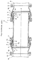
- this expansion flexible tube joint A comprises a first cylindrical body 1, a second cylindrical body 2 and a third cylindrical body 3, and is connected to body tubes B at opposite flanges 6 through bolts 10 and nuts 11.
- the first cylindrical body 1 comprises a pair of spherical surface ring members 1, 1 made of cast iron and formed with partially spherical outer peripheral surface 4.
- the second cylindrical body 2 comprises a sleeve 2 made of cast iron and inserted into the first cylindrical body 1 for relative movement from an axis direction of the cylindrical body.
- the third cylindrical body 3 comprises a pair of casing tubes 3, 3 made of cast iron.
- the third cylindrical body 3 has an inner peripheral surface 5 for fitting over each of outer peripheral surfaces 4 of the first cylindrical body 1, and is formed at its opposite ends with flanges which are connecting portions. Because the expansion flexible tube joint A is formed in this manner, the sleeve 2, the spherical surface ring materials 1, 1 and two casing tubes 3, 3 are connected to one another such that they can extend and contract and move relative to one another.
- An end portion 3a of each of the casing tubes 3 is covered with a protective rubber cover 7, thereby preventing earth, sand, dust and the like from entering into sliding portions.
- annular peripheral groove 1a is formed in an inner peripheral surface of the spherical surface ring material 1.
- An inner side of the annular peripheral groove 1a abuts against a C-shaped stainless steel lock-ring 17 having an angled cross section which is fitted and fixed to a recess formed in an outer peripheral surface of the sleeve 2 in the vicinity of its end.
- the present inventor researched and make every endeavor to develop the expansion flexible tube joint over the years and as a result, they improved the conventional expansion flexible tube joint, and completed an expansion flexible tube joint which has greater extending and retracting flexibility, the size can be reduced, and which is strong against external force.
- An expansion flexible tube joint of the present invention comprises a first cylindrical body having a pair of spherical surface ring materials each formed with partially spherical outer surface, a second cylindrical body comprising a sleeve inserted into the first cylindrical body for relative movement thereof from an axial direction thereof, the sleeve provided at its end portion with stopper means for limiting extending and contracting movement relative to the first cylindrical body, and third cylindrical bodies fitted over both outer peripheral surfaces and comprising a pair of casing tubes each having slidable spherical inner peripheral surfaces and connection portions at opposite ends thereof, wherein an end inner peripheral surface of each of the third cylindrical bodies at the side thereof to which the second cylindrical body is inserted is chamfered, and the chamfered angle is 16° or greater, and the stopper means is mounted to an outer peripheral surface of the second cylindrical body and is formed into a closed ring shape.
- the bending angle of the second cylindrical body can be increased as compared with the conventional tube joint, the overall length of the tube joint can be shortened accordingly, the size can be reduced, the producing cost is reduced, the weight is also reduced so that the assembling operation is facilitated. Further, even if great external force is applied, since stopper means is strengthened such that the stopper means have high resistance force, the stopper means does not come out from the second cylindrical body easily. Therefore, even if great external force such as earthquake is suddenly applied, the expanding and contracting flexibility of the tube joint can be maintained strongly.
- the chamfered angle is 16 to 20°, and the chamfered angle is set smaller as an inner diameter of the second cylindrical body is greater.
- a packing is inserted into between sliding surfaces of the first and third cylindrical bodies to enhance the watertightness, but according to the above structure, if the bending angle of the second cylindrical body is increased, it is possible to reduce the possibility that the packing inserted into between sliding surfaces of the first and third cylindrical bodies comes out with the rotational movement of the second cylindrical body. If the chamfered angle exceeds 20°, there is a possibility that the packing may come out as the second cylindrical body rotates, which is not preferable.
- the stopper means is formed into a closed ring shape by connecting a connection jig to a C-ring by fixing means.
- the stopper means can not easily come out from the second cylindrical body so that the entire tube joint can be strengthened, which is convenient.
- the stopper means is formed into a closed ring shape by welding a C-ring.
- the stopper means can not easily come out from the second cylindrical body so that the entire tube joint can be strengthened, which is convenient. Further, since the efficiency of the welding operation is high, there is a merit that the operation is facilitated.
- an assembling method of the invention of an expansion flexible tube joint comprising first and second cylindrical bodies slidably fitted to each other in an axial direction thereof, and the sliding movement range of the first and second cylindrical bodies in the axial direction being limited by a groove peripheral surface of an annular peripheral groove formed in an inner peripheral surface of the first cylindrical body and stopper means mounted and fixed to an outer peripheral surface of the second cylindrical body
- the assembling method comprises steps of: forming a notched portion in the inner peripheral surface of the first cylindrical body for bringing the annular peripheral groove and an outer peripheral surface of the first cylindrical body, and inserting the C-ring shaped stopper member which is cut at one portion in its peripheral direction and can be deformed in its diametrical direction into the annular peripheral groove which is formed deeper than a thickness of the stopper member in its diametrical direction; inserting the second cylindrical body into the first cylindrical body to which the stopper member is inserted; relatively moving the stopper member in the axial direction along the outer peripheral surface of the second cylindrical body which is inserted into the first cylindrical body while resilient
- the connecting step of the cut portion of the stopper member is carried out by screwing through a plate member.
- connection operation since the connection operation is easy, it is convenient when the operation is carried out in the field.
- the connecting step of the cut portion of the stopper member is carried out by welding.
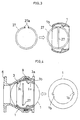
- FIG. 1 is a partial front sectional view of an expansion flexible tube joint of the invention.
- members having the same functions as those shown in FIG. 10 are designated by the same reference symbols. Since the expansion flexible tube joint of the present embodiment is laterally symmetrical, only one of the sides is shown in FIG. 1.
- This expansion flexible tube joint A comprises a first cylindrical body 1, a second cylindrical body 2 and a third cylindrical body 3, and is connected to flanges 6 provided on opposite ends of a body tube (not shown) by bolts (not shown) and nuts (not shown).
- the first cylindrical body 1 comprises a spherical surface ring member 1 made of cast iron and formed with partially spherical outer peripheral surface 4.
- the second cylindrical body 2 comprises a sleeve 2 made of cast iron and inserted into the first cylindrical body 1 for relative movement from an axis direction of the cylindrical body.
- the third cylindrical body 3 comprises a casing tube 3 made of cast iron.
- the third cylindrical body 3 has an inner peripheral surface 5 for fitting over each of outer peripheral surfaces 4 of the first cylindrical body 1, and is formed at its opposite ends with flanges 6 which are connecting portions.
- the flanges 6 may not necessarily be formed at the opposite ends of the casing tube 3, and the casing tube 3 is formed into a merely tube in some cases. Because the expansion flexible tube joint A is formed in this manner, the sleeve 2, the spherical surface ring material 1, and the casing tube 3 are connected to one another such that they can extend and contract and swing relative to one another.
- An end portion 3a of the casing tube 3 is covered with a protective rubber cover (not shown).
- annular peripheral groove 1 a is formed in an inner peripheral surface of the spherical surface ring material 1.
- An inner side of the annular peripheral groove 1a abuts against a stainless steel lock-ring 27 as stopper means having an angled cross section which is fitted and fixed to a recess formed in an outer peripheral surface of the sleeve 2 in the vicinity of its end.
- a stainless steel lock-ring 27 as stopper means having an angled cross section which is fitted and fixed to a recess formed in an outer peripheral surface of the sleeve 2 in the vicinity of its end.
- An inner peripheral surface of the end portion 3a of the casing tube 3 is chamfered, and the chamfer angle ⁇ is 18° with respect to a horizontal plane.
- the relation between the nominal size of the sleeve and the chamfer angle is set such that the chamfer angle is reduced as the nominal size is greater. This is because that if the rotation angle of the sleeve 2 is increased as the sleeve rotates, the spherical surface ring 1 is prone to come out and thus, it is preferable that the chamfer angle is increased within a range that the spherical surface ring 1 does not come out.
- the lock-ring 27 will be explained. As shown in FIG. 2(a), the lock-ring 27 is formed with screw holes 27b at left and right opposite sides in the vicinity of a cut portion K of the lock-ring, and holes 27a at left and right outer sides in which tip ends of an assembling jig which will be described later can be inserted. Among them, the screw holes 27b are formed in recesses 27c which reduce the thickness of the lock-ring 27.
- FIG. 2(b) shows a portion A (Cut portion) in FIG. 2(a) in an enlarged scale. As shown in FIG.
- a plate member 12 formed with two screw holes 12a is fitted into the recess 27c of the lock-ring 27, screws 13 are inserted and fixed to screw holes 27b and 12a, thereby connecting the cut portion K of the lock-ring 27.
- the lock-ring 27 of the present embodiment assumes a closed O-ring shape.
- the plate member 12 is formed with at least one elongated hole 12a among holes for fixing the screw 13 so that it is easy to screw.
- the lock-ring 27 is formed into the closed O-ring shape in this manner, its strength is remarkably enhanced as compared with the conventional C-ring shaped lock-ring, and even if a great external force such as megaseism is applied to the tube joint, the lock-ring should not come out from the sleeve 2, and when the present tube joint is used in a water pipe, watertightness is maintained which is preferable.
- the C-ring shaped resiliently deformable lock-ring 27 is inserted in the notched portion 1b such that the diametric direction of the lock-ring 27 lies along the axial direction of the spherical surface ring material 1.
- the lock-ring 27 is rotated within the annular peripheral groove 1a such that the lock-ring 27 assumes a position which is coaxial with the spherical surface ring material 1.
- a packing 9 is fitted to the casing tube 3, an appropriate amount of lubricant is applied to peripheral surfaces of the spherical surface ring material 1 and the packing 9 in which the lock-ring 27 is inserted, spherical surface ring material 1 is inserted to the notched portion 3b such that the diametric direction of the lock-ring 27 lies along the axial direction of the casing tube 3, the spherical surface ring material 1 is turned while allowing the same to slide with the spherical inner peripheral surface 3c, and the attitude of the spherical surface ring material 1 is changed to be coaxial with the casing tube 3.
- An engaging groove 1c of the spherical surface ring material 1 is positioned at upper portion in the insertion direction of the spherical surface ring material 1, and the packing 8 is inserted to the engaging groove 1c.
- an appropriate amount of lubricant is applied to peripheral surfaces of the packing 8 and the sleeve 2.
- the sleeve 2 is inserted in the inner peripheral surface of the spherical surface ring material 1.
- a jig 14 is inserted from an opening closer to an expanded portion 6 of the casing tube 3, tip ends of the jig 14 are hitched to holes 27a formed in opposite ends of the lock-ring 27. Then, the lock-ring 27 is held by the jig 14 while being resiliently deformed in a direction to increase its diameter, and is moved along the outer peripheral surface of the sleeve 2, and is fitted and fixed to a recess groove 2a.
Landscapes
- Engineering & Computer Science (AREA)
- General Engineering & Computer Science (AREA)
- Mechanical Engineering (AREA)
- Joints Allowing Movement (AREA)
Applications Claiming Priority (3)
| Application Number | Priority Date | Filing Date | Title |
|---|---|---|---|
| US383344 | 1995-02-03 | ||
| US09/383,344 US6250690B1 (en) | 1999-08-26 | 1999-08-26 | Expansion flexible tube joint and assembling method thereof |
| CA002282039A CA2282039C (fr) | 1999-08-26 | 1999-08-30 | Joint de dilatation souple de tube et methode d'assemblage |
Publications (3)
| Publication Number | Publication Date |
|---|---|
| EP1079163A2 true EP1079163A2 (fr) | 2001-02-28 |
| EP1079163A3 EP1079163A3 (fr) | 2002-12-18 |
| EP1079163B1 EP1079163B1 (fr) | 2006-11-22 |
Family
ID=25681190
Family Applications (1)
| Application Number | Title | Priority Date | Filing Date |
|---|---|---|---|
| EP00105053A Expired - Lifetime EP1079163B1 (fr) | 1999-08-26 | 2000-03-09 | Joint de dilatation flexible pour tuyauterie et sa méthode d'assemblage |
Country Status (4)
| Country | Link |
|---|---|
| US (1) | US6250690B1 (fr) |
| EP (1) | EP1079163B1 (fr) |
| CN (1) | CN1172104C (fr) |
| CA (1) | CA2282039C (fr) |
Cited By (2)
| Publication number | Priority date | Publication date | Assignee | Title |
|---|---|---|---|---|
| RU2225525C1 (ru) * | 2002-08-01 | 2004-03-10 | Открытое акционерное общество "Ракетно-космическая корпорация "Энергия" им. С.П. Королева" | Дренажный трубопровод |
| CN102322548A (zh) * | 2011-05-26 | 2012-01-18 | 中国海洋石油总公司 | 深海油气管道弃置与回收作业用的拖拉封头 |
Families Citing this family (16)
| Publication number | Priority date | Publication date | Assignee | Title |
|---|---|---|---|---|
| JP3678720B2 (ja) * | 2002-08-29 | 2005-08-03 | 株式会社水道技術開発機構 | 可撓管継手 |
| US7503590B2 (en) * | 2005-08-15 | 2009-03-17 | Eaton Corporation | Fluid line assembly |
| GB0812562D0 (en) * | 2008-07-10 | 2008-08-13 | Airbus Uk Ltd | A Connector for an aircraft fuel pipe |
| GB0908786D0 (en) * | 2009-05-21 | 2009-07-01 | Airbus Uk Ltd | A connector for a pipe |
| US9145994B2 (en) | 2011-05-04 | 2015-09-29 | Thomas & Belts International, LLC | Non-metallic expansion/deflection coupling modules |
| JP6200723B2 (ja) * | 2013-08-08 | 2017-09-20 | 株式会社水道技術開発機構 | 伸縮可撓管及び伸縮可撓管の組立方法 |
| JP6228061B2 (ja) * | 2014-03-31 | 2017-11-08 | 株式会社水道技術開発機構 | 被覆体付き伸縮可撓管 |
| JP6438681B2 (ja) * | 2014-05-23 | 2018-12-19 | 株式会社水道技術開発機構 | 伸縮可撓継手 |
| CN106704741B (zh) * | 2015-11-12 | 2019-02-22 | 中交广州航道局有限公司 | 一种排泥管拼接用万向节及其组装方法 |
| US11873925B2 (en) * | 2017-09-19 | 2024-01-16 | Eaton Intelligent Power Limited | Gimbal joint and method |
| JP7099852B2 (ja) * | 2017-10-23 | 2022-07-12 | 株式会社清水合金製作所 | 継手構造とバルブ並びに可撓式ソフトシール仕切弁 |
| EP4540136A1 (fr) * | 2022-06-14 | 2025-04-23 | Airbus Operations Limited | Ensemble aéronef |
| JP2024056298A (ja) * | 2022-10-11 | 2024-04-23 | 株式会社水道技術開発機構 | 伸縮管継手の組立方法、及び、ロックリングの仮固定構造 |
| EP4411191A1 (fr) * | 2023-02-02 | 2024-08-07 | ITP Externals, S.L.U. | Joint à rotule |
| CN117685431A (zh) * | 2023-11-30 | 2024-03-12 | 新兴铸管股份有限公司 | 一种承插式球形管道的抗震接口及其连接方法 |
| GB202400242D0 (en) * | 2024-01-08 | 2024-02-21 | Rolls Royce Plc | Articulatable ducting systems |
Family Cites Families (8)
| Publication number | Priority date | Publication date | Assignee | Title |
|---|---|---|---|---|
| US366043A (en) * | 1887-07-05 | Dirt-cart | ||
| US4126337A (en) * | 1977-08-04 | 1978-11-21 | Kubota, Ltd. | Separation-preventive type pipe joint |
| JPS6329985Y2 (fr) * | 1979-10-26 | 1988-08-11 | ||
| US5160176A (en) * | 1991-11-18 | 1992-11-03 | Stanley Aviation Corporation | Metal seal ball joint coupling assembly |
| JP3292610B2 (ja) | 1994-10-26 | 2002-06-17 | 矢野技研株式会社 | 管継手 |
| JP3415985B2 (ja) * | 1996-03-21 | 2003-06-09 | 矢野技研株式会社 | 伸縮管継手 |
| US5740839A (en) * | 1997-03-25 | 1998-04-21 | Kuo; Hsien-Jen | Flexible extension conduit |
| DE69804365T2 (de) * | 1997-04-08 | 2002-12-12 | Waterworks Technology Development Organization Co., Ltd. | Teleskopische und schwenkbare Rohrverbindung |
-
1999
- 1999-08-26 US US09/383,344 patent/US6250690B1/en not_active Expired - Lifetime
- 1999-08-30 CA CA002282039A patent/CA2282039C/fr not_active Expired - Lifetime
-
2000
- 2000-03-09 EP EP00105053A patent/EP1079163B1/fr not_active Expired - Lifetime
- 2000-03-10 CN CNB001029592A patent/CN1172104C/zh not_active Expired - Lifetime
Cited By (3)
| Publication number | Priority date | Publication date | Assignee | Title |
|---|---|---|---|---|
| RU2225525C1 (ru) * | 2002-08-01 | 2004-03-10 | Открытое акционерное общество "Ракетно-космическая корпорация "Энергия" им. С.П. Королева" | Дренажный трубопровод |
| CN102322548A (zh) * | 2011-05-26 | 2012-01-18 | 中国海洋石油总公司 | 深海油气管道弃置与回收作业用的拖拉封头 |
| CN102322548B (zh) * | 2011-05-26 | 2013-08-14 | 中国海洋石油总公司 | 深海油气管道弃置与回收作业用的拖拉封头 |
Also Published As
| Publication number | Publication date |
|---|---|
| US6250690B1 (en) | 2001-06-26 |
| CN1172104C (zh) | 2004-10-20 |
| CA2282039C (fr) | 2007-08-21 |
| CN1291692A (zh) | 2001-04-18 |
| EP1079163A3 (fr) | 2002-12-18 |
| CA2282039A1 (fr) | 2001-02-28 |
| EP1079163B1 (fr) | 2006-11-22 |
Similar Documents
| Publication | Publication Date | Title |
|---|---|---|
| EP1079163B1 (fr) | Joint de dilatation flexible pour tuyauterie et sa méthode d'assemblage | |
| US7818869B2 (en) | Method of using a coupling having an angularly oriented cavity | |
| US5740839A (en) | Flexible extension conduit | |
| JPH09210271A (ja) | 流体輸送管用管継手 | |
| EP1074778A1 (fr) | Raccord de tuyau | |
| JPH0669574U (ja) | 鋳鉄管のメカニカル継手 | |
| RU2191948C2 (ru) | Шарнирное соединение труб | |
| JP3253853B2 (ja) | 揺動伸縮自在管継手 | |
| JP3083418B2 (ja) | 水管橋用管継手 | |
| JP3290549B2 (ja) | マンホールへの管の接続構造および方法 | |
| JPH026129Y2 (fr) | ||
| JPH0627909Y2 (ja) | 管継手構造 | |
| JP3197655B2 (ja) | 管継ぎ手構造 | |
| KR100617668B1 (ko) | 관조인트 | |
| JPH0681998B2 (ja) | マンホールの分岐管接続用ゴム筒の固定リング | |
| JPS6113834Y2 (fr) | ||
| KR200150176Y1 (ko) | 관 | |
| JP2605927Y2 (ja) | 離脱防止管継手 | |
| JPH0353114Y2 (fr) | ||
| JPH06241358A (ja) | 管継手 | |
| JPH1047559A (ja) | 管継手 | |
| JP2022150478A (ja) | 継手屈曲防止金具、および、継手屈曲防止構造 | |
| JP2001141144A (ja) | 差込み継手 | |
| JP2001159483A (ja) | 管継手 | |
| JP2001159484A (ja) | 管継手 |
Legal Events
| Date | Code | Title | Description |
|---|---|---|---|
| PUAI | Public reference made under article 153(3) epc to a published international application that has entered the european phase |
Free format text: ORIGINAL CODE: 0009012 |
|
| AK | Designated contracting states |
Kind code of ref document: A2 Designated state(s): AT BE CH CY DE DK ES FI FR GB GR IE IT LI LU MC NL PT SE |
|
| AX | Request for extension of the european patent |
Free format text: AL;LT;LV;MK;RO;SI |
|
| PUAL | Search report despatched |
Free format text: ORIGINAL CODE: 0009013 |
|
| AK | Designated contracting states |
Kind code of ref document: A3 Designated state(s): AT BE CH CY DE DK ES FI FR GB GR IE IT LI LU MC NL PT SE |
|
| AX | Request for extension of the european patent |
Free format text: AL;LT;LV;MK;RO;SI |
|
| 17P | Request for examination filed |
Effective date: 20030311 |
|
| 17Q | First examination report despatched |
Effective date: 20030515 |
|
| AKX | Designation fees paid |
Designated state(s): DE FR GB IT NL |
|
| GRAP | Despatch of communication of intention to grant a patent |
Free format text: ORIGINAL CODE: EPIDOSNIGR1 |
|
| GRAS | Grant fee paid |
Free format text: ORIGINAL CODE: EPIDOSNIGR3 |
|
| GRAA | (expected) grant |
Free format text: ORIGINAL CODE: 0009210 |
|
| AK | Designated contracting states |
Kind code of ref document: B1 Designated state(s): DE FR GB IT NL |
|
| REG | Reference to a national code |
Ref country code: GB Ref legal event code: FG4D |
|
| REF | Corresponds to: |
Ref document number: 60031923 Country of ref document: DE Date of ref document: 20070104 Kind code of ref document: P |
|
| ET | Fr: translation filed | ||
| PLBE | No opposition filed within time limit |
Free format text: ORIGINAL CODE: 0009261 |
|
| STAA | Information on the status of an ep patent application or granted ep patent |
Free format text: STATUS: NO OPPOSITION FILED WITHIN TIME LIMIT |
|
| 26N | No opposition filed |
Effective date: 20070823 |
|
| REG | Reference to a national code |
Ref country code: FR Ref legal event code: PLFP Year of fee payment: 17 |
|
| PG25 | Lapsed in a contracting state [announced via postgrant information from national office to epo] |
Ref country code: IT Free format text: LAPSE BECAUSE OF NON-PAYMENT OF DUE FEES Effective date: 20160309 |
|
| REG | Reference to a national code |
Ref country code: FR Ref legal event code: PLFP Year of fee payment: 18 |
|
| PG25 | Lapsed in a contracting state [announced via postgrant information from national office to epo] |
Ref country code: IT Free format text: LAPSE BECAUSE OF NON-PAYMENT OF DUE FEES Effective date: 20160309 |
|
| PGRI | Patent reinstated in contracting state [announced from national office to epo] |
Ref country code: IT Effective date: 20170710 |
|
| REG | Reference to a national code |
Ref country code: FR Ref legal event code: PLFP Year of fee payment: 19 |
|
| PGFP | Annual fee paid to national office [announced via postgrant information from national office to epo] |
Ref country code: GB Payment date: 20190327 Year of fee payment: 20 Ref country code: IT Payment date: 20190321 Year of fee payment: 20 Ref country code: DE Payment date: 20190329 Year of fee payment: 20 |
|
| PGFP | Annual fee paid to national office [announced via postgrant information from national office to epo] |
Ref country code: NL Payment date: 20190325 Year of fee payment: 20 |
|
| PGFP | Annual fee paid to national office [announced via postgrant information from national office to epo] |
Ref country code: FR Payment date: 20190903 Year of fee payment: 20 |
|
| REG | Reference to a national code |
Ref country code: DE Ref legal event code: R071 Ref document number: 60031923 Country of ref document: DE |
|
| REG | Reference to a national code |
Ref country code: NL Ref legal event code: MK Effective date: 20200308 |
|
| REG | Reference to a national code |
Ref country code: GB Ref legal event code: PE20 Expiry date: 20200308 |
|
| PG25 | Lapsed in a contracting state [announced via postgrant information from national office to epo] |
Ref country code: GB Free format text: LAPSE BECAUSE OF EXPIRATION OF PROTECTION Effective date: 20200308 |