EP1079263B1 - Projektor mit einem auf einem Substrat aus Saphir aufgebrachten Polarisator - Google Patents
Projektor mit einem auf einem Substrat aus Saphir aufgebrachten Polarisator Download PDFInfo
- Publication number
- EP1079263B1 EP1079263B1 EP00306385A EP00306385A EP1079263B1 EP 1079263 B1 EP1079263 B1 EP 1079263B1 EP 00306385 A EP00306385 A EP 00306385A EP 00306385 A EP00306385 A EP 00306385A EP 1079263 B1 EP1079263 B1 EP 1079263B1
- Authority
- EP
- European Patent Office
- Prior art keywords
- light
- sapphire glass
- glass plate
- projector
- polarizer
- Prior art date
- Legal status (The legal status is an assumption and is not a legal conclusion. Google has not performed a legal analysis and makes no representation as to the accuracy of the status listed.)
- Expired - Lifetime
Links
- 229910052594 sapphire Inorganic materials 0.000 title claims abstract description 88
- 239000010980 sapphire Substances 0.000 title claims abstract description 88
- 239000000758 substrate Substances 0.000 title 1
- 239000011521 glass Substances 0.000 claims abstract description 87
- 239000013078 crystal Substances 0.000 claims abstract description 22
- 239000000853 adhesive Substances 0.000 claims abstract description 7
- 229910052751 metal Inorganic materials 0.000 claims abstract description 6
- 239000002184 metal Substances 0.000 claims abstract description 6
- 238000005286 illumination Methods 0.000 claims description 7
- 238000000926 separation method Methods 0.000 claims description 6
- 230000002194 synthesizing effect Effects 0.000 claims description 6
- 230000004907 flux Effects 0.000 claims 3
- 239000004973 liquid crystal related substance Substances 0.000 description 43
- PNEYBMLMFCGWSK-UHFFFAOYSA-N aluminium oxide Inorganic materials [O-2].[O-2].[O-2].[Al+3].[Al+3] PNEYBMLMFCGWSK-UHFFFAOYSA-N 0.000 description 17
- 238000002834 transmittance Methods 0.000 description 17
- 230000010287 polarization Effects 0.000 description 10
- 230000008646 thermal stress Effects 0.000 description 9
- 230000005540 biological transmission Effects 0.000 description 8
- 230000000052 comparative effect Effects 0.000 description 8
- 230000004048 modification Effects 0.000 description 6
- 238000012986 modification Methods 0.000 description 6
- 229910052782 aluminium Inorganic materials 0.000 description 4
- XAGFODPZIPBFFR-UHFFFAOYSA-N aluminium Chemical compound [Al] XAGFODPZIPBFFR-UHFFFAOYSA-N 0.000 description 4
- 239000003086 colorant Substances 0.000 description 4
- 238000001816 cooling Methods 0.000 description 4
- VYPSYNLAJGMNEJ-UHFFFAOYSA-N Silicium dioxide Chemical compound O=[Si]=O VYPSYNLAJGMNEJ-UHFFFAOYSA-N 0.000 description 3
- CDBYLPFSWZWCQE-UHFFFAOYSA-L Sodium Carbonate Chemical compound [Na+].[Na+].[O-]C([O-])=O CDBYLPFSWZWCQE-UHFFFAOYSA-L 0.000 description 3
- 229920002284 Cellulose triacetate Polymers 0.000 description 2
- 239000004372 Polyvinyl alcohol Substances 0.000 description 2
- NNLVGZFZQQXQNW-ADJNRHBOSA-N [(2r,3r,4s,5r,6s)-4,5-diacetyloxy-3-[(2s,3r,4s,5r,6r)-3,4,5-triacetyloxy-6-(acetyloxymethyl)oxan-2-yl]oxy-6-[(2r,3r,4s,5r,6s)-4,5,6-triacetyloxy-2-(acetyloxymethyl)oxan-3-yl]oxyoxan-2-yl]methyl acetate Chemical compound O([C@@H]1O[C@@H]([C@H]([C@H](OC(C)=O)[C@H]1OC(C)=O)O[C@H]1[C@@H]([C@@H](OC(C)=O)[C@H](OC(C)=O)[C@@H](COC(C)=O)O1)OC(C)=O)COC(=O)C)[C@@H]1[C@@H](COC(C)=O)O[C@@H](OC(C)=O)[C@H](OC(C)=O)[C@H]1OC(C)=O NNLVGZFZQQXQNW-ADJNRHBOSA-N 0.000 description 2
- 239000012790 adhesive layer Substances 0.000 description 2
- 229920002678 cellulose Polymers 0.000 description 2
- 239000001913 cellulose Substances 0.000 description 2
- 239000007788 liquid Substances 0.000 description 2
- 239000000463 material Substances 0.000 description 2
- 230000003287 optical effect Effects 0.000 description 2
- 229920002451 polyvinyl alcohol Polymers 0.000 description 2
- 230000005855 radiation Effects 0.000 description 2
- 239000003795 chemical substances by application Substances 0.000 description 1
- 238000010276 construction Methods 0.000 description 1
- 238000010586 diagram Methods 0.000 description 1
- 239000005338 frosted glass Substances 0.000 description 1
- 238000000034 method Methods 0.000 description 1
- 239000013464 silicone adhesive Substances 0.000 description 1
Images


Classifications
-
- G—PHYSICS
- G03—PHOTOGRAPHY; CINEMATOGRAPHY; ANALOGOUS TECHNIQUES USING WAVES OTHER THAN OPTICAL WAVES; ELECTROGRAPHY; HOLOGRAPHY
- G03B—APPARATUS OR ARRANGEMENTS FOR TAKING PHOTOGRAPHS OR FOR PROJECTING OR VIEWING THEM; APPARATUS OR ARRANGEMENTS EMPLOYING ANALOGOUS TECHNIQUES USING WAVES OTHER THAN OPTICAL WAVES; ACCESSORIES THEREFOR
- G03B21/00—Projectors or projection-type viewers; Accessories therefor
- G03B21/08—Projectors or projection-type viewers; Accessories therefor affording epidiascopic projection
-
- H—ELECTRICITY
- H04—ELECTRIC COMMUNICATION TECHNIQUE
- H04N—PICTORIAL COMMUNICATION, e.g. TELEVISION
- H04N9/00—Details of colour television systems
- H04N9/12—Picture reproducers
- H04N9/31—Projection devices for colour picture display, e.g. using electronic spatial light modulators [ESLM]
- H04N9/3102—Projection devices for colour picture display, e.g. using electronic spatial light modulators [ESLM] using two-dimensional electronic spatial light modulators
- H04N9/3105—Projection devices for colour picture display, e.g. using electronic spatial light modulators [ESLM] using two-dimensional electronic spatial light modulators for displaying all colours simultaneously, e.g. by using two or more electronic spatial light modulators
-
- G—PHYSICS
- G02—OPTICS
- G02F—OPTICAL DEVICES OR ARRANGEMENTS FOR THE CONTROL OF LIGHT BY MODIFICATION OF THE OPTICAL PROPERTIES OF THE MEDIA OF THE ELEMENTS INVOLVED THEREIN; NON-LINEAR OPTICS; FREQUENCY-CHANGING OF LIGHT; OPTICAL LOGIC ELEMENTS; OPTICAL ANALOGUE/DIGITAL CONVERTERS
- G02F1/00—Devices or arrangements for the control of the intensity, colour, phase, polarisation or direction of light arriving from an independent light source, e.g. switching, gating or modulating; Non-linear optics
- G02F1/01—Devices or arrangements for the control of the intensity, colour, phase, polarisation or direction of light arriving from an independent light source, e.g. switching, gating or modulating; Non-linear optics for the control of the intensity, phase, polarisation or colour
- G02F1/13—Devices or arrangements for the control of the intensity, colour, phase, polarisation or direction of light arriving from an independent light source, e.g. switching, gating or modulating; Non-linear optics for the control of the intensity, phase, polarisation or colour based on liquid crystals, e.g. single liquid crystal display cells
- G02F1/133—Constructional arrangements; Operation of liquid crystal cells; Circuit arrangements
- G02F1/1333—Constructional arrangements; Manufacturing methods
- G02F1/1335—Structural association of cells with optical devices, e.g. polarisers or reflectors
- G02F1/133528—Polarisers
Definitions
- the illuminating system 100 which includes a polarized light generating system 160 converts light emitted from a light source device 20 into one type of linear polarized light polarized in the same direction, and emits the light.
- Light emitted from the illuminating system 100 is separated into colored light of the three colors red (R), green (G), and blue (B) by the color light separation system 200.
- Each of the separated colored lights is modulated by the liquid crystal light valves 300R, 300G, and 300B according to image information (image signals).
- the modulated light beams of the three colors modulated by the liquid crystal light valves 300R, 300G, and 300B are synthesized by the cross-dichroic prism 520 to be projected onto a screen SC by the projection system 540.
- the three modulated light beams are synthesized in this way, and a color image is displayed on the screen SC by the projection system 540.
- positions where the red light and the blue light are reflected are shown at positions shifted from the two reflecting films 521 and 522 for the convenience of illustration.
- the first to third liquid crystal light valves 300R, 300G, and 300B correspond to first to third electro-optical devices in the present invention, respectively. While in general, the word “electro-optical device” sometimes refers to an electro-optical device in a narrow sense, indicating only a liquid crystal panel, it refers to an electro-optical device in a wider sense including liquid crystal panels and polarizers in this specification.
- the second polarizer 302Ro can exhibit desired characteristics for transmitting light that should be transmitted, and shielding light that should be shielded , it is possible to reduce inconsistencies in brightness of the modulated light beam to be emitted.
- This also applies to the second and third liquid crystal light valves 300G and 300B. A description will be given hereinbelow while focusing attention to the third liquid crystal light valve 300B.
- Fig. 4 is an explanatory view showing a comparison of exemplary values of physical characteristics of the single-crystal sapphire glass with exemplary values of physical characteristics of comparative examples.
- Light-transmissive alumina sintered alumina
- quartz glass quartz glass
- soda glass are shown herein as the comparative examples.
- the single-crystal sapphire glass is transparent, and has relatively high heat conductivity of about 42 W/m 2 K.
- the light-transmissive alumina which is a first comparative example, has relatively high heat conductivity of about 38 W/m 2 K, but is disadvantageous in that it is white and has low transparency.
- the quartz glass and the soda glass have high transparency, but are disadvantageous in that they have considerably low heat conductivity.
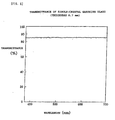
- Fig. 6 is a graph showing exemplary wavelength dependency of the transmittance of the light-transmissive alumina of the comparative example. This graph shows experimental results with light-transmissive alumina having a thickness of about 0.38 mm. The transmittance is substantially constant at about 75% in a range of 400 nm to 700 nm. Although the thickness condition in Fig. 6 differs from that in Fig. 5, the thickness dependency of the transmittance will be described later.
- the vertical axis in Fig. 6 is not ordinary transmittance, but is diffuse transmittance.
- diffuse transmission means transmission such that light diffuses in many directions regardless of the law of refraction when taking a broad view. For example, when light is transmitted by a light-transmissive material that is not transparent, such as frosted glass, the light undergoes diffuse transmission. As shown in Fig. 4, since the light-transmissive alumina is not transparent, light undergoes diffuse transmission.
- diffuse transmittance means transmittance of light (that is, the ratio of transmitted light intensity to incident light intensity) during such diffuse transmission.
- Fig. 7 is a graph showing exemplary thickness dependency of the diffuse transmittance of the light-transmissive alumina of the comparative example. It is estimated from this graph that the diffuse transmittance is about 66% to about 70% with the light-transmissive alumina having the same thickness (0.7 mm) as the single-crystal sapphire glass used in the graph in Fig. 5.
- the sapphire glass plate 308 is used in the above embodiment, the sapphire glass plate 308 is not necessarily formed of single-crystal sapphire glass. However, since the single-crystal sapphire glass has particularly high transparency and heat conductivity, the single-crystal sapphire glass may preferably be used.
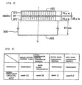
- Fig. 8(A) is a sectional view showing an exemplary modification of the above embodiment
- Fig. 8(B) is a front view thereof.
- the sapphire glass plate 308 is bonded to a holding frame 310 made of aluminum by an adhesive agent having superior heat conductivity (such as a silicone adhesive agent), and other configurations are the same as those of the above embodiment.
- the holding frame 310 has a rectangular opening 310a in the central part thereof. Light transmitted by the second polarizer 302Bo and the sapphire glass plate 308 passes through the opening 310a.
- heat of the second polarizer 302Bo is radiated not only from the sapphire glass plate 308, but also from the holding frame 310 made of aluminum, to the outside. Therefore, heat radiation efficiency can be further improved as compared to a case in which the holding frame 310 is not provided, and it is possible to further control the temperature rise of the second polarizer 302Bo. As a result, thermal stress generated inside the second polarizer 302Bo can be further reduced, and it is possible to further reduce inconsistencies in an image to be projected and displayed.
- the sapphire glass plate 308 is held in a state such that a space in which air can flow exists in at least a part of both surfaces (incident surface and emitting surface). Therefore, heat is also radiated by heat transfer on these two surfaces of the sapphire glass plate 308.
- the holding frame 310 is not limited to being aluminum, and it may be made of other types of metal. However, from the viewpoint of heat conductivity and lightness, a holding frame 310 made of aluminum may preferably be used.
- the sapphire glass plate 308 is not necessarily bonded on the holding frame 310, and it may be held on the holding frame 310 by other holding elements, such as by screws or by rivets. However, if the sapphire glass plate 308 and the holding frame 310 are bonded by an adhesive agent having superior heat conductivity, they are brought into face-to-face contact, and heat can therefore be transferred to the holding frame 310 more efficiently. From this point of view, they may preferably be bonded by the adhesive agent.
Landscapes
- Physics & Mathematics (AREA)
- Nonlinear Science (AREA)
- General Physics & Mathematics (AREA)
- Optics & Photonics (AREA)
- Crystallography & Structural Chemistry (AREA)
- Chemical & Material Sciences (AREA)
- Mathematical Physics (AREA)
- Engineering & Computer Science (AREA)
- Multimedia (AREA)
- Signal Processing (AREA)
- Projection Apparatus (AREA)
- Liquid Crystal (AREA)
- Polarising Elements (AREA)
Claims (10)
- Projektor, umfassend:worin die elektrooptische Vorrichtung einen Polarisator aufweist, der an zumindest einer der Seiten einer Lichteinfallsfläche und einer Lichtaustrittsfläche ausgebildet ist;ein Beleuchtungssystem zum Abgeben von Beleuchtungslicht;eine elektrooptische Vorrichtung zum Modulieren des Lichts von dem Beleuchtungssystem gemäß Bildinformation; undein Projektionssystem zum Projizieren eines von der elektrooptischen Vorrichtung erhaltenen modulierten Lichtstrahlflusses;
dadurch gekennzeichnet, dass
der Polarisator mit einer Saphirglasplatte verbunden ist. - Projektor nach Anspruch 1, worin die Saphirglasplatte aus Einkristall-Saphir gebildet ist.
- Projektor nach Anspruch 1 oder 2, worin die Saphirglasplatte durch einen aus Metall hergestellten Plattenelement-Halteabschnitt gehalten ist.
- Projektor nach Anspruch 3, worin die Saphirglasplatte und der Plattenelement-Halteabschnitt durch einen Klebstoff verbunden sind.
- Projektor nach einem der Ansprüche 1 bis 4, worin die Saphirglasplatte in einem derartigen Zustand gehalten ist, dass ein Raum, in dem Luft fließen kann, in zumindest einem Teil beider Oberflächen der Saphirglasplatte vorhanden ist.
- Projektor zum Projizieren und Anzeigen eines Farbbilds, umfassend:dadurch gekennzeichnet, dassein Beleuchtungssystem zum Abgeben von Beleuchtungslicht;ein Farblicht-Trennsystem zum Trennen des von dem Beleuchtungssystem abgegebenen Beleuchtungslichts in jeweilige erste bis dritte Farblichtkomponenten;erste bis dritte elektrooptische Vorrichtungen zum Modulieren der durch das Farblicht-Trennsystem getrennten ersten bis dritten Farblichtkomponenten gemäß Bildinformation, um erste bis dritte modulierte Lichtstrahlflüsse zu erzeugen;einen Farbsynthetisierabschnitt zum Synthetisieren der ersten bis dritten modulierten Lichtstrahlflüsse; undein Projektionssystem zum Projizieren des von dem Farbsynthetisierabschnitt abgegebenen synthetisierten Lichts;wobei jede der ersten bis dritten elektrooptischen Vorrichtungen einen Polarisator aufweist, der an zumindest einer der Seiten einer Lichteinfallsfläche und einer Lichtaustrittsfläche ausgebildet ist;
der Polarisator mit einer Saphirglasplatte verbunden ist. - Projektor nach Anspruch 2, worin die Saphirglasplatte aus Einkristall-Saphir gebildet ist.
- Projektor nach Anspruch 6 oder 7, worin die Saphirglasplatte durch einen aus Metall hergestellten Plattenelement-Halteabschnitt gehalten ist.
- Projektor nach Anspruch 8, worin die Saphirglasplatte und der Plattenelement-Halteabschnitt durch einen Klebstoff verbunden sind.
- Projektor nach einem der Ansprüche 6 bis 9, worin die Saphirglasplatte in einem derartigen Zustand gehalten ist, dass ein Raum, in dem Luft fließen kann, in zumindest einem Teil beider Oberflächen der Saphirglasplatte vorhanden ist.
Applications Claiming Priority (2)
| Application Number | Priority Date | Filing Date | Title |
|---|---|---|---|
| JP21312299 | 1999-07-28 | ||
| JP11213122A JP2001042424A (ja) | 1999-07-28 | 1999-07-28 | 投写型表示装置 |
Publications (2)
| Publication Number | Publication Date |
|---|---|
| EP1079263A1 EP1079263A1 (de) | 2001-02-28 |
| EP1079263B1 true EP1079263B1 (de) | 2003-03-12 |
Family
ID=16633950
Family Applications (1)
| Application Number | Title | Priority Date | Filing Date |
|---|---|---|---|
| EP00306385A Expired - Lifetime EP1079263B1 (de) | 1999-07-28 | 2000-07-27 | Projektor mit einem auf einem Substrat aus Saphir aufgebrachten Polarisator |
Country Status (8)
| Country | Link |
|---|---|
| US (1) | US6481850B1 (de) |
| EP (1) | EP1079263B1 (de) |
| JP (1) | JP2001042424A (de) |
| KR (1) | KR100380699B1 (de) |
| CN (1) | CN1135421C (de) |
| AT (1) | ATE234475T1 (de) |
| DE (1) | DE60001607T2 (de) |
| TW (1) | TW574549B (de) |
Families Citing this family (18)
| Publication number | Priority date | Publication date | Assignee | Title |
|---|---|---|---|---|
| JP2001272671A (ja) * | 2000-03-24 | 2001-10-05 | Seiko Epson Corp | プロジェクタ |
| JP4109901B2 (ja) * | 2001-05-29 | 2008-07-02 | キヤノン株式会社 | 画像表示装置 |
| US6747781B2 (en) * | 2001-06-25 | 2004-06-08 | Silicon Light Machines, Inc. | Method, apparatus, and diffuser for reducing laser speckle |
| JP4042474B2 (ja) * | 2001-08-08 | 2008-02-06 | セイコーエプソン株式会社 | 光学装置、およびプロジェクタ |
| US7202922B2 (en) * | 2002-03-26 | 2007-04-10 | Fuji Photo Film Co., Ltd. | Polarizing plate, and liquid crystal display |
| JP2004258621A (ja) * | 2003-02-06 | 2004-09-16 | Hitachi Displays Ltd | プロジェクタ用液晶表示装置 |
| JP2004245986A (ja) * | 2003-02-13 | 2004-09-02 | Seiko Epson Corp | プロジェクタ |
| US7139121B2 (en) * | 2004-06-18 | 2006-11-21 | Quickmate Company, Inc | Projection microscope |
| US7391569B2 (en) * | 2004-12-29 | 2008-06-24 | 3M Innovative Properties Company | Projection system including intrinsic polarizer |
| JP2006292947A (ja) * | 2005-04-08 | 2006-10-26 | Epson Toyocom Corp | 放熱用水晶板、偏光板、及び光学機器 |
| US20070002191A1 (en) * | 2005-07-01 | 2007-01-04 | Seiko Epson Corporation | Projector |
| JP4442687B2 (ja) * | 2007-12-12 | 2010-03-31 | セイコーエプソン株式会社 | プロジェクタ |
| JP2010181587A (ja) * | 2009-02-05 | 2010-08-19 | Sony Corp | 光変調装置および投射型表示装置 |
| JP5891742B2 (ja) * | 2011-11-25 | 2016-03-23 | セイコーエプソン株式会社 | 光学ユニット及びプロジェクター |
| DE102014221538A1 (de) * | 2014-10-23 | 2016-04-28 | Continental Automotive Gmbh | Head-up-Display |
| FR3053481B1 (fr) * | 2016-06-30 | 2018-08-17 | Valeo Comfort And Driving Assistance | Ecran a cristaux liquides, dispositif de generation d'image comprenant un tel ecran et afficheur tete haute comprenant un tel dispositif |
| JP6828438B2 (ja) * | 2017-01-06 | 2021-02-10 | セイコーエプソン株式会社 | 熱輸送装置及びプロジェクター |
| CN108287425B (zh) * | 2018-01-31 | 2022-01-28 | 京东方科技集团股份有限公司 | 一种偏光片及其制备方法、液晶面板 |
Family Cites Families (12)
| Publication number | Priority date | Publication date | Assignee | Title |
|---|---|---|---|---|
| CH613597B (de) * | 1975-08-14 | Bbc Brown Boveri & Cie | Hinter einem frontglas eines zeitmessgeraetes angeordnete fluessigkristallanzeige. | |
| JPH0476523A (ja) | 1990-07-18 | 1992-03-11 | Fujitsu Ltd | 液晶パネル |
| US5682216A (en) | 1996-04-01 | 1997-10-28 | Ctx Opto-Electronics Corp. | LCD projector capable of preventing thermal shimmering by using a thermal diffusion film |
| US6053615A (en) * | 1996-08-02 | 2000-04-25 | In Focus Systems, Inc. | Image projector with polarization conversion system |
| EP0867734B1 (de) | 1997-03-28 | 2005-06-08 | Seiko Epson Corporation | Optisches Beleuchtungssystem und Anzeigegerät vom Projektionstyp |
| JP3632436B2 (ja) | 1997-03-28 | 2005-03-23 | セイコーエプソン株式会社 | 照明光学系、およびこれを用いた投写型表示装置 |
| JPH11231277A (ja) | 1998-02-12 | 1999-08-27 | Sharp Corp | 液晶プロジェクター |
| JP3434193B2 (ja) | 1998-03-03 | 2003-08-04 | シャープ株式会社 | 透過型表示装置 |
| JP3091183B2 (ja) | 1998-03-27 | 2000-09-25 | 京セラ株式会社 | 液晶プロジェクタ装置 |
| US6245399B1 (en) * | 1998-10-14 | 2001-06-12 | 3M Innovative Properties Company | Guest-host polarizers |
| US6172816B1 (en) * | 1998-10-23 | 2001-01-09 | Duke University | Optical component adjustment for mitigating tolerance sensitivities |
| EP1016894A3 (de) | 1998-12-28 | 2001-03-28 | Kyocera Corporation | Flüssigkristallanzeige |
-
1999
- 1999-07-28 JP JP11213122A patent/JP2001042424A/ja active Pending
-
2000
- 2000-06-14 TW TW089111646A patent/TW574549B/zh not_active IP Right Cessation
- 2000-07-06 US US09/612,519 patent/US6481850B1/en not_active Expired - Lifetime
- 2000-07-27 CN CNB00122543XA patent/CN1135421C/zh not_active Expired - Fee Related
- 2000-07-27 EP EP00306385A patent/EP1079263B1/de not_active Expired - Lifetime
- 2000-07-27 DE DE60001607T patent/DE60001607T2/de not_active Expired - Lifetime
- 2000-07-27 AT AT00306385T patent/ATE234475T1/de not_active IP Right Cessation
- 2000-07-27 KR KR10-2000-0043302A patent/KR100380699B1/ko not_active Expired - Fee Related
Also Published As
| Publication number | Publication date |
|---|---|
| JP2001042424A (ja) | 2001-02-16 |
| ATE234475T1 (de) | 2003-03-15 |
| KR20010030018A (ko) | 2001-04-16 |
| EP1079263A1 (de) | 2001-02-28 |
| US6481850B1 (en) | 2002-11-19 |
| CN1135421C (zh) | 2004-01-21 |
| DE60001607D1 (de) | 2003-04-17 |
| DE60001607T2 (de) | 2003-10-09 |
| KR100380699B1 (ko) | 2003-04-18 |
| CN1282885A (zh) | 2001-02-07 |
| TW574549B (en) | 2004-02-01 |
Similar Documents
| Publication | Publication Date | Title |
|---|---|---|
| EP1079263B1 (de) | Projektor mit einem auf einem Substrat aus Saphir aufgebrachten Polarisator | |
| US5200843A (en) | Polarized synthesization in projection type liquid crystal displays | |
| TW401531B (en) | Projection type liquid crystal display | |
| WO1998053364A1 (en) | Light-modulating element and projection display | |
| US7551280B2 (en) | Method for manufacturing optical element, method for manufacturing projector, optical element and projector | |
| US8730433B2 (en) | Coupling structure for wire grid type inorganic polarizer and video projector including the same | |
| US6619800B1 (en) | Projector comprising a polarizer attached to a transmissive flexible plate material that bends responsive to changes in the shape of the polarizer | |
| US20060262233A1 (en) | Liquid crystal projector | |
| JP3049752B2 (ja) | 投写型表示装置 | |
| JP2004245914A (ja) | 液晶プロジェクタ装置とそれに用いる透明板及び液晶表示パネル | |
| JP2000356770A (ja) | 液晶プロジェクタ | |
| US10921692B2 (en) | Optical mechanism and projection device | |
| JP3389541B2 (ja) | 投写型表示装置 | |
| US20070132954A1 (en) | Projector and optical part | |
| CN1135419C (zh) | 光学系统和投射型显示装置 | |
| US7969516B2 (en) | Projector | |
| US7819534B2 (en) | Projector and method for manufacturing projector | |
| JP2001201739A (ja) | 投射型映像表示装置及び光学部品 | |
| US6612702B1 (en) | Projection display device | |
| JP2001215491A (ja) | 偏光ビームスプリッタ及びそれを用いた反射型液晶プロジェクタ | |
| JP2571948Y2 (ja) | ミラー取り付け機構 | |
| JP3979106B2 (ja) | 液晶プロジェクタ | |
| JP2005181719A (ja) | 液晶パネルブロック | |
| JP2001042279A (ja) | 液晶プロジェクタ | |
| JP2537607C (de) |
Legal Events
| Date | Code | Title | Description |
|---|---|---|---|
| PUAI | Public reference made under article 153(3) epc to a published international application that has entered the european phase |
Free format text: ORIGINAL CODE: 0009012 |
|
| AK | Designated contracting states |
Kind code of ref document: A1 Designated state(s): AT BE CH CY DE DK ES FI FR GB GR IE IT LI LU MC NL PT SE |
|
| AX | Request for extension of the european patent |
Free format text: AL;LT;LV;MK;RO;SI |
|
| 17P | Request for examination filed |
Effective date: 20010718 |
|
| AKX | Designation fees paid |
Free format text: AT BE CH CY DE DK ES FI FR GB GR IE IT LI LU MC NL PT SE |
|
| 17Q | First examination report despatched |
Effective date: 20011119 |
|
| GRAH | Despatch of communication of intention to grant a patent |
Free format text: ORIGINAL CODE: EPIDOS IGRA |
|
| GRAH | Despatch of communication of intention to grant a patent |
Free format text: ORIGINAL CODE: EPIDOS IGRA |
|
| GRAA | (expected) grant |
Free format text: ORIGINAL CODE: 0009210 |
|
| AK | Designated contracting states |
Designated state(s): AT BE CH CY DE DK ES FI FR GB GR IE IT LI LU MC NL PT SE |
|
| PG25 | Lapsed in a contracting state [announced via postgrant information from national office to epo] |
Ref country code: IT Free format text: LAPSE BECAUSE OF FAILURE TO SUBMIT A TRANSLATION OF THE DESCRIPTION OR TO PAY THE FEE WITHIN THE PRESCRIBED TIME-LIMIT;WARNING: LAPSES OF ITALIAN PATENTS WITH EFFECTIVE DATE BEFORE 2007 MAY HAVE OCCURRED AT ANY TIME BEFORE 2007. THE CORRECT EFFECTIVE DATE MAY BE DIFFERENT FROM THE ONE RECORDED. Effective date: 20030312 Ref country code: AT Free format text: LAPSE BECAUSE OF FAILURE TO SUBMIT A TRANSLATION OF THE DESCRIPTION OR TO PAY THE FEE WITHIN THE PRESCRIBED TIME-LIMIT Effective date: 20030312 Ref country code: CH Free format text: LAPSE BECAUSE OF FAILURE TO SUBMIT A TRANSLATION OF THE DESCRIPTION OR TO PAY THE FEE WITHIN THE PRESCRIBED TIME-LIMIT Effective date: 20030312 Ref country code: LI Free format text: LAPSE BECAUSE OF FAILURE TO SUBMIT A TRANSLATION OF THE DESCRIPTION OR TO PAY THE FEE WITHIN THE PRESCRIBED TIME-LIMIT Effective date: 20030312 Ref country code: NL Free format text: LAPSE BECAUSE OF FAILURE TO SUBMIT A TRANSLATION OF THE DESCRIPTION OR TO PAY THE FEE WITHIN THE PRESCRIBED TIME-LIMIT Effective date: 20030312 Ref country code: GR Free format text: LAPSE BECAUSE OF FAILURE TO SUBMIT A TRANSLATION OF THE DESCRIPTION OR TO PAY THE FEE WITHIN THE PRESCRIBED TIME-LIMIT Effective date: 20030312 Ref country code: BE Free format text: LAPSE BECAUSE OF FAILURE TO SUBMIT A TRANSLATION OF THE DESCRIPTION OR TO PAY THE FEE WITHIN THE PRESCRIBED TIME-LIMIT Effective date: 20030312 Ref country code: FI Free format text: LAPSE BECAUSE OF FAILURE TO SUBMIT A TRANSLATION OF THE DESCRIPTION OR TO PAY THE FEE WITHIN THE PRESCRIBED TIME-LIMIT Effective date: 20030312 |
|
| REG | Reference to a national code |
Ref country code: GB Ref legal event code: FG4D |
|
| REG | Reference to a national code |
Ref country code: CH Ref legal event code: EP |
|
| REG | Reference to a national code |
Ref country code: IE Ref legal event code: FG4D |
|
| REF | Corresponds to: |
Ref document number: 60001607 Country of ref document: DE Date of ref document: 20030417 Kind code of ref document: P |
|
| PG25 | Lapsed in a contracting state [announced via postgrant information from national office to epo] |
Ref country code: SE Free format text: LAPSE BECAUSE OF FAILURE TO SUBMIT A TRANSLATION OF THE DESCRIPTION OR TO PAY THE FEE WITHIN THE PRESCRIBED TIME-LIMIT Effective date: 20030612 Ref country code: DK Free format text: LAPSE BECAUSE OF FAILURE TO SUBMIT A TRANSLATION OF THE DESCRIPTION OR TO PAY THE FEE WITHIN THE PRESCRIBED TIME-LIMIT Effective date: 20030612 |
|
| PG25 | Lapsed in a contracting state [announced via postgrant information from national office to epo] |
Ref country code: PT Free format text: LAPSE BECAUSE OF FAILURE TO SUBMIT A TRANSLATION OF THE DESCRIPTION OR TO PAY THE FEE WITHIN THE PRESCRIBED TIME-LIMIT Effective date: 20030616 |
|
| PG25 | Lapsed in a contracting state [announced via postgrant information from national office to epo] |
Ref country code: LU Free format text: LAPSE BECAUSE OF NON-PAYMENT OF DUE FEES Effective date: 20030727 Ref country code: CY Free format text: LAPSE BECAUSE OF FAILURE TO SUBMIT A TRANSLATION OF THE DESCRIPTION OR TO PAY THE FEE WITHIN THE PRESCRIBED TIME-LIMIT Effective date: 20030727 |
|
| PG25 | Lapsed in a contracting state [announced via postgrant information from national office to epo] |
Ref country code: IE Free format text: LAPSE BECAUSE OF NON-PAYMENT OF DUE FEES Effective date: 20030728 |
|
| PG25 | Lapsed in a contracting state [announced via postgrant information from national office to epo] |
Ref country code: MC Free format text: LAPSE BECAUSE OF NON-PAYMENT OF DUE FEES Effective date: 20030731 |
|
| NLV1 | Nl: lapsed or annulled due to failure to fulfill the requirements of art. 29p and 29m of the patents act | ||
| ET | Fr: translation filed | ||
| REG | Reference to a national code |
Ref country code: CH Ref legal event code: PL |
|
| PG25 | Lapsed in a contracting state [announced via postgrant information from national office to epo] |
Ref country code: ES Free format text: LAPSE BECAUSE OF FAILURE TO SUBMIT A TRANSLATION OF THE DESCRIPTION OR TO PAY THE FEE WITHIN THE PRESCRIBED TIME-LIMIT Effective date: 20030930 |
|
| PLBE | No opposition filed within time limit |
Free format text: ORIGINAL CODE: 0009261 |
|
| STAA | Information on the status of an ep patent application or granted ep patent |
Free format text: STATUS: NO OPPOSITION FILED WITHIN TIME LIMIT |
|
| 26N | No opposition filed |
Effective date: 20031215 |
|
| REG | Reference to a national code |
Ref country code: IE Ref legal event code: MM4A |
|
| REG | Reference to a national code |
Ref country code: FR Ref legal event code: PLFP Year of fee payment: 17 |
|
| REG | Reference to a national code |
Ref country code: FR Ref legal event code: PLFP Year of fee payment: 18 |
|
| PGFP | Annual fee paid to national office [announced via postgrant information from national office to epo] |
Ref country code: FR Payment date: 20170613 Year of fee payment: 18 |
|
| PGFP | Annual fee paid to national office [announced via postgrant information from national office to epo] |
Ref country code: GB Payment date: 20170726 Year of fee payment: 18 Ref country code: DE Payment date: 20170719 Year of fee payment: 18 |
|
| REG | Reference to a national code |
Ref country code: DE Ref legal event code: R119 Ref document number: 60001607 Country of ref document: DE |
|
| GBPC | Gb: european patent ceased through non-payment of renewal fee |
Effective date: 20180727 |
|
| PG25 | Lapsed in a contracting state [announced via postgrant information from national office to epo] |
Ref country code: FR Free format text: LAPSE BECAUSE OF NON-PAYMENT OF DUE FEES Effective date: 20180731 Ref country code: GB Free format text: LAPSE BECAUSE OF NON-PAYMENT OF DUE FEES Effective date: 20180727 Ref country code: DE Free format text: LAPSE BECAUSE OF NON-PAYMENT OF DUE FEES Effective date: 20190201 |