EP1079571B1 - Routage optique de pacquets dans un système de réseau basé sur une technique de commutation d'étiquettes optiques - Google Patents
Routage optique de pacquets dans un système de réseau basé sur une technique de commutation d'étiquettes optiquesInfo
- Publication number
- EP1079571B1 EP1079571B1 EP00307358A EP00307358A EP1079571B1 EP 1079571 B1 EP1079571 B1 EP 1079571B1 EP 00307358 A EP00307358 A EP 00307358A EP 00307358 A EP00307358 A EP 00307358A EP 1079571 B1 EP1079571 B1 EP 1079571B1
- Authority
- EP
- European Patent Office
- Prior art keywords
- optical
- wavelength
- source equipment
- signal
- signals
- Prior art date
- Legal status (The legal status is an assumption and is not a legal conclusion. Google has not performed a legal analysis and makes no representation as to the accuracy of the status listed.)
- Expired - Lifetime
Links
Images







Classifications
-
- H—ELECTRICITY
- H04—ELECTRIC COMMUNICATION TECHNIQUE
- H04B—TRANSMISSION
- H04B10/00—Transmission systems employing electromagnetic waves other than radio-waves, e.g. infrared, visible or ultraviolet light, or employing corpuscular radiation, e.g. quantum communication
-
- H—ELECTRICITY
- H04—ELECTRIC COMMUNICATION TECHNIQUE
- H04Q—SELECTING
- H04Q11/00—Selecting arrangements for multiplex systems
- H04Q11/0001—Selecting arrangements for multiplex systems using optical switching
- H04Q11/0005—Switch and router aspects
-
- H—ELECTRICITY
- H04—ELECTRIC COMMUNICATION TECHNIQUE
- H04B—TRANSMISSION
- H04B10/00—Transmission systems employing electromagnetic waves other than radio-waves, e.g. infrared, visible or ultraviolet light, or employing corpuscular radiation, e.g. quantum communication
- H04B10/27—Arrangements for networking
-
- H—ELECTRICITY
- H04—ELECTRIC COMMUNICATION TECHNIQUE
- H04Q—SELECTING
- H04Q11/00—Selecting arrangements for multiplex systems
- H04Q11/0001—Selecting arrangements for multiplex systems using optical switching
- H04Q11/0062—Network aspects
-
- H—ELECTRICITY
- H04—ELECTRIC COMMUNICATION TECHNIQUE
- H04Q—SELECTING
- H04Q11/00—Selecting arrangements for multiplex systems
- H04Q11/0001—Selecting arrangements for multiplex systems using optical switching
- H04Q11/0062—Network aspects
- H04Q11/0066—Provisions for optical burst or packet networks
-
- H—ELECTRICITY
- H04—ELECTRIC COMMUNICATION TECHNIQUE
- H04Q—SELECTING
- H04Q11/00—Selecting arrangements for multiplex systems
- H04Q11/0001—Selecting arrangements for multiplex systems using optical switching
- H04Q11/0005—Switch and router aspects
- H04Q2011/0007—Construction
- H04Q2011/0011—Construction using wavelength conversion
-
- H—ELECTRICITY
- H04—ELECTRIC COMMUNICATION TECHNIQUE
- H04Q—SELECTING
- H04Q11/00—Selecting arrangements for multiplex systems
- H04Q11/0001—Selecting arrangements for multiplex systems using optical switching
- H04Q11/0005—Switch and router aspects
- H04Q2011/0007—Construction
- H04Q2011/0016—Construction using wavelength multiplexing or demultiplexing
-
- H—ELECTRICITY
- H04—ELECTRIC COMMUNICATION TECHNIQUE
- H04Q—SELECTING
- H04Q11/00—Selecting arrangements for multiplex systems
- H04Q11/0001—Selecting arrangements for multiplex systems using optical switching
- H04Q11/0005—Switch and router aspects
- H04Q2011/0007—Construction
- H04Q2011/0032—Construction using static wavelength routers (e.g. arrayed waveguide grating router [AWGR] )
-
- H—ELECTRICITY
- H04—ELECTRIC COMMUNICATION TECHNIQUE
- H04Q—SELECTING
- H04Q11/00—Selecting arrangements for multiplex systems
- H04Q11/0001—Selecting arrangements for multiplex systems using optical switching
- H04Q11/0005—Switch and router aspects
- H04Q2011/0037—Operation
- H04Q2011/0041—Optical control
-
- H—ELECTRICITY
- H04—ELECTRIC COMMUNICATION TECHNIQUE
- H04Q—SELECTING
- H04Q11/00—Selecting arrangements for multiplex systems
- H04Q11/0001—Selecting arrangements for multiplex systems using optical switching
- H04Q11/0062—Network aspects
- H04Q2011/0069—Network aspects using dedicated optical channels
-
- H—ELECTRICITY
- H04—ELECTRIC COMMUNICATION TECHNIQUE
- H04Q—SELECTING
- H04Q11/00—Selecting arrangements for multiplex systems
- H04Q11/0001—Selecting arrangements for multiplex systems using optical switching
- H04Q11/0062—Network aspects
- H04Q2011/0073—Provisions for forwarding or routing, e.g. lookup tables
-
- H—ELECTRICITY
- H04—ELECTRIC COMMUNICATION TECHNIQUE
- H04Q—SELECTING
- H04Q11/00—Selecting arrangements for multiplex systems
- H04Q11/0001—Selecting arrangements for multiplex systems using optical switching
- H04Q11/0062—Network aspects
- H04Q2011/0079—Operation or maintenance aspects
- H04Q2011/0083—Testing; Monitoring
Definitions
- the present invention relates to an optical packet routing system for routing an optical signal by using the optical label signal carrying the control information necessary for the routing of the optical signal, more particularly, to a multiple-wavelength optical source unit to be used for a network system whose a plurality of communication nodes are connected by the wavelength routing system and an optical communication unit and an optical communication method to be used for an optical communication system whose internode communication among the communication nodes is made through a routing unit.
- any optical signal fed into a given input port can be routed selectively to different output ports according to its wavelength without being converted into an electric signal, by using an optical device (e.g., arrayed-waveguide grating) having a wavelength selectivity.
- an optical device e.g., arrayed-waveguide grating
- FIG. 2 schematically illustrates the general composition of the network system interconnecting a plurality of communication nodes by utilizing the wavelength routing function of the cyclic-wavelength arrayed-waveguide grating.
- the optical signal transmitted from a communication node is routed in the form of the light according to its wavelength without undergoing any electrical processing for routing, so that high-speed routing is possible.
- the network system comprises N number of communication nodes 30 (communication nodes #1-N) and a cyclic-wavelength arrayed- waveguide grating 60 having a wavelength routing processing function.
- Each communication node 30 comprises transmitter equipment 40 and receiver equipment 50.
- the transmitter equipment 40 comprises N number of optical sources 41 for transmitting optical signals having wavelengths ⁇ 1- ⁇ n.
- the optical signals (wavelength: ⁇ 1- ⁇ n) transmitted from the transmitter equipment 40 of each communication node 30 are introduced into the input ports of the cyclic-wavelength arrayed-waveguide grating 60 having the wavelength routing processing function.
- the cyclic-wavelength arrayed-waveguide grating 60 routes the optical signals incoming from various communication nodes 30 to different output ports according to the wavelengths, ⁇ 1- ⁇ n, of the optical signals. Since this routing processing of the optical signal is carried out according to the wavelength of the optical signal while maintaining the form of the light without being subjected to any electrical processing, the high-speed routing is possible.
- optical signals (wavelength: ⁇ 1- ⁇ n) came out from the output ports of the cyclic-wavelength arrayed-waveguide grating 60 is introduced into the receiver equipment 50 in each communication node 30.
- Optical signals (wavelength: ⁇ 1- ⁇ 4) varying in wavelength transmitted from various communication nodes (#1-#4) are fed to the input ports 61a-61d of the cyclic-wavelength arrayed-waveguide grating 60.
- the optical signal transmitted from the communication node #1 to the input node 61a is outputted from the output port 62a when its wavelength is ⁇ 1, from the output port 62b when its wavelength is ⁇ 2, from the output port 62c when the wavelength is ⁇ 3 and from 62d when the wavelength is ⁇ 4.
- the optical signal to be transmitted from the communication node #2 to the input port 61b is outputted from the output port 62d when its wavelength is ⁇ 1, from the output port 62a when its wavelength is ⁇ 2, from the output port 62b when its wavelength is ⁇ 3, and from the output port 62c when its wavelength is ⁇ 4.
- the optical signal to be transmitted from the communication node #3 is outputted from the output port 62c when its wavelength is ⁇ 1, from the output port 62d when its wavelength is ⁇ 2, and from the output port 62a when its wavelength is ⁇ 3, and from the output port 62b when its wavelength is ⁇ 4.
- the optical signal to be transmitted from the communication node #4 to the input port 61d is outputted from the output port 62b when its wavelength is ⁇ 1, from the output port 62c when its wavelength is ⁇ 2, from the output port 62d when its wavelength is ⁇ 3, and from the output port 62a when its wavelength is ⁇ 4.
- the wavelength routing by using the cyclic-wavelength arrayed-waveguide grating as is shown in FIG. 3 is characterized by that the optical signals having the same wavelengths fed to different input ports of the grating are outputted from different output ports of the grating respectively, so that the conflict among the data having the same wavelengths with respect to the output port can be prevented.
- N number of optical sources with wavelengths strictly adapted to the wavelength characteristic of the cyclic-wavelength arrayed-waveguide grating with respect to each of the communication nodes and thus requiring N x N number of optical sources, which is a problem to be resolved.
- providing N number of optical sources for each communication node not only results in the increase in the burdens such as the increase in the size and cost of the communication node but also results in the increase in total cost of the network system.
- the communication nodes 100a-100d are respectively provided with one of the corresponding optical signal transmitters 71a-71d for respectively transmitting one of the corresponding optical signals 76a-76d and also respectively provided with one of the corresponding optical label signal transmitters 72a-72d for respectively transmitting one of the corresponding optical label signals 77a-77d carrying the control information necessary for the routing of the optical signal.
- the routing device 80 is connected respectively to each communication nodes 100a-100d through the corresponding optical transmission lines 81a-81d and comprises wavelength demultiplexers 74 for separating the optical signals and the optical label signals, optical receivers 78e for receiving the optical label signals separated by the wavelength multiplexers 74, optical splitters 79 for branching the optical signals separated by the wavelength demultiplexers 74 to a plurality of optical paths and a plurality of optical gates 75a-75d for selecting the optical path by the routing processing for passing or intercepting the optical signals according to the control information in the optical label signals 77a-77d respectively connected to a plurality of the corresponding optical paths.
- the control circuit section for controlling the optical gates 75a-75d are not shown in the figure.
- the optical signals 76a-76d and the optical label signals 77a-77d respectively including the control routing information of the optical signals are fed respectively to the router 80 through the optical transmission lines 81a-81d after being transmitted respectively from a plurality of communication nodes 100a-100d (the four communication nodes #1-#4 in the case shown in the figure), the optical signals 76a-76d and the optical label signals 77a-77d are respectively separated by the wavelength demultiplexers 74 provided in the router 80 respectively corresponding to the communication nodes.
- the optical signals 76a-76d are respectively branched by the optical splitter 79 in the stage following the wavelength demultiplexer 74 and respectively introduced into the corresponding optical gates (three optical gates among the optical gates 75a-75d in the case shown in the figure) through a plurality of optical paths of substantially the same length (three optical paths in the case shown in the figure).
- the optical label signals 77a-77d are respectively guided to the corresponding optical receivers 78e.
- the optical path for the optical signal is selected from among the optical paths 82a-82d.
- the time required for the optical signal 76 (the representative number of 76a-76d) to arrive at the optical gate 75 (the representative number of 75a-75d) from the input port of the wavelength demultiplexer 74 of the router 80 is given as t1;
- the time required for the optical label signal 77 (the representative number of 77a-77d) corresponding to the optical signal 76 to arrive at the optical receiver 78e from the input port of the wavelength demultiplexer 74 is given as t2;
- each of the communication nodes 100 (the representative number of 100a-100d) to output both the optical signal 76 and the optical label signal 77 respectively with a time lag so that the time lag becomes equal to the relative time lag T' (the time lag between the front of the optical signal 76 and the end of optical label signal 77 arrived at the input port of the wavelength demultiplexer 74, denoted by numeral 90 in FIG. 5) to satisfy the inequality (1) given below.
- T ′ > t 2 + t 3 ⁇ t 1
- the relative time lag T' between the optical signal 76 and the optical label signal 77 which is necessary for proper gating of the optical signal 76 by the optical gate 75, can be determined.
- the relative time lag between the optical signal and the optical label signal varies according to transmission distance due to the effect of the wavelength dispersion of the optical fiber which is a transmission medium of the optical signal.
- the time lag T between the transmission of the optical signal and that of the optical label signal set by the communication node 100 differs from the relative time lag T' at immediately before the input port of the wavelength demultiplexer 74 of the router 80.
- EP 0 223 258 discloses a wavelength division optical switching system and a communications network which are free from interchannel interference that is realised using light modulation techniques for conversion of light wavelength.
- FR 2 709 839 discloses an optical multiplexer that uses optical packets constituted of a switching address and useful message to realise automatic optical routing of optical packets.
- the present invention has been made in consideration of the problems of the related arts, and from a new viewpoint that is not expected in the conventional methods.
- the first object of the present invention concerning the first embodiment of the present invention to provide an optical communication device capable of resolving the previously mentioned problem of the conventional wavelength routing by drastically reducing the number of optical sources necessary for each communication node by providing shared optical sources to be shared among a plurality of communication nodes so that the number of required optical sources in each of the communication nodes is reduced and each of the communication nodes is not required to be provided with its own optical source having the wavelength strictly adjusted for data transmission.
- Another object relating to the first embodiment of the present invention is to provide an optical communication device capable of forming a simple system not requiring each communication node to be provided with its own optical sources having its wavelength strictly adjusted for data transmission.
- a multi-wavelength optical source equipment employed for an optical network system with a plurality of communication nodes connected with one another by a wavelength routing method and for converting the wavelength of the optical signals to desired wavelengths so as to transmit to desired communication nodes, the optical signals carrying the control information concerning the routing of the signals from each of the communication nodes, comprising : first optical splitters for branching the optical signals transmitted from each of the communication nodes to a first optical path and a second optical path; optical receivers for receiving the optical signals that have passed the first optical path; second optical splitters for branching the optical signals that have passed the second optical path to a plurality of optical paths; a plurality of optical gates for passing or intercepting the optical signals branched by the second splitters; wavelength converters for converting the wavelength of the optical signals outputted from the optical gates into desired wavelengths; a controller for controlling optical gates according to the control information relating to the routing of the optical signals received by the optical receivers; optical delay devices for adjusting the optical path length so that the optical signals that
- multi-wavelength optical source equipment having shared multi-wavelength optical sources and a wavelength conversion function, is provided between each the communication node and the wavelength router and is shared by each communication node.
- the wavelength of the optical signals transmitted from each communication node can be converted into the wavelengths adapted for routing to desired communication nodes by using the light provided from the shared multi-wavelength optical sources, whereby for a plurality of communication nodes interconnected by the wavelength routing system, the number of the optical sources for the data transmission provided for each communication node, which results in the building of a low-cost system.
- the wavelength of the principal optical signals transmitted from each communication node are converted into the wavelengths necessary for the wavelength routing by the multi-wavelength optical source equipment, so that it is not necessary to provide optical sources having strictly defined wavelength for each communication node, thereby making easier the system configuration.
- the transmission bit rate of the data increases, it is possible to reduce the load of the electrical processing for reading the routing information of the data by transmitting the routing information of the data with a low bit-rate optical signal having the wavelength differing from the data signal.
- the status information of data transmissions from the communication nodes can be converged to the multi-wavelength optical source equipment, so that the control of the network can be made easier.
- the optical packet routing system by using the optical label signals according to the present invention can be expected to be capable of contributing to the development of the optical communication systems such as Metropolitan Area Network (MAN), a communication carrier, Wide Area Network (WAN), those for business enterprises, those for universities such as the campus area networks and the like.
- MAN Metropolitan Area Network
- WAN Wide Area Network
- those for business enterprises those for universities
- universities such as the campus area networks and the like.
- optical packet routing network system The configurations and operations of optical packet routing network system according to the embodiments of the present invention will be described below with reference to the drawings.
- FIG. 7 schematically shows the composition of the network system provided with the multi-wavelength optical source equipment relating to the present invention.
- the network system comprises N number (4 in the present embodiment) of communication nodes 30 (i.e., communication node #1-communication node #4), multi-wavelength optical source equipment 70 relating to the present invention and the cyclic-wavelength arrayed-waveguide grating 60 having wavelength routing function.
- Each communication node 30 is provided with transmitter equipment 40 and receiver equipment 50.
- the transmitter equipment 40 of the communication node #1 is provided with optical sources 41 for transmitting an optical signal having a single wavelength ⁇ a.
- the communication node #2 has an optical source 41 for transmitting optical signals having a single wavelength ⁇ b;
- the communication node #3 has an optical source 41 for transmitting optical signals having a single wavelength ⁇ c;
- the communication node #4 has an optical source 41 for transmitting optical signals having a single wavelength ⁇ d.
- These wavelengths, ⁇ a, ⁇ b, ⁇ c and ⁇ d are predetermined.
- Multi-wavelength optical source equipment 70 incorporates N number of shared optical sources corresponding to the N number of the communication nodes. Since this embodiment comprises 4 communication nodes, the multi-wavelength optical source equipment 70 incorporates 4 optical sources 8a, 8b, 8c and 8d. Further, the multi-wavelength optical source equipment 70 comprises input ports and output ports respectively the corresponding in number to the number of the communication nodes. In the case of the present embodiment, the multi-wavelength optical source equipment 70 is provided with 4 input ports 1a-1d and 4 output ports 2a-2d. The input ports 1a-1d are connected to the transmitter equipment 40 of the corresponding communication nodes #1-#4 respectively. The output ports 2a-2d are connected to the corresponding input ports 61a-61d of the cyclic-wavelength arrayed-waveguide grating 60 respectively.
- the output ports 62a-62d of the cyclic-wavelength arrayed-waveguide grating 60 are connected to the receiver equipment 50 of the corresponding communication nodes #1-#4.
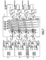
- FIG. 8 the internal structure of the multi-wave optical source equipment 70 will be described referring to FIG. 8.
- 4 input ports and 4 output ports are provided respectively, but the numbers are not necessarily be limited to 4 in the case of the present invention.
- numeral 3 denotes a 1 x 2 optical splitter comprising 1 input port and 2 output ports.
- Numerals 4, 5, 6 and 7 denote an optical delay device, an optical receiver, an optical gate and an optical gate control system (controller) respectively.
- Numerals 8a-8d are shared optical sources for emitting the optical lights having the wavelengths ⁇ a, ⁇ b, ⁇ c and ⁇ d.
- Numeral 9 denotes a 1 x 4 optical splitter comprising 1 input port and 4 output ports.
- Numerals 10a-10d denote wavelength converters.
- Numerals 11 denotes a wavelength multiplexer comprising 2 input ports and 1 output port.
- Numerals 12 denotes a wavelength multiplexer comprising 4 input ports and 1 output port.
- Numeral 13 denotes an optical line.
- Numerals 14a-14d denote optical lines connecting individual communication nodes 30 and the individual input ports 1a-1d of the multi-wavelength optical source equipment 70.
- Numerals 15a-15d are optical lines connecting the output ports 2a-2d of the multi-wavelength optical source equipment 70 and the input ports 61a-61d of the cyclic-wavelength arrayed-waveguide grating 60.
- Numeral 16 denotes an electric line connecting the optical receiver 5 and the optical gate control system 7.
- silica glass waveguide type optical splitters may be employed as the optical splitters 3 and 9; an optical fiber type optical delay device, as the optical delay device 4; a device using a semiconductor optical amplifier, as the optical gate 6; distributed feedback type semiconductor lasers, as the shared sources 8a-8d; a device using semiconductor amplifier, as wavelength converters 10a-10d; a silica glass waveguide type wavelength multiplexer, as the wavelength multiplexer 11; an arrayed-waveguide grating, as the wavelength multiplexer 12; an optical fiber, as the optical line 13.
- an optical fiber type optical delay device as the optical delay device 4
- a device using a semiconductor optical amplifier as the optical gate 6
- distributed feedback type semiconductor lasers as the shared sources 8a-8d
- a device using semiconductor amplifier as wavelength converters 10a-10d
- a silica glass waveguide type wavelength multiplexer as the wavelength multiplexer 11
- an arrayed-waveguide grating as the wavelength multiplexer 12
- an optical fiber as the optical line 13.
- the optical signal S12 sent out from the communication node #1 to the communication node #2 is fed to the input port 1a of the multi-wavelength optical source equipment 70.
- This optical signal is composed of a data component and a control component for employed selecting the optical gates and the like to direct the designation communication node, both the components having an identical wavelength ⁇ a.
- the control component of the optical signal is designated as the optical label signal.
- the optical signal fed to the input port 1a is branched to the first optical path 22 and the second optical path 23 by means of the optical splitter 3.
- the optical signal branched to the first optical path is guided to the optical receiver 5 that is connected with the control system 7.
- the optical signal branched to the second optical path is guided to each of the four optical gates 6 through an optical fiber type optical delay device 4 and the optical splitter 9.
- control system 7 analyzes the control information contained in the control component of the optical signal received by the optical receiver 5 and the control system 7. According to the result of analysis, the control system 7 outputs the control signal for the gate selection to the optical gates 6.
- One or plural optical gate(s) 6 are selected according to the control signal (i.e., the control component for the selection of optical gates) from the control system 7, and the optical signal is outputted from the output port of one or plural selected optical gate(s) 6.
- Individual output ports of the optical gates 6 are respectively connected to the corresponding wavelength converters 10a, 10b, 10c and 10d through the wavelength multiplexers 11.
- the optical signal outputted from the output port of one or plural selected optical gate(s) is fed to the input port of the wavelength converter 10i (i represents any one of a, b, c and d) connected to the selected optical gate 6.
- the wavelength converter 10i converts the wavelength of the inputted optical signal into the wavelength (i.e., wavelength ⁇ 12, provided that the wavelength may be any one of ⁇ 1- ⁇ 4) for the routing to the addressed communication node #2.
- the optical signal whose wavelength is converted into ⁇ 12 by the wavelength converter 10i is guided to one of the input ports 61a-61d (Refer to FIG. 7) of the cyclic-wavelength arrayed-waveguide grating 60 connected to the output ports 2a-2d of the multi-wavelength optical source equipment 70.
- the output port leading to the communication node 30 is selected which is specified by the control component of the optical signal according to the wavelength ⁇ 12 of the optical signal by means of the wavelength routing as is described in connection with the prior art.
- the output port leading to the communication node #2 is selected. In this way, the optical signal is routed by the cyclic-wavelength arrayed-waveguide grating 60 so as to be received by the addressed communication node #2.
- the wavelength of an optical signal transmitted from any communication node 30 to one or plural desired communication node(s) is converted into one or plural wavelength(s) by means of the multi-wavelength optical source equipment 70 according to the present invention in response to the control component of the optical signal and the optical signal is made to be received by one or plural addressed communication node(s) 30 by means of the cyclic-wavelength arrayed-waveguide grating 60 having the wavelength routing function.
- the multi-wavelength optical source equipment 70 is provided with shared multi-wavelength optical sources 8a-8d, which can be shared among the communication nodes 30 (communication nodes #1-#4) and give the light with appropriate wavelengths necessary for the wavelength routing to the wavelength converters 10a-10d from these optical sources 8a-8d and providing to each communication nodes 30. Therefore, eight optical sources in total, that is, the four optical sources in the communication nodes 30 and another four optical sources in the multi-wavelength optical source equipment 70, is sufficient for this optical network system.
- N x N N 2
- the number of optical sources required by each communication node can be reduced largely, and the effect of such reduction become larger as the number of the communication nodes constituting the optical network increases.
- the wavelengths ( ⁇ a - ⁇ d) of the optical sources 41 for employed transmitting, provided in individual communication nodes 30 are converted into those of the optical sources 8a-8d by means of the wavelength converters 10a-10d, the wavelengths of the optical sources 41 are not necessarily required to be strictly controlled wavelengths. Therefore, the work load for setting the wavelength of each of the communication nodes 30 can be reduced.
- the explanation has been made as to the examples of the case in which the silica glass optical waveguide type optical splitter is employed as the optical splitters 3 and 9, but the optical splitter consisting of the optical fiber or the polymer material may be used. Further, the example of the case in which the optical fiber is used as the optical delay device 4, but the optical delay device 4 may consist of a planar lightwave circuit. Further, an example of the case in which the silica glass optical waveguide type wavelength multiplexer is employed as the wavelength multiplexer 11 has been explained, but the wavelength multiplexer may be of the optical fiber.
- the wavelength multiplexer 12 may be of the dielectric multilayer or one composed of the fiber grating and circulator.
- the Fabry-Perot semiconductor laser may be employed as the optical source 41 to be provided for each communication node.
- the elements for the multi-wavelength optical source equipment 70 are not necessarily limited to those described above as long as equivalent function is available.
- a multi-wavelength optical source equipment comprises shared multi-wavelength optical sources to be shared among individual communication nodes and wavelength conversion function provided between each communication node and each wavelength router, the wavelength of the optical signal transmitted from each communication node can be converted into the wavelength adapted for the routing to the desired communication node by the output lights from the shard multi-wavelength optical sources, whereby, in consequence, the number of optical sources employed for data transmitting to be provided for each of the plural communication nodes, which are connected with one another by the wavelength routing method, can be reduced largely for the building of a low-cost system.
- the multi-wavelength optical source equipment having the shared multi-wavelength optical sources to be shared among individual communication nodes since the multi-wavelength optical source equipment having the shared multi-wavelength optical sources to be shared among individual communication nodes is provided, the wavelength of the principal optical signal transmitted from each communication node is converted into the wavelength adapted for the wavelength routing by the multi-wavelength optical source equipment, so that it is not necessary to allocate the optical sources having a strictly defined wavelength for data transmission, thereby making the composition of the system easier.
- the multi-wavelength optical source equipment comprising the shared multi-wavelength optical sources to be shared among the individual communication nodes, though the transmission bit-rate of the data increases, it is possible to reduce the load of the electrical processing for reading the routing information of the data by transmitting the routing information of the data with a low bit-rate optical signal having the wavelength differing from the data signal.
- the multi-wavelength optical source equipment comprising the shared multi-wavelength optical sources to be shared among individual communication nodes, the status information of data transmissions from the communication nodes can be converged to the multi-wavelength optical source equipment, so that the control of the network can be made easier.
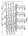
- composition example 2 of the first embodiment of the present invention will be explained referring to FIG. 9.
- the parts of this composition shared to those of the basic composition shown in FIGS. 7 and 8 are given shared numerals and symbols and the explanation thereof are omitted here.
- This example is a variation of the basic composition shown in FIG. 8.
- the output ports of the optical splitter 9 for branching the optical signal passing the second optical path 23 to a plurality of optical paths are respectively connected to the optical gates 6.
- wavelength converters 20a-20d having optical gate function respectively, are respectively connected between each pair of the wavelength multiplexer 11 and the wavelength multiplexer 12, located respectively in the stage following the each output port of the optical splitter 9, to form the multi-wavelength optical source equipment 70.
- Each of the wavelength converters 20a-20d including the optical gate function has both the optical gate function for passing or intercepting the optical signal outputted from the output port of the optical splitter 9 and the wavelength conversion function for converting the wavelength of the optical signal into a desired wavelength.
- the control information, for selecting one or plural of the optical gate(s), included in the optical signal is guided for analysis to the control system 7 through the optical receiver 5 so that the control system 7 outputs the control signal for the selection of the optical gates to the corresponding wavelength converters 20a-20d including optical gate function according to the result of the analysis.
- the electric lines for the control signal between the control system 7 and each of the wavelength converters 20a-20d including optical gate function is omitted for avoiding the complication of the diagram.
- the wavelength converter 20i (i represents any one of a, b, c and d) corresponding to the addressed communication node is selected according to the control information. And the optical signal is outputted from the output port of the selected wavelength converter 20i.
- the wavelength converters 20a-20d with the optical gate function can be used as the substitutes for the optical gates 6 and the wavelength converters 10a-10d shown in FIG. 8, so that the number of parts can be reduced further.
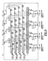
- composition example 3 of the first embodiment of the present invention will be explained referring to FIG. 10.
- the parts shared to those explained in FIGS. 8 and 9 are given shared numerals and symbols and the explanation thereof are omitted here.
- This example is a variation of the basic composition shown in FIG. 9.
- one of the wavelength converters 20a-20d having the optical gate function respectively, is interposed for connecting each pair of wavelength multiplexing path 11 and the wavelength multiplexer 12, which are located respectively in the stage following one of the output ports of the optical splitter 9 for branching the optical signal passing the second optical path 23 to a plurality of optical paths.
- each of the wavelength converters 21a-21d incorporating an optical gate is connected to the following stage of each of the output ports of each optical splitter 9 to form the multi-wavelength optical source equipment 70.
- Each of the wavelength converters 21a-21d incorporating the optical gate has both the wavelength conversion function for converting the wavelength of the optical signal outputted from the output port of the optical splitter 9 into a desired wavelength and an optical gate for passing or intercepting the optical signal in the device.
- FIG. 11 shows the internal structure of each of the wavelength converters 21a-21d incorporating an optical gate respectively.
- Numerals 301 and 302 denotes input ports of the wavelength converters 21a-21d respectively incorporating an optical gate;
- Numeral 412 an output port of the optical gate 6;
- Numeral 401 an output port of the wavelength converter incorporating an optical gate;
- Numerals 501, 502, 510 and 520 optical lines.
- the input port 301 of the wavelength converter incorporating an optical gate receives the input light from any one of the shared optical sources 8a-8d, while the input port 302 receives the optical signal that has passed the optical splitter 9.
- each of the wavelength converters 10a-10d outputs the optical signal whose wavelength has been converted into the wavelength of the shared optical source. That is, when the wavelengths of the shared optical sources 8a-8d are given as ⁇ a, ⁇ b, ⁇ c and ⁇ d, the wavelength converter 10 connected to the shared optical source 8a outputs a signal whose wavelength has been converted into the wavelength ⁇ a; the wavelength converter 10 connected to the shared optical source 8b outputs a signal whose wavelength converted into the wavelength ⁇ b: the wavelength converter 10 connected to the shared optical source 8c outputs a signal whose wavelength converted into ⁇ c; the wavelength converter 10 connected to the shared optical source 8d outputs a signal whose wavelength converted into ⁇ d.
- the control information, for selecting one or plural optical gate(s), included in the optical signal is led, through the optical receiver 5, to the control system 7 for analysis, and the control system 7 outputs the control signal for the selection of the optical gates to one of the wavelength converters incorporating optical gates 21a-21d according to the result of the analysis.
- the lines for control signal between the control system 7 and each of the wavelength converters 21a-21d incorporating an optical gate respectively is omitted for avoiding the complication of the diagram.
- the optical signal passed the optical splitter 9 is fed to the input port 302 of the wavelength converter 21 (the representative number of 21a-21d) incorporating an optical gate and outputted from the output port 401 of the wavelength converter 21 incorporating an optical gate after undergoing the wavelength conversion by the wavelength converter 10 for being output from its output port 411 and subsequent input to the optical gate 6 and passing the output port 412 of the optical gate 6 whose state is open.
- the optical signal outputted from the output port 401 passes the wavelength multiplexer 12 and routed to the destination communication node by means of the wavelength routing by the cyclic-wavelength arrayed-waveguide grating.
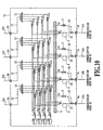
- composition example 4 of the first embodiment of the present invention will be explained referring to FIG. 12.
- the parts shared to those of the previous example are given shared numerals and symbols and the explanation thereof is omitted.
- This example is a variation of the basic composition shown in FIG. 8. That is, the multi-wavelength optical source equipment 70 incorporates the cyclic-wavelength arrayed-waveguide grating 60 as an optical component having the wavelength routing function.
- the cyclic-wavelength arrayed-waveguide grating 60 is employed as an optical component having the wavelength routing function, but the components other than this component may be used as long as the latter have the functions equivalent to that of the former.
- composition example 5 of the first embodiment of the present invention will be explained referring to FIG. 13.
- the parts shared to those of previous examples are given shared numerals and symbols and the explanation thereof are omitted.
- the principal optical signals transmitted from a communication node 30 are connected with a wavelength demultiplexer 31 for separating the principal optical signal and the control optical signals differing from the principal optical signals in wavelength instead of the optical splitter 3 in the case of the previously mentioned basic composition.
- a silica glass waveguide type wavelength demultiplexer may be employed for this wavelength demuliplexer 31.
- the rest of the composition is similar to the basic composition shown in FIG. 8.
- the operation of the multi-wavelength optical source equipment 70 will be explained. It will be explained below giving an example how the principal optical signal addressed to the communication mode #3 sent out from the communication node #1 connected to the input port 1a of the multi-wavelength optical source equipment 70 will reach the destination communication node #3.
- the principal optical signal addressed to the communication node #3 and the optical signal for control differing in wavelength from the principal optical signal are transmitted from the communication node #1 to be inputted to the input port 1a of the multi-wavelength optical source equipment 70.
- the principal optical signal fed to the input port 1a and the control signal to be used for controlling the operation of the multi-wavelength optical source equipment 70 are branched to the first optical path 22 and the second optical path 23 by means of the wavelength demultiplexer 31.
- the optical signal for control (including the control component for the selection of the optical gate) branched to the first optical path 22 is guided to the optical receiver 5 connected to the control system 7.
- the principal optical signal (including the data component) branched to the second optical path 23 is guided to the optical gate 6 through the optical fiber type optical delay device 4 and the optical splitter 9.
- the optical signal for control received by the optical receiver 5 is analyzed by the control system 7.
- the control system 7 outputs the control signal for the selection of the optical gate to the optical gates 6 according to the result of the analysis.
- the optical gate 6 is selected according to the control signal (i.e., control component for the selection of the optical gate), and the principal optical signal is outputted from the output port of the selected optical gate 6.
- the optical signal outputted from the output port of the selected optical gate 6 is inputted to the wavelength converter 10i (i is a, b, c or d) connected to the selected output port.
- the wavelength converter 10i converts the wavelength of the optical signal into the wavelength (wavelength ⁇ 13; however, ⁇ 13 is one of ⁇ 1 - ⁇ 4) adapted for the routing to the destination communication node #3 by means of the cyclic-wavelength arrayed-waveguide grating 60 having the wavelength routing function.
- the optical signal whose wavelength has been converted into the wavelength ⁇ 13 by way of the wavelength converter 10i is guided to the input port 61i (i is one of a, b, c or d) of the cyclic-wavelength arrayed-waveguide grating 60 connected to the corresponding output port 2i (i is one of a, b, c or d) of the multi-wavelength optical source equipment 70 (Refer to FIG. 7).
- the output port leading to the desired communication node 30 is selected by the wavelength routing.
- the output port connected to the communication node #3 is selected. In this way, the optical signal is routed to be received by the destination communication node #3 by the cyclic-wavelength arrayed-waveguide grating 60.
- the principal optical signal transmitted to the communication node #j from the communication node #i is converted into the desired wavelength ⁇ ij by the multi-wavelength optical source equipment 70 and routed on the basis of the converted wavelength ⁇ ij to the communication node #j by the cyclic-wavelength arrayed-waveguide grating 60.
- composition example 6 of the first embodiment of the present invention will be explained referring to FIG. 14.
- the parts shared to those of the preceding example are given shared numerals and the symbols and the explanation thereof are omitted.
- the multi-wavelength optical source equipment 70 incorporates the wavelength demultiplexer 31 for separating the principal optical signal and the optical signal for control differing in wavelength from the principal optical signal and the cyclic-wavelength arrayed- waveguide grating 60 as an optical component having the wavelength routing function.
- the cyclic-wavelength arrayed-waveguide grating 60 is employed as an optical component having the wavelength routing function, but any other component having the equivalent function may also be employed as a substitute.
- composition example 7 of the first embodiment of the present invention will be explained referring to FIG. 15.
- the parts shared to those of the previous examples are given shared numerals and symbols and the explanations thereof are omitted.
- optical transmitters 17 for transmitting the information coming from the control system 7 to each of the communication nodes 30 are provided on the side of the first optical path 22.
- the rest of the composition is similar to the aforementioned composition example 5.
- Each information of the control system 7 is transmitted, either selectively or by broadcasting, through the optical transmitter 17, to the corresponding communication nodes 30 connected to the multi-wavelength optical source equipment 70. In this way, the smooth communication among a plurality of communication nodes 30 constituting this optical network can be facilitated.
- composition example 8 of the first embodiment of the present invention will be explained referring to FIG. 16.
- the parts shared to those of the previous examples are given shared numerals and symbols and the explanations thereof are omitted.
- This example is a variation of the preceding composition example 7. More particularly, the multi-wavelength optical source equipment 70 incorporates above-mentioned optical transmitters 17 and the cyclic-wavelength arrayed-waveguide grating 60 as an optical unit having wavelength routing function.
- the cyclic-wavelength arrayed-waveguide grating 60 is employed as an optical unit having the wavelength routing function, but any other optical unit having equivalent function may be employed as a substitute.
- composition example 9 of the first embodiment of the present invention will be explained referring to FIG. 17.
- the parts shared to those of previous examples are given shared numerals and symbols and the explanations thereof are omitted.
- each of the wavelength converters 10a-10d is provided, with two input ports.
- One of the two input ports of each of the wavelength converters 10a-10d receives the light from the shared optical sources 8a-8d, while the other receives the optical signal passing the optical gate 6.
- Each of the output ports of the wavelength converters 10a-10d outputs the optical signal whose wavelength is converted into the wavelength of the shared optical source. More particularly, where the wavelengths of the shared optical sources 8a-8d are given as ⁇ a, ⁇ b, ⁇ c and ⁇ d, the optical signal whose wavelength is converted into ⁇ a is outputted from the wavelength converter 10a connected to the shared optical source 8a; the optical signal whose wavelength is converted into ⁇ b is outputted from the wavelength converter 10b connected to the shared optical source 8b; the optical signal whose wavelength is converted into ⁇ c is outputted from the wavelength converter 10c connected to the shared optical source 8c; the optical signal whose wavelength is converted into ⁇ d is outputted from the shared optical source 8d.
- the wavelength converters 10a-10d may be replaced with the wavelength converters utilizing the cross-phase modulation of the semiconductor optical amplifier, though not limited to these substitutes as long as other substitutes have equivalent functions.
- FIG. 18 is a schematic diagram illustrating the composition of the multi-wavelength optical source equipment according to the composition example 10 of the first embodiment of the present invention.
- Numerals 30a-30d denote communication nodes. (In FIG. 18, the communication node 30c is not shown, but the composition is similar to those of other communication nodes.)
- Numeral 70 denotes the multi-wavelength optical source equipment; Numerals 1a-1d, the input ports of the multi-wavelength optical source equipment 70; Numerals 2a-2d, the output ports of the multi-wavelength optical source equipment 70.
- Numerals 42a-42d denote the optical signal transmitters including the optical source and employed for transmitting the optical signal; Numerals 43a-43d, the optical label signal transmitters including the optical source and employed for transmitting the optical label signal; Numerals 46a-46e, optical receivers; Numerals 47a-47d, the optical receivers employed for receiving the optical clock signal.
- Numerals 25a-25d are the clock generator for the optical signal transmitter, which supplies the clock frequency to be used for the generation of the optical signal to the optical signal transmitter including the optical source for transmitting the optical signal;
- Numerals 26a-26d are the optical signal regenerators for regenerating the optical signals received by the optical receivers 46a-46d;
- Numerals 29a-29d are clock frequency regenerators for regenerating the clock frequency from the electric signal converted from the optical clock signal by means of the optical clock signal receivers 47a-47d.
- Numerals 28a-28d are the electric lines for supplying the clock frequency regenerated by the clock frequency regenerators 29a-29d to the clock generators 25a-25d for the optical signal transmitter and the optical signal regenerators 26a-26d.
- Numerals 45a-45d are the wavelength demultiplexers; Numeral 18, an optical combiner; Numeral 52, an optical combiner & splitting device. Numerals 14a-14d are the optical lines for connecting the optical combiner & splitting devices 52 of each communication node and the input port of the multi-wavelength optical source equipment 70; Numerals 15a-15d, the optical lines for connecting the output port of the multi-wavelength optical source equipment 70 and the wavelength demultiplexers 45a-45d of the communication nodes 30a-30d; Numerals 48a-48d, optical signals; Numerals 49a-49d, optical label signals.
- Numerals 24a-24d are the optical transmitters for distributing the reference clock frequency, which is used when each of the communication nodes 30a-30d receives and transmits the optical signal; Numeral 4, the optical delay device; Numerals 6a-6d,the optical gates; Numeral 9, the optical splitter; Numerals 8-8d, the shared optical sources; numerals 10a-10d, the wavelength converters; Numeral 11, the wavelength multiplexer; Numerals 12a-12d, the wavelength multiplexers; Numeral 27, an optical gate controller & reference clock generating system; Numerals 53a-53d, the optical combiner & splitting devices; Numeral 19, the wavelength demultiplexer and multiplexer.
- Numeral 60 denotes the cyclic-wavelength arrayed-waveguide grating; Numerals 61a-61d, the input ports of the cyclic-wavelength arrayed-waveguide grating 60; Numerals 62a-62d, the output ports of the cyclic-wavelength arrayed-waveguide grating 60.
- an optical fiber type optical combiner may be employed as the optical combiner 18; an optical fiber type demultiplexer & multiplexer, for example, as the wavelength demultiplexer & muliplexer 19; optical parts including the semiconductor optical amplifiers, for example, as the optical gates 6a-6d; a silica glass waveguide type optical splitter, for example, as the optical splitter 9; optical fibers, for example, as the optical lines 14a-14d and optical lines 15a-15d; silica glass optical waveguide type wavelength demultiplexers, for example, as the wavelength demultiplexers 45a-45d; optical fiber type optical combiner & splitting devices, for example, as the optical combiner & splitting devices 52 and 53a-53d; distributed feedback type semiconductor lasers, for example, as the shared optical sources 8a-8d; semiconductor optical amplifier type optical wavelength converters utilizing cross gain modulation, for example, as the wavelength converters 10a-10d; silica glass optical waveguide type wavelength multiplexers, for example, as the wavelength multiplex
- the wavelengths of the shared optical sources 8a, 8b, 8c and 8d are ⁇ a, ⁇ b, ⁇ c and ⁇ d respectively.
- the wavelength converters 10a, 10b, 10c and 10d respectively receive the lights having wavelengths ⁇ a, ⁇ b, ⁇ c and ⁇ d respectively, and respectively convert the wavelengths of the optical signals transmitted passing the optical gates 6a-6d respectively connected to the input ports of the optical wavelength converters l0a-lOd to the wavelengths of the shared optical sources. More articularly, the wavelength of the optical signal that has passed the optical gate 6a is converted into the wavelength ⁇ a by the wavelength converter 10a and outputted from the output port of the wavelength converter 10a.
- the wavelength of the optical signal that has passed the optical gate 6b is converted into the wavelength ⁇ b by the wavelength converter 10b and outputted from the output port of the wavelength converter 10b.
- the wavelength of the optical signal that has passed the optical gate 6c is converted into the wavelength ⁇ c by the wavelength converter 10c and outputted from the output port of the wavelength converter 10c.
- the wavelength of the optical signal that has passed the optical gate 6d is converted into wavelength ⁇ d by the wavelength converter 10d and outputted form the output port of the wavelength converter 10d.
- FIG. 21 shows the relationship of the input and output wavelengths by each port of the cyclic-wavelength arrayed-waveguide grating 60.
- the wavelength routing characteristic of the cyclic-wavelength arrayed-waveguide grating 60 will be explained referring to FIG. 21.
- ⁇ a is outputted from the output port 62a, ⁇ b from the output port 62b, ⁇ c from the output port 62c and ⁇ d from the output port 62d as shown in FIG. 21.
- the lights respectively having the wavelengths ⁇ a, ⁇ b, ⁇ c and ⁇ d are fed to each of the input ports 61b-61d, according to the rule shown in FIG. 21, the lights respectively having the wavelengths ⁇ a, ⁇ b, ⁇ c and ⁇ d are outputted respectively from the output ports 62a-62d.
- the wavelength demultiplexers 45a-45d of the communication nodes 30a-30d respectively have a function of demultiplexing the lights having the wavelengths ⁇ a, ⁇ b, ⁇ c and ⁇ d incoming to input port 200 to different output ports 201a-201d respectively as shown in FIG. 22.
- the optical signal 48a and the optical label signal 49a sent out from the communication node 30a to the communication node 30d passes the optical combiner 18 and optical combiner & splitting device 52 to be fed to the input port 1a of the multi-wavelength optical source equipment 70.
- optical signal 48a and the optical label signal 49a respectively fed to the input port 1a of the multi-wavelength optical source equipment 70 is separated for the first optical path connected to the optical combiner & splitting device 53and the second optical path connected to the optical delay device 4.
- the optical label signal 49a branched to the first optical path is guided to the optical receiver 46e through the optical combiner & splitting device 53a.
- the optical receiver 46e is connected to the optical gate controller & reference clock frequency supply system 27.
- the optical signal 48a branched to the second optical path is guided to a plurality of optical gates 6a-6d respectively through the optical delay device 4 and the optical splitter 9.
- the optical signal 48a fed to the optical gates 6a-6d is outputted from the optical gate 6i (i denotes any of a, b, c and d) selected according to the information of the optical label signal 49a previously received by the optical receiver 46e by the optical gate controller & reference clock frequency supply system 27.
- the optical gates 6a-6d are controlled by the optical gate controller & reference clock frequency supply system 27.
- the optical gate 6i is connected to the wavelength converter 10j (j denotes any of a, b, c and d) which converts the wavelength of the optical signal 48a into the wavelength adapted for routing to the communication node 30d by using the cyclic-wavelength arrayed-waveguide grating 60 having the wavelength routing function.
- the output ports of the optical gates 6a-6d are respectively connected to the input port 61a of the cyclic-wavelength arrayed-waveguide grating 60 through the wavelength multiplexer 11, wavelength converters 10a-10d and wavelength multiplexer 12, so that the optical signal having wavelength ⁇ d is routed to the communication node 30d by the cyclic-wavelength arrayed-waveguide grating 60 as shown in FIG.21. Therefore, the optical gate 6d, connected to the wavelength converter 10d for converting the wavelength of the optical signal 48a into the wavelength ⁇ d, is activated for passing the optical signal 48a according to the control signal from the optical gate controller and reference clock frequency supply system 27.
- the optical signal 48a outputted from the optical gate 6d is fed to the wavelength converter 10d connected with the output port of the optical gate to have its wavelength converted into ⁇ d and introduced to the input port 61a of the cyclic-wavelength arrayed-waveguide grating 60 through the wavelength multiplexer 12a.
- the optical signal 48a introduced to the input port 61a having wavelength ⁇ d, is outputted from the output port 62d of the cyclic-wavelength arrayed-waveguide grating 60 connected to the communication node 30d by the wavelength routing function of the cyclic-wavelength arrayed-waveguide grating 60 shown in FIG. 21.
- the optical signal 48a outputted from the output port 62d of the cyclic-wavelength arrayed-waveguide grating 60 passes the output port 2d of the multi-wavelength optical source equipment 70 and the optical line 15d to arrive at the input port of the wavelength demultiplexer 45d on the side of the communication node 30d. Since the wavelength demultiplexers 45a-45d employed in this example have the output characteristic shown in FIG. 22, the optical signal 48a is outputted from the output port 201d of the wavelength demultiplexer 45d to be received by the optical receiver 46d.
- the optical signal 48i (i denotes any of a, b, c and d) transmitted from any given communication node 30i (i denotes any of a, b, c and d) to any given communication node 30j (j denotes any of a, b, c and d) is routed by the multi-wavelength optical source equipment 70 to the communication node 30j (j denotes any of a, b, c and d).
- the multi-wavelength optical source equipment 70 in the case of this example is provided with the optical transmitters 24a-24d for employed distributing the reference clock frequency, and these optical transmitters transmit the optical signal containing the reference frequency for the clock frequency to be used by each of the communication nodes 30a-30d in transmitting the optical signals 48a-48d and receiving the optical signal.
- the optical clock signal having the frequency component fcn is that when the optical clock signal is converted to an electrical signal by the optical receiver, the electrical signal includes the fcn frequency component. All the optical transmitters 24a-24d, for the distribution of the reference clock frequency, transmit identical optical clock signals.
- optical clock signals transmitted from the optical transmitters 24a-24d for the distribution of the reference clock frequency, pass the optical combiner & splitting devices 53a-53d, the wavelength demultiplexer & multiplexer 19 and the optical line 14 and branched by the optical combiner & splitting device 52 to be received by the optical receivers 47a-47d for receiving the optical clock signal of each of the communication nodes 30a-30d.
- the optical clock signal received by the optical receivers 47a-47d for receiving the optical clock signal is converted into an electric signal, and the electric signal is used to regenerate the clock frequency fcn from the electric signal by means of the clock frequency regenerators 29a-29d; the clock frequency fcn is supplied to each of the clock suppliers for employed transmitting the optical signal 25a-25d and each of the optical signal regenerators 26a-26d through the electric line 28.
- Each of the clock suppliers 25a-25d supplies the clock frequency fcn, which is used when each of the optical signal transmitters 42a-42d, respectively including the optical source for the transmission of the optical signal, transmits each of the optical signals 48a-48d, while each of the optical signal regenerators 26a-26d regenerates the optical signal received by each of the optical receivers 46a-46d by using the clock frequency fcn.
- each of the optical signal transmitters 42a-42d each including an optical source for transmitting the optical signal, transmits optical signals 48a-48d by using the clock frequency fcn, serving as the reference clock supplied from the multi-wavelength optical source equipment 70, while, in each of the optical signal regenerators 26a-26d for regenerating the optical signal received by each of the optical receivers 46a-46d, the clock frequency fcn is used as the clock frequency when regenerating the optical signal.
- optical transmitters of each communication node transmit the optical signals 48a-48d on the basis of a shared clock frequency.
- the regeneration of the optical signals 48a-48d to be transmitted and received among individual communication nodes can be made easier.
- composition example 11 of the first embodiment of the present invention will be explained referring to FIG. 19.
- the parts shared to those in the cases of the previous composition examples are given shared numerals and symbols and the explanations thereof are omitted.
- composition example is a variation of previously described composition example 10. More particularly, in the case of the composition example 10 shown in FIG. 18, each of the communication nodes 30a-30d is provided with a plurality of optical transmitters 24a-24d for the distribution of the reference clock frequency. In contrast, in the case of the present example, the a plurality of the optical transmitters above-mentioned for the distribution of the reference clock frequency are replaced with a single optical transmitter 24 for the distribution of the reference clock frequency as shown in FIG. 19.
- the optical clock signal having the frequency serving as the reference clock frequency for the clock frequency which is used by each of the communication nodes 30a-30d when transmitting the optical signals 48a-48d and receiving the optical signals can be provided by a single optical transmitter 24 for the distribution of the reference clock frequency and distributed by the optical splitter 9 to be transmitted to each of the communication nodes 30a-30d through the optical combiner & splitting devices 53a-53d.
- composition example 12 of the first embodiment of the present invention will be explained referring to FIG. 20.
- the parts shared to those of the composition example 11 are given shared numerals and symbols and the explanations thereof are omitted.
- This example is a variation of previous composition example 11. That is, in the case of this example, the optical clock signal having a frequency serving as reference clock frequency for the clock frequency, which is used when each of the communication nodes 30a-30d transmits the optical signals 48a-48d and receiving the optical signals, can be transmitted from a single optical transmitter 24 for the distribution of the reference clock frequency, of the multi-wavelength optical source equipment 70.
- the optical clock signal transmitted from the optical transmitter 24 for the distribution of the reference clock frequency is distributed by the optical splitter 9 and passes the optical combiners 55a-55d for combining the optical signal and the optical clock signal, the output ports 2a-2d, the optical lines 15a-15d and the wavelength demultiplexers 54a-54d to be received by the optical receivers 47a-47d employed for receiving the optical clock signal in each of the communication nodes 30a-30d.
Landscapes
- Engineering & Computer Science (AREA)
- Computer Networks & Wireless Communication (AREA)
- Physics & Mathematics (AREA)
- Electromagnetism (AREA)
- Signal Processing (AREA)
- Computing Systems (AREA)
- Optical Communication System (AREA)
- Data Exchanges In Wide-Area Networks (AREA)
Claims (13)
- Equipement formant source optique multi-longueurs d'onde pour un système de réseau optique ayant plusieurs noeuds de communication (30a - 30d) connectés entre eux par un procédé de routage en longueur d'onde, destiné à convertir la longueur d'onde des signaux optiques en longueurs d'onde souhaitées pour leur transmission à des noeuds de communication souhaités (30a - 30d), les signaux optiques transportant les informations de commande concernant le routage des signaux optiques depuis chacun des noeuds de communication (30a - 30d), comprenant :des premiers répartiteurs optiques (3) pour aiguiller les signaux optiques transmis par chacun des noeuds de communication (30a - 30d) vers un premier chemin optique (22) et un deuxième chemin optique (23) ;des récepteurs optiques (5) pour recevoir les signaux optiques qui ont suivi le premier chemin optique (22) ;des deuxièmes répartiteurs optiques (9) pour aiguiller les signaux optiques qui ont suivi le deuxième chemin optique (23) vers une pluralité de chemins optiques ;plusieurs portes optiques (6, 6a - 6d) pour laisser passer ou intercepter les signaux optiques aiguillés par les deuxièmes répartiteurs (9) ;des convertisseurs de longueur d'onde (10a - 10d) pour convertir la longueur d'onde des signaux optiques sortant des portes optiques (6, 6a - 6d) en longueurs d'onde souhaitées ;un contrôleur (7) pour commander les portes optiques (6, 6a - 6d) en fonction des informations de commande concernant le routage des signaux optiques reçus par les récepteurs optiques (5) ;des retardateurs optiques (4) pour ajuster la longueur du chemin optique de telle sorte que les signaux optiques qui ont suivi le deuxième chemin optique (22) ne pénètrent pas dans les portes optiques (6, 6a - 6d) avant que les portes optiques aient été activées par le contrôleur (7) ;des sources optiques multi-longueurs d'onde (8a - 8d) pour envoyer une lumière ayant une longueur d'onde souhaitée à chacun des convertisseurs de longueur d'onde (10a - 10d) ; etdes multiplexeurs en longueur d'onde (12) pour multiplexer les signaux optiques dont la longueur d'onde a été convertie par les convertisseurs de longueur d'onde (10a - 10d).
- Equipement formant source optique multi-longueurs d'onde selon la revendication 1, caractérisé en ce que les signaux optiques transmis par chacun des noeuds de communication (30a - 30d) comprennent un signal optique principal et un signal optique de commande transportant les informations concernant les informations de routage du signal optique principal et ayant une longueur d'onde différente de celle du signal optique principal, et le premier répartiteur optique (3) aiguille le signal optique principal vers le deuxième chemin optique et le signal optique de commande vers le premier chemin optique (22).
- Equipement formant source optique multi-longueurs d'onde selon la revendication 1, caractérisé en ce que les différentes portes optiques (6, 6a - 6d) et les convertisseurs de longueur d'onde (10a - 10d) commutent la position de connexion vers le deuxième répartiteur optique (9), de telle sorte que les convertisseurs de longueur d'onde (20a - 20d) convertissent la longueur d'onde du signal optique aiguillé par le deuxième répartiteur optique (9) en longueurs d'onde souhaitées, puis les portes optiques (20a - 20d) laissent passer ou interceptent le signal optique dont la longueur d'onde a été convertie en longueurs d'onde souhaitées pour son émission par les convertisseur de longueur d'onde (10a - 10d).
- Equipement formant source optique multi-longueurs d'onde selon la revendication 1, caractérisé en ce que chacun des noeuds de communication (30a - 30d) transmet des signaux optiques principaux et des signaux optiques de commande transportant les informations de commande concernant les informations de routage des signaux optiques principaux et ayant des longueurs d'onde différentes de celles des signaux optiques principaux, et les convertisseurs de longueur d'onde (10a - 10d) et les portes optiques (6, 6a - 6d) sont remplacés par des convertisseurs de longueur d'onde (10a - 10d) ayant la fonction de conversion de longueur d'onde pour convertir la longueur d'onde des signaux optiques principaux qui ont suivi le deuxième chemin optique (23) en la longueur d'onde souhaitée, ainsi que la fonction de porte optique pour laisser passer ou intercepter les signaux optiques principaux.
- Equipement formant source optique multi-longueurs d'onde selon la revendication 1, caractérisé en ce que l'équipement formant source optique multi-longueurs d'onde comprend, en outre, des transmetteurs optiques (40) pour transmettre les informations de commande depuis le contrôleur (7) vers les noeuds de communication (30a - 30d) qui ont transmis les signaux optiques à travers les premiers répartiteurs optiques (3).
- Equipement formant source optique multi-longueurs d'onde selon la revendication 3, caractérisé en ce que l'équipement formant source optique multi-longueurs d'onde comprend, en outre, des transmetteurs optiques (24a-24d) pour transmettre les informations de commande depuis le contrôleur (7) vers les noeuds de communication (30a - 30d) qui ont transmis les signaux optiques à travers les premiers répartiteurs optiques (3).
- Equipement formant source optique multi-longueurs d'onde selon la revendication 1, caractérisé en ce que l'équipement formant source optique multi-longueurs d'onde comprend des moyens de génération de fréquence d'horloge de référence (24) pour fournir la fréquence d'horloge de référence à utiliser pour la transmission des signaux optiques et la régénération des signaux optiques reçus dans chacun des noeuds de communication (30a - 30d), et des moyens de distribution de fréquence d'horloge de référence pour distribuer ladite fréquence d'horloge de référence parmi les noeuds de communication (30a - 30d).
- Equipement formant source optique multi-longueurs d'onde selon la revendication 3, caractérisé en ce que l'équipement formant source optique multi-longueurs d'onde comprend des moyens de génération de fréquence d'horloge de référence (25) pour fournir la fréquence d'horloge de référence à utiliser pour la transmission des signaux optiques et la régénération des signaux optiques reçus dans chacun des noeuds de communication (30a - 30d), et des moyens de distribution de fréquence d'horloge de référence pour distribuer ladite fréquence d'horloge de référence parmi les noeuds de communication (30a - 30d).
- Equipement formant source optique multi-longueurs d'onde selon la revendication 1, caractérisé en ce que plusieurs ports de sortie (2a - 2d) de l'équipement formant source optique multi-longueurs d'onde sont connectés aux ports d'entrée (61a - 61d) correspondants du dispositif optique ayant la fonction de routage en longueur d'onde.
- Equipement formant source optique multi-longueurs d'onde selon la revendication 1, caractérisé en ce que l'équipement formant source optique multi-longueurs d'onde comprend un dispositif optique ayant une fonction de routage en longueur d'onde, et le dispositif optique est connecté à un étage situé après les multiplexeurs en longueur d'onde (12).
- Equipement formant source optique multi-longueurs d'onde selon la revendication 9, caractérisé en ce qu'un réseau de guide d'onde à longueurs d'onde cycliques (60) est utilisé en tant que dispositif optique ayant la fonction de routage.
- Equipement formant source optique multi-longueurs d'onde selon la revendication 10, caractérisé en ce qu'un réseau de guide d'onde à longueurs d'onde cycliques (60) est utilisé en tant que dispositif optique ayant la fonction de routage.
- Equipement formant source optique multi-longueurs d'onde selon la revendication 1, caractérisé en ce que des éléments amplificateurs optiques à semi-conducteurs sont utilisés en tant que convertisseurs de longueur d'onde (10a - 10d).
Priority Applications (1)
| Application Number | Priority Date | Filing Date | Title |
|---|---|---|---|
| EP04077739A EP1499077B1 (fr) | 1999-08-25 | 2000-08-25 | Routage optique de paquets dans un système de réseau basé sur une technique de commutation d'étiquettes optiques |
Applications Claiming Priority (4)
| Application Number | Priority Date | Filing Date | Title |
|---|---|---|---|
| JP23879499 | 1999-08-25 | ||
| JP23879499 | 1999-08-25 | ||
| JP2000070872 | 2000-03-14 | ||
| JP2000070872 | 2000-03-14 |
Related Child Applications (2)
| Application Number | Title | Priority Date | Filing Date |
|---|---|---|---|
| EP04077739A Division EP1499077B1 (fr) | 1999-08-25 | 2000-08-25 | Routage optique de paquets dans un système de réseau basé sur une technique de commutation d'étiquettes optiques |
| EP04077739.3 Division-Into | 2004-10-08 |
Publications (4)
| Publication Number | Publication Date |
|---|---|
| EP1079571A2 EP1079571A2 (fr) | 2001-02-28 |
| EP1079571A3 EP1079571A3 (fr) | 2004-03-24 |
| EP1079571B1 true EP1079571B1 (fr) | 2006-10-04 |
| EP1079571B8 EP1079571B8 (fr) | 2008-08-13 |
Family
ID=26533899
Family Applications (2)
| Application Number | Title | Priority Date | Filing Date |
|---|---|---|---|
| EP04077739A Expired - Lifetime EP1499077B1 (fr) | 1999-08-25 | 2000-08-25 | Routage optique de paquets dans un système de réseau basé sur une technique de commutation d'étiquettes optiques |
| EP00307358A Expired - Lifetime EP1079571B8 (fr) | 1999-08-25 | 2000-08-25 | Routage optique de pacquets dans un système de réseau basé sur une technique de commutation d'étiquettes optiques |
Family Applications Before (1)
| Application Number | Title | Priority Date | Filing Date |
|---|---|---|---|
| EP04077739A Expired - Lifetime EP1499077B1 (fr) | 1999-08-25 | 2000-08-25 | Routage optique de paquets dans un système de réseau basé sur une technique de commutation d'étiquettes optiques |
Country Status (5)
| Country | Link |
|---|---|
| US (3) | US6782210B1 (fr) |
| EP (2) | EP1499077B1 (fr) |
| KR (1) | KR100351085B1 (fr) |
| CA (1) | CA2316621C (fr) |
| DE (1) | DE60031055T2 (fr) |
Families Citing this family (35)
| Publication number | Priority date | Publication date | Assignee | Title |
|---|---|---|---|---|
| DE10131210B4 (de) * | 2001-06-28 | 2006-04-20 | Siemens Ag | Optisches Übertragungssystem mit bidirektionalen Verbindungspfaden und Verfahren zum Einrichten mindestens eines bidirektionalen Verbindungspfades |
| FR2832571B1 (fr) * | 2001-11-22 | 2004-04-16 | Cit Alcatel | Systeme de transmission par fibres optiques a horloge commune |
| WO2004070978A2 (fr) * | 2003-01-29 | 2004-08-19 | Yissum Research Development Company Of The Hebrew University Of Jerusalem | Reseau d'alimentation laser |
| US7298974B2 (en) * | 2003-02-13 | 2007-11-20 | Nippon Telegraph And Telephone Corporation | Optical communication network system |
| JP4291281B2 (ja) * | 2005-02-03 | 2009-07-08 | 富士通株式会社 | 情報処理システム、計算ノード、情報処理システムの制御方法 |
| US7706685B2 (en) * | 2005-09-20 | 2010-04-27 | Lockheed Martin Corporation | Data communication network using optical power averaged multiplexing |
| US20090123147A1 (en) * | 2007-11-14 | 2009-05-14 | Acterna Llc | Test Instrument For Testing Multi-Wavelength Optical Networks Using Two Or More Tunable Lasers |
| US8687630B2 (en) * | 2008-06-05 | 2014-04-01 | Metis Secure Solutions, Llc | Emergency alerting device |
| KR101257070B1 (ko) * | 2009-09-01 | 2013-04-22 | 한국전자통신연구원 | 노드 장치 및 그의 광 신호 수신 방법과 링 네트워크 시스템 |
| JP5491810B2 (ja) * | 2009-09-25 | 2014-05-14 | パナソニック株式会社 | 放電灯点灯装置及び照明器具 |
| US9607412B2 (en) * | 2010-02-04 | 2017-03-28 | Ciena Corporation | Method for rapid determination of lowest cost wavelength routes through a photonic network based on pre-validated paths |
| US8965203B1 (en) * | 2012-01-09 | 2015-02-24 | Google Inc. | Flexible non-modular data center with reconfigurable extended-reach optical network fabric |
| US10194222B2 (en) | 2016-10-17 | 2019-01-29 | Electronics And Telecommunications Research Institute | Packet-based optical signal switching control method and apparatus |
| JP6830790B2 (ja) | 2016-10-26 | 2021-02-17 | 技術研究組合光電子融合基盤技術研究所 | ネットワークシステム |
| WO2018183542A1 (fr) | 2017-03-29 | 2018-10-04 | Fungible, Inc. | Réseau de centre de données sans contraintes sans blocage avec pulvérisation de paquets sur de multiples chemins de données alternatifs |
| WO2018183526A1 (fr) | 2017-03-29 | 2018-10-04 | Fungible, Inc. | Réseau de centre de données à maillage complet, sans blocage et ayant des dispositifs de permutation optique |
| WO2018183553A1 (fr) * | 2017-03-29 | 2018-10-04 | Fungible, Inc. | Réseau de centre de traitement de données à connectivité complète sans blocage présentant une pulvérisation de paquets multiplexée dans des groupes de nœuds d'accès |
| CN117971715A (zh) | 2017-04-10 | 2024-05-03 | 微软技术许可有限责任公司 | 多处理器系统中的中继一致存储器管理 |
| US10659254B2 (en) | 2017-07-10 | 2020-05-19 | Fungible, Inc. | Access node integrated circuit for data centers which includes a networking unit, a plurality of host units, processing clusters, a data network fabric, and a control network fabric |
| CN117348976A (zh) | 2017-07-10 | 2024-01-05 | 微软技术许可有限责任公司 | 用于流处理的数据处理单元 |
| CN107634920B (zh) * | 2017-08-31 | 2020-02-21 | 华为技术有限公司 | 一种数据传输系统 |
| US10965586B2 (en) | 2017-09-29 | 2021-03-30 | Fungible, Inc. | Resilient network communication using selective multipath packet flow spraying |
| US12278763B2 (en) | 2017-09-29 | 2025-04-15 | Microsoft Technology Licensing, Llc | Fabric control protocol with congestion control for data center networks |
| US12212495B2 (en) | 2017-09-29 | 2025-01-28 | Microsoft Technology Licensing, Llc | Reliable fabric control protocol extensions for data center networks with unsolicited packet spraying over multiple alternate data paths |
| US12231353B2 (en) | 2017-09-29 | 2025-02-18 | Microsoft Technology Licensing, Llc | Fabric control protocol for data center networks with packet spraying over multiple alternate data paths |
| US12294470B2 (en) | 2017-09-29 | 2025-05-06 | Microsoft Technology Licensing, Llc | Fabric control protocol for large-scale multi-stage data center networks |
| US12341687B2 (en) | 2017-09-29 | 2025-06-24 | Microsoft Technology Licensing, Llc | Reliable fabric control protocol extensions for data center networks with failure resilience |
| US11178262B2 (en) | 2017-09-29 | 2021-11-16 | Fungible, Inc. | Fabric control protocol for data center networks with packet spraying over multiple alternate data paths |
| WO2019104090A1 (fr) | 2017-11-21 | 2019-05-31 | Fungible, Inc. | Structures de données d'empilement d'unités de travail dans un système de processeur multicœur pour traitement de données de flux |
| WO2019152063A1 (fr) | 2018-02-02 | 2019-08-08 | Fungible, Inc. | Traitement efficace d'unité de travail dans un système multicœur |
| US10929175B2 (en) | 2018-11-21 | 2021-02-23 | Fungible, Inc. | Service chaining hardware accelerators within a data stream processing integrated circuit |
| US11589140B2 (en) * | 2020-06-08 | 2023-02-21 | Electronics And Telecommunications Research Institute | Optical beamforming device using phased array antenna and operating method thereof |
| CN112291016B (zh) * | 2020-10-30 | 2021-09-17 | 台州科技职业学院 | 非正交调制下的伪正交线路编码实现标签信号调制方法 |
| CN115580344A (zh) * | 2021-06-21 | 2023-01-06 | 华为技术有限公司 | 通信系统、发射机及通信方法 |
| EP4178132B1 (fr) * | 2021-11-03 | 2024-01-10 | Deutsche Telekom AG | Procédé pour établir ou commuter un chemin de transmission optique afin de transmettre un signal optique, noeud de réseau optique pour établir ou commuter un chemin de transmission optique afin de transmettre un signal optique, réseau dorsal, réseau d'agrégation ou réseau de télécommunications, système, programme et support lisible par ordinateur |
Family Cites Families (27)
| Publication number | Priority date | Publication date | Assignee | Title |
|---|---|---|---|---|
| JPH0247984B2 (ja) | 1982-08-24 | 1990-10-23 | Chisso Corp | Toransuu44arukiruutoransuu4****44harogenobenzoiruokishi**okutadekahidorootoransuuppterufueniru |
| DE3689583T2 (de) | 1985-11-22 | 1994-08-25 | Nippon Electric Co | Optisches Wellenlängenmultiplexvermittlungssystem mit Wellenlängenschaltlichtmodulatoren. |
| JPS636993A (ja) | 1986-06-27 | 1988-01-12 | Hitachi Ltd | 波長分割形光交換方式 |
| JPH0787624B2 (ja) | 1987-11-11 | 1995-09-20 | 沖電気工業株式会社 | 光波長多重自己ルーチングスイッチ |
| JPH01127707A (ja) | 1987-11-11 | 1989-05-19 | Sumitomo Electric Ind Ltd | 可撓性膜製起伏堰を起立させる方法 |
| GB8902745D0 (en) | 1989-02-08 | 1989-03-30 | British Telecomm | Optical interconnection network |
| DE4019225A1 (de) | 1990-06-15 | 1991-12-19 | Standard Elektrik Lorenz Ag | Optisches schaltelement |
| CA2055546C (fr) * | 1990-11-14 | 1999-02-02 | Shuji Suzuki | Reseau a acheminement automatique utilisant des circuits optiques prediffuses commandes par des tensions coincidant avec les impulsions d'en-tete de paquet |
| CA2284243C (fr) | 1991-01-10 | 2000-12-12 | Fujitsu Limited | Dispositif de traitement optique a controle de longueur d'onde synchronisee et changeur de circuits optique utilisant ce dispositif |
| FR2672173B1 (fr) * | 1991-01-29 | 1993-09-03 | Cit Alcatel | Multiplexeur temporel photonique, et demultiplexeur temporel photonique. |
| US5253250A (en) | 1991-12-31 | 1993-10-12 | Gte Laboratories Incorporated | Routing and switching of high-speed optical data with the header transmitted on a subcarrier frequency |
| GB9207937D0 (en) | 1992-04-09 | 1992-05-27 | British Telecomm | Optical processing system |
| SG48849A1 (en) | 1992-04-09 | 1998-05-18 | British Telecomm | Optical processing system |
| JP3283601B2 (ja) | 1993-01-13 | 2002-05-20 | 沖電気工業株式会社 | 自己ルーチングの方法、その装置及びパケット構造 |
| JP2713324B2 (ja) | 1993-02-02 | 1998-02-16 | 日本電信電話株式会社 | 光波アドレスシステム |
| JPH06235946A (ja) | 1993-02-10 | 1994-08-23 | Fujitsu Ltd | 光セルフルーチングスイッチ |
| US5367586A (en) | 1993-03-26 | 1994-11-22 | At&T Bell Laboratories | Optical delay line |
| FR2709839B1 (fr) | 1993-09-10 | 1995-12-01 | Slimane Loualiche | Commutateur de signaux optiques. |
| FR2726726A1 (fr) * | 1994-11-04 | 1996-05-10 | Guillemot Christian | Systeme de commutateur pour paquets optiques |
| JP3201566B2 (ja) | 1995-01-17 | 2001-08-20 | 日本電信電話株式会社 | 光多重分離回路 |
| JP3534473B2 (ja) | 1995-02-28 | 2004-06-07 | 富士通株式会社 | 光バッファメモリ |
| JP2833536B2 (ja) | 1995-09-06 | 1998-12-09 | 日本電気株式会社 | 光バスおよび光バス構成素子 |
| US5617233A (en) * | 1995-09-28 | 1997-04-01 | The United States Of America As Represented By The Secretary Of The Air Force | Transparent optical node structure |
| FR2754352B1 (fr) * | 1996-10-07 | 1998-11-13 | Alsthom Cge Alcatel | Commutateur optique |
| JP3114801B2 (ja) | 1997-07-07 | 2000-12-04 | 日本電気株式会社 | 光通信ネットワーク装置 |
| KR100265792B1 (ko) * | 1997-09-26 | 2000-09-15 | 윤종용 | 파장분할다중전송시스템및그전송방법 |
| US6512612B1 (en) * | 1999-06-25 | 2003-01-28 | Lucent Technologies Inc. | Intelligent optical router |
-
2000
- 2000-08-23 US US09/644,324 patent/US6782210B1/en not_active Expired - Fee Related
- 2000-08-24 CA CA002316621A patent/CA2316621C/fr not_active Expired - Fee Related
- 2000-08-25 EP EP04077739A patent/EP1499077B1/fr not_active Expired - Lifetime
- 2000-08-25 DE DE60031055T patent/DE60031055T2/de not_active Expired - Lifetime
- 2000-08-25 EP EP00307358A patent/EP1079571B8/fr not_active Expired - Lifetime
- 2000-08-25 KR KR1020000049516A patent/KR100351085B1/ko not_active Expired - Fee Related
-
2004
- 2004-01-13 US US10/756,062 patent/US7113701B2/en not_active Expired - Fee Related
- 2004-01-13 US US10/756,561 patent/US7120358B2/en not_active Expired - Fee Related
Also Published As
| Publication number | Publication date |
|---|---|
| EP1079571A3 (fr) | 2004-03-24 |
| CA2316621C (fr) | 2006-03-14 |
| KR20010039841A (ko) | 2001-05-15 |
| EP1499077A1 (fr) | 2005-01-19 |
| EP1499077B1 (fr) | 2012-03-07 |
| US6782210B1 (en) | 2004-08-24 |
| EP1079571A2 (fr) | 2001-02-28 |
| US20040146300A1 (en) | 2004-07-29 |
| KR100351085B1 (ko) | 2002-09-05 |
| DE60031055T2 (de) | 2007-04-05 |
| DE60031055D1 (de) | 2006-11-16 |
| US7113701B2 (en) | 2006-09-26 |
| CA2316621A1 (fr) | 2001-02-25 |
| EP1079571B8 (fr) | 2008-08-13 |
| US20040141743A1 (en) | 2004-07-22 |
| US7120358B2 (en) | 2006-10-10 |
Similar Documents
| Publication | Publication Date | Title |
|---|---|---|
| EP1079571B1 (fr) | Routage optique de pacquets dans un système de réseau basé sur une technique de commutation d'étiquettes optiques | |
| US5550818A (en) | System for wavelength division multiplexing/asynchronous transfer mode switching for network communication | |
| EP0400959B1 (fr) | Système de réseau de communication d'information à large bande avec lignes de transmissions de données cohérentes optiques | |
| US6069719A (en) | Dynamically reconfigurable optical add-drop multiplexers for WDM optical communication systems | |
| EP2392089B1 (fr) | Noeud de réseau de communication optique et procédé de commande de transmission de données entre des n uds de réseau de communication optique | |
| JP3068018B2 (ja) | 光波長分割多重リングシステム | |
| EP1652328B1 (fr) | Utilisation de la polarisation pour differencier des informations | |
| US5712932A (en) | Dynamically reconfigurable WDM optical communication systems with optical routing systems | |
| EP1162855B1 (fr) | Réseau optique à multiplexage en longueur d'onde avec une combinaison de routage par longeurs d'onde et de routage de fibres optiques | |
| EP1161014A1 (fr) | Réseau optique autoprotégé en anneau | |
| JPH10271071A (ja) | 光通信システム | |
| US6816680B2 (en) | Optical communications network and nodes for forming such a network | |
| EP1408715B1 (fr) | Système de commutation optique à multiplexage en longueur d'onde | |
| CN100492957C (zh) | 光信号转换设备、光通信网及它们的使用方法 | |
| US7369772B2 (en) | Optical line terminal arrangement, apparatus and methods | |
| US6574386B1 (en) | Dynamically reconfigurable optical switching system | |
| EP1043847B1 (fr) | Dispositif de reseau de transmission multiplexée en longueurs d'ondes utilisant un émetteur-récepteur avec un commutateur optique à 2 entrées et 2 sorties | |
| JP3574754B2 (ja) | 光パスクロスコネクト装置 | |
| JP3292843B2 (ja) | 光波長分割多重伝送ネットワーク装置 | |
| CN100584101C (zh) | 光交换站和用于该交换站的交换方法 | |
| CA2499224C (fr) | Systeme de reseau optique de routage de paquets base sur une technique de communication optique d'etiquettes | |
| JP2006060734A (ja) | 光伝送システム | |
| WO2025094243A1 (fr) | Système de communication optique, dispositif de communication optique et procédé de communication optique | |
| JP2011172024A (ja) | 光通信装置 |
Legal Events
| Date | Code | Title | Description |
|---|---|---|---|
| PUAI | Public reference made under article 153(3) epc to a published international application that has entered the european phase |
Free format text: ORIGINAL CODE: 0009012 |
|
| 17P | Request for examination filed |
Effective date: 20000904 |
|
| AK | Designated contracting states |
Kind code of ref document: A2 Designated state(s): AT BE CH CY DE DK ES FI FR GB GR IE IT LI LU MC NL PT SE |
|
| AX | Request for extension of the european patent |
Free format text: AL;LT;LV;MK;RO;SI |
|
| RIN1 | Information on inventor provided before grant (corrected) |
Inventor name: OKADA, AKIRA Inventor name: KATO, KAZUTOSHI C/O NTT INTELL.PROPERTY CENTER |
|
| PUAL | Search report despatched |
Free format text: ORIGINAL CODE: 0009013 |
|
| AK | Designated contracting states |
Kind code of ref document: A3 Designated state(s): AT BE CH CY DE DK ES FI FR GB GR IE IT LI LU MC NL PT SE |
|
| AX | Request for extension of the european patent |
Extension state: AL LT LV MK RO SI |
|
| 17Q | First examination report despatched |
Effective date: 20040609 |
|
| AKX | Designation fees paid |
Designated state(s): DE FR GB IT |
|
| GRAP | Despatch of communication of intention to grant a patent |
Free format text: ORIGINAL CODE: EPIDOSNIGR1 |
|
| GRAS | Grant fee paid |
Free format text: ORIGINAL CODE: EPIDOSNIGR3 |
|
| GRAA | (expected) grant |
Free format text: ORIGINAL CODE: 0009210 |
|
| AK | Designated contracting states |
Kind code of ref document: B1 Designated state(s): DE FR GB IT |
|
| PG25 | Lapsed in a contracting state [announced via postgrant information from national office to epo] |
Ref country code: IT Free format text: LAPSE BECAUSE OF FAILURE TO SUBMIT A TRANSLATION OF THE DESCRIPTION OR TO PAY THE FEE WITHIN THE PRESCRIBED TIME-LIMIT;WARNING: LAPSES OF ITALIAN PATENTS WITH EFFECTIVE DATE BEFORE 2007 MAY HAVE OCCURRED AT ANY TIME BEFORE 2007. THE CORRECT EFFECTIVE DATE MAY BE DIFFERENT FROM THE ONE RECORDED. Effective date: 20061004 |
|
| REG | Reference to a national code |
Ref country code: GB Ref legal event code: FG4D |
|
| REF | Corresponds to: |
Ref document number: 60031055 Country of ref document: DE Date of ref document: 20061116 Kind code of ref document: P |
|
| ET | Fr: translation filed | ||
| PLBE | No opposition filed within time limit |
Free format text: ORIGINAL CODE: 0009261 |
|
| 26N | No opposition filed |
Effective date: 20070705 |
|
| PLAA | Information modified related to event that no opposition was filed |
Free format text: ORIGINAL CODE: 0009299DELT |
|
| PLBE | No opposition filed within time limit |
Free format text: ORIGINAL CODE: 0009261 |
|
| PLAA | Information modified related to event that no opposition was filed |
Free format text: ORIGINAL CODE: 0009299DELT |
|
| PLBE | No opposition filed within time limit |
Free format text: ORIGINAL CODE: 0009261 |
|
| STAA | Information on the status of an ep patent application or granted ep patent |
Free format text: STATUS: NO OPPOSITION FILED WITHIN TIME LIMIT |
|
| 26N | No opposition filed |
Effective date: 20070705 |
|
| 26N | No opposition filed |
Effective date: 20070705 |
|
| RIN2 | Information on inventor provided after grant (corrected) |
Inventor name: KATO, KAZUTOSHI,C/O NTT INT. PROPERTY CENTER Inventor name: SUZUKI, SEN-ICHI,C/O NTT INT. PROPERTY CENTER Inventor name: OKADA, AKIRA,NTT INT. PROPERTY CENTER Inventor name: NOGUCHI, KAZUTO,C/O NTT INT. PROPERTY CENTER Inventor name: SAKAI, YOSHIHISA,C/O NTT INT. PROPERTY CENTER Inventor name: SAKAMOTO, TAKASHI,C/O NTT INT. PROPERTY CENTER Inventor name: MATSUOKA, MORITO,C/O NTT INT. PROPERTY CENTER |
|
| PG25 | Lapsed in a contracting state [announced via postgrant information from national office to epo] |
Ref country code: IT Free format text: LAPSE BECAUSE OF NON-PAYMENT OF DUE FEES Effective date: 20100825 |
|
| PGRI | Patent reinstated in contracting state [announced from national office to epo] |
Ref country code: IT Effective date: 20110616 |
|
| PGFP | Annual fee paid to national office [announced via postgrant information from national office to epo] |
Ref country code: GB Payment date: 20120815 Year of fee payment: 13 |
|
| PGFP | Annual fee paid to national office [announced via postgrant information from national office to epo] |
Ref country code: DE Payment date: 20120831 Year of fee payment: 13 Ref country code: FR Payment date: 20120913 Year of fee payment: 13 Ref country code: IT Payment date: 20120829 Year of fee payment: 13 |
|
| REG | Reference to a national code |
Ref country code: DE Ref legal event code: R119 Ref document number: 60031055 Country of ref document: DE |
|
| GBPC | Gb: european patent ceased through non-payment of renewal fee |
Effective date: 20130825 |
|
| PG25 | Lapsed in a contracting state [announced via postgrant information from national office to epo] |
Ref country code: DE Free format text: LAPSE BECAUSE OF NON-PAYMENT OF DUE FEES Effective date: 20140301 |
|
| REG | Reference to a national code |
Ref country code: FR Ref legal event code: ST Effective date: 20140430 |
|
| PG25 | Lapsed in a contracting state [announced via postgrant information from national office to epo] |
Ref country code: IT Free format text: LAPSE BECAUSE OF NON-PAYMENT OF DUE FEES Effective date: 20130825 |
|
| REG | Reference to a national code |
Ref country code: DE Ref legal event code: R079 Ref document number: 60031055 Country of ref document: DE Free format text: PREVIOUS MAIN CLASS: H04L0012560000 Ipc: H04L0012700000 |
|
| REG | Reference to a national code |
Ref country code: DE Ref legal event code: R119 Ref document number: 60031055 Country of ref document: DE Effective date: 20140301 Ref country code: DE Ref legal event code: R079 Ref document number: 60031055 Country of ref document: DE Free format text: PREVIOUS MAIN CLASS: H04L0012560000 Ipc: H04L0012700000 Effective date: 20140610 |
|
| PG25 | Lapsed in a contracting state [announced via postgrant information from national office to epo] |
Ref country code: GB Free format text: LAPSE BECAUSE OF NON-PAYMENT OF DUE FEES Effective date: 20130825 |
|
| PG25 | Lapsed in a contracting state [announced via postgrant information from national office to epo] |
Ref country code: FR Free format text: LAPSE BECAUSE OF NON-PAYMENT OF DUE FEES Effective date: 20130902 |