EP1080161B1 - Mikrowellenaktivierbare latentwärmespeicherkörper - Google Patents
Mikrowellenaktivierbare latentwärmespeicherkörper Download PDFInfo
- Publication number
- EP1080161B1 EP1080161B1 EP99910363A EP99910363A EP1080161B1 EP 1080161 B1 EP1080161 B1 EP 1080161B1 EP 99910363 A EP99910363 A EP 99910363A EP 99910363 A EP99910363 A EP 99910363A EP 1080161 B1 EP1080161 B1 EP 1080161B1
- Authority
- EP
- European Patent Office
- Prior art keywords
- heat storage
- latent heat
- storage body
- hygroscopic
- hygroscopic material
- Prior art date
- Legal status (The legal status is an assumption and is not a legal conclusion. Google has not performed a legal analysis and makes no representation as to the accuracy of the status listed.)
- Expired - Lifetime
Links
- 239000000463 material Substances 0.000 claims abstract description 179
- 239000012188 paraffin wax Substances 0.000 claims abstract description 56
- 238000005338 heat storage Methods 0.000 claims description 314
- 239000011232 storage material Substances 0.000 claims description 107
- 239000012876 carrier material Substances 0.000 claims description 80
- 238000009826 distribution Methods 0.000 claims description 41
- 238000000034 method Methods 0.000 claims description 32
- 238000009792 diffusion process Methods 0.000 claims description 25
- 238000004519 manufacturing process Methods 0.000 claims description 20
- 239000000654 additive Substances 0.000 claims description 14
- 239000008187 granular material Substances 0.000 claims description 10
- 230000000694 effects Effects 0.000 claims description 9
- 239000000843 powder Substances 0.000 claims description 6
- 230000009471 action Effects 0.000 claims description 4
- 230000000996 additive effect Effects 0.000 claims description 4
- XLYOFNOQVPJJNP-UHFFFAOYSA-N water Substances O XLYOFNOQVPJJNP-UHFFFAOYSA-N 0.000 description 83
- 238000010438 heat treatment Methods 0.000 description 29
- 238000012546 transfer Methods 0.000 description 17
- 229920001577 copolymer Polymers 0.000 description 14
- 239000007788 liquid Substances 0.000 description 13
- 229920001971 elastomer Polymers 0.000 description 12
- 238000001704 evaporation Methods 0.000 description 12
- 230000008901 benefit Effects 0.000 description 11
- 230000005855 radiation Effects 0.000 description 11
- 229920002633 Kraton (polymer) Polymers 0.000 description 10
- 238000001816 cooling Methods 0.000 description 10
- 239000013078 crystal Substances 0.000 description 10
- 230000008020 evaporation Effects 0.000 description 10
- 239000000126 substance Substances 0.000 description 9
- 238000009833 condensation Methods 0.000 description 8
- 230000005494 condensation Effects 0.000 description 8
- 229920000642 polymer Polymers 0.000 description 8
- 230000008929 regeneration Effects 0.000 description 8
- 238000011069 regeneration method Methods 0.000 description 8
- 239000005060 rubber Substances 0.000 description 8
- 238000013461 design Methods 0.000 description 7
- 239000003921 oil Substances 0.000 description 7
- 230000008569 process Effects 0.000 description 7
- 239000011149 active material Substances 0.000 description 6
- 239000013543 active substance Substances 0.000 description 6
- 239000000203 mixture Substances 0.000 description 6
- PPBRXRYQALVLMV-UHFFFAOYSA-N Styrene Chemical compound C=CC1=CC=CC=C1 PPBRXRYQALVLMV-UHFFFAOYSA-N 0.000 description 5
- 238000007792 addition Methods 0.000 description 5
- 230000008859 change Effects 0.000 description 5
- 239000012071 phase Substances 0.000 description 5
- 239000004033 plastic Substances 0.000 description 5
- 229920003023 plastic Polymers 0.000 description 5
- -1 Styrene-ethylene-butylene-styrene Chemical class 0.000 description 4
- 239000000378 calcium silicate Substances 0.000 description 4
- 229910052918 calcium silicate Inorganic materials 0.000 description 4
- OYACROKNLOSFPA-UHFFFAOYSA-N calcium;dioxido(oxo)silane Chemical compound [Ca+2].[O-][Si]([O-])=O OYACROKNLOSFPA-UHFFFAOYSA-N 0.000 description 4
- 239000004567 concrete Substances 0.000 description 4
- 239000000806 elastomer Substances 0.000 description 4
- 239000004744 fabric Substances 0.000 description 4
- 239000002480 mineral oil Substances 0.000 description 4
- 235000010446 mineral oil Nutrition 0.000 description 4
- 239000011148 porous material Substances 0.000 description 4
- 239000004743 Polypropylene Substances 0.000 description 3
- VYPSYNLAJGMNEJ-UHFFFAOYSA-N Silicium dioxide Chemical compound O=[Si]=O VYPSYNLAJGMNEJ-UHFFFAOYSA-N 0.000 description 3
- 239000002250 absorbent Substances 0.000 description 3
- 230000002745 absorbent Effects 0.000 description 3
- 238000010521 absorption reaction Methods 0.000 description 3
- 230000004913 activation Effects 0.000 description 3
- 239000011230 binding agent Substances 0.000 description 3
- 239000003795 chemical substances by application Substances 0.000 description 3
- 238000002425 crystallisation Methods 0.000 description 3
- 230000008025 crystallization Effects 0.000 description 3
- 230000006378 damage Effects 0.000 description 3
- 229920000359 diblock copolymer Polymers 0.000 description 3
- 239000000155 melt Substances 0.000 description 3
- 238000002844 melting Methods 0.000 description 3
- 230000008018 melting Effects 0.000 description 3
- 238000013021 overheating Methods 0.000 description 3
- 239000000123 paper Substances 0.000 description 3
- 239000002245 particle Substances 0.000 description 3
- BWHMMNNQKKPAPP-UHFFFAOYSA-L potassium carbonate Substances [K+].[K+].[O-]C([O-])=O BWHMMNNQKKPAPP-UHFFFAOYSA-L 0.000 description 3
- 230000009467 reduction Effects 0.000 description 3
- 230000002441 reversible effect Effects 0.000 description 3
- 238000005204 segregation Methods 0.000 description 3
- 238000003860 storage Methods 0.000 description 3
- 239000000758 substrate Substances 0.000 description 3
- 238000012549 training Methods 0.000 description 3
- 229920000428 triblock copolymer Polymers 0.000 description 3
- 239000012808 vapor phase Substances 0.000 description 3
- 239000001993 wax Substances 0.000 description 3
- 239000002023 wood Substances 0.000 description 3
- ROGIWVXWXZRRMZ-UHFFFAOYSA-N 2-methylbuta-1,3-diene;styrene Chemical compound CC(=C)C=C.C=CC1=CC=CC=C1 ROGIWVXWXZRRMZ-UHFFFAOYSA-N 0.000 description 2
- VSKJLJHPAFKHBX-UHFFFAOYSA-N 2-methylbuta-1,3-diene;styrene Chemical compound CC(=C)C=C.C=CC1=CC=CC=C1.C=CC1=CC=CC=C1 VSKJLJHPAFKHBX-UHFFFAOYSA-N 0.000 description 2
- PEDCQBHIVMGVHV-UHFFFAOYSA-N Glycerine Chemical compound OCC(O)CO PEDCQBHIVMGVHV-UHFFFAOYSA-N 0.000 description 2
- TWRXJAOTZQYOKJ-UHFFFAOYSA-L Magnesium chloride Chemical compound [Mg+2].[Cl-].[Cl-] TWRXJAOTZQYOKJ-UHFFFAOYSA-L 0.000 description 2
- 238000004026 adhesive bonding Methods 0.000 description 2
- 238000013459 approach Methods 0.000 description 2
- 230000015572 biosynthetic process Effects 0.000 description 2
- 229920001400 block copolymer Polymers 0.000 description 2
- FACXGONDLDSNOE-UHFFFAOYSA-N buta-1,3-diene;styrene Chemical compound C=CC=C.C=CC1=CC=CC=C1.C=CC1=CC=CC=C1 FACXGONDLDSNOE-UHFFFAOYSA-N 0.000 description 2
- 239000000919 ceramic Substances 0.000 description 2
- 230000001427 coherent effect Effects 0.000 description 2
- 239000002131 composite material Substances 0.000 description 2
- 229910000365 copper sulfate Inorganic materials 0.000 description 2
- ARUVKPQLZAKDPS-UHFFFAOYSA-L copper(II) sulfate Chemical compound [Cu+2].[O-][S+2]([O-])([O-])[O-] ARUVKPQLZAKDPS-UHFFFAOYSA-L 0.000 description 2
- 229920006037 cross link polymer Polymers 0.000 description 2
- 230000006735 deficit Effects 0.000 description 2
- 238000005516 engineering process Methods 0.000 description 2
- 239000000835 fiber Substances 0.000 description 2
- 239000011888 foil Substances 0.000 description 2
- 239000000499 gel Substances 0.000 description 2
- 239000011521 glass Substances 0.000 description 2
- 229920001903 high density polyethylene Polymers 0.000 description 2
- 239000004700 high-density polyethylene Substances 0.000 description 2
- 230000006872 improvement Effects 0.000 description 2
- 229910052500 inorganic mineral Inorganic materials 0.000 description 2
- 230000014759 maintenance of location Effects 0.000 description 2
- 239000011707 mineral Substances 0.000 description 2
- 235000010755 mineral Nutrition 0.000 description 2
- 238000002156 mixing Methods 0.000 description 2
- 230000004048 modification Effects 0.000 description 2
- 238000012986 modification Methods 0.000 description 2
- 239000000178 monomer Substances 0.000 description 2
- 230000000149 penetrating effect Effects 0.000 description 2
- 229920001155 polypropylene Polymers 0.000 description 2
- 238000003756 stirring Methods 0.000 description 2
- 229920000468 styrene butadiene styrene block copolymer Polymers 0.000 description 2
- 230000002123 temporal effect Effects 0.000 description 2
- 239000002562 thickening agent Substances 0.000 description 2
- 230000007704 transition Effects 0.000 description 2
- 238000010792 warming Methods 0.000 description 2
- 238000003466 welding Methods 0.000 description 2
- 241000239290 Araneae Species 0.000 description 1
- VCLWNCAUAKTVII-UHFFFAOYSA-N C=C.CC=C.C=CC1=CC=CC=C1 Chemical group C=C.CC=C.C=CC1=CC=CC=C1 VCLWNCAUAKTVII-UHFFFAOYSA-N 0.000 description 1
- UXVMQQNJUSDDNG-UHFFFAOYSA-L Calcium chloride Chemical compound [Cl-].[Cl-].[Ca+2] UXVMQQNJUSDDNG-UHFFFAOYSA-L 0.000 description 1
- OKTJSMMVPCPJKN-UHFFFAOYSA-N Carbon Chemical compound [C] OKTJSMMVPCPJKN-UHFFFAOYSA-N 0.000 description 1
- 206010010774 Constipation Diseases 0.000 description 1
- 229920000742 Cotton Polymers 0.000 description 1
- 241000196324 Embryophyta Species 0.000 description 1
- VGGSQFUCUMXWEO-UHFFFAOYSA-N Ethene Chemical compound C=C VGGSQFUCUMXWEO-UHFFFAOYSA-N 0.000 description 1
- 239000005977 Ethylene Substances 0.000 description 1
- 241001494479 Pecora Species 0.000 description 1
- 239000004793 Polystyrene Substances 0.000 description 1
- 241000219000 Populus Species 0.000 description 1
- KWYUFKZDYYNOTN-UHFFFAOYSA-M Potassium hydroxide Chemical compound [OH-].[K+] KWYUFKZDYYNOTN-UHFFFAOYSA-M 0.000 description 1
- FAPWRFPIFSIZLT-UHFFFAOYSA-M Sodium chloride Chemical compound [Na+].[Cl-] FAPWRFPIFSIZLT-UHFFFAOYSA-M 0.000 description 1
- 208000027418 Wounds and injury Diseases 0.000 description 1
- 230000001133 acceleration Effects 0.000 description 1
- 150000001252 acrylic acid derivatives Chemical class 0.000 description 1
- 239000000853 adhesive Substances 0.000 description 1
- 230000001070 adhesive effect Effects 0.000 description 1
- 239000003463 adsorbent Substances 0.000 description 1
- 150000001298 alcohols Chemical class 0.000 description 1
- 229910052782 aluminium Inorganic materials 0.000 description 1
- XAGFODPZIPBFFR-UHFFFAOYSA-N aluminium Chemical compound [Al] XAGFODPZIPBFFR-UHFFFAOYSA-N 0.000 description 1
- 239000012298 atmosphere Substances 0.000 description 1
- 244000052616 bacterial pathogen Species 0.000 description 1
- 230000004888 barrier function Effects 0.000 description 1
- 238000005452 bending Methods 0.000 description 1
- 210000000476 body water Anatomy 0.000 description 1
- 238000009835 boiling Methods 0.000 description 1
- 238000009954 braiding Methods 0.000 description 1
- 239000001110 calcium chloride Substances 0.000 description 1
- 229910001628 calcium chloride Inorganic materials 0.000 description 1
- 229910052799 carbon Inorganic materials 0.000 description 1
- 150000001722 carbon compounds Chemical class 0.000 description 1
- 239000000969 carrier Substances 0.000 description 1
- 239000002894 chemical waste Substances 0.000 description 1
- 238000005253 cladding Methods 0.000 description 1
- 238000004140 cleaning Methods 0.000 description 1
- 239000003245 coal Substances 0.000 description 1
- 230000000052 comparative effect Effects 0.000 description 1
- 230000000295 complement effect Effects 0.000 description 1
- 238000007796 conventional method Methods 0.000 description 1
- 238000007334 copolymerization reaction Methods 0.000 description 1
- 238000005520 cutting process Methods 0.000 description 1
- 238000011161 development Methods 0.000 description 1
- 230000018109 developmental process Effects 0.000 description 1
- 230000005284 excitation Effects 0.000 description 1
- 238000004880 explosion Methods 0.000 description 1
- 239000002360 explosive Substances 0.000 description 1
- 238000001125 extrusion Methods 0.000 description 1
- 239000011094 fiberboard Substances 0.000 description 1
- 239000000945 filler Substances 0.000 description 1
- 238000011049 filling Methods 0.000 description 1
- 239000003063 flame retardant Substances 0.000 description 1
- 239000012530 fluid Substances 0.000 description 1
- 238000005187 foaming Methods 0.000 description 1
- 239000002803 fossil fuel Substances 0.000 description 1
- 235000011187 glycerol Nutrition 0.000 description 1
- 230000005484 gravity Effects 0.000 description 1
- 230000020169 heat generation Effects 0.000 description 1
- 239000012456 homogeneous solution Substances 0.000 description 1
- 230000000887 hydrating effect Effects 0.000 description 1
- 125000002887 hydroxy group Chemical group [H]O* 0.000 description 1
- 230000001771 impaired effect Effects 0.000 description 1
- 238000005470 impregnation Methods 0.000 description 1
- 230000002757 inflammatory effect Effects 0.000 description 1
- 208000014674 injury Diseases 0.000 description 1
- 238000007689 inspection Methods 0.000 description 1
- 230000003993 interaction Effects 0.000 description 1
- RBTARNINKXHZNM-UHFFFAOYSA-K iron trichloride Chemical compound Cl[Fe](Cl)Cl RBTARNINKXHZNM-UHFFFAOYSA-K 0.000 description 1
- 230000001788 irregular Effects 0.000 description 1
- 238000004898 kneading Methods 0.000 description 1
- 229910001629 magnesium chloride Inorganic materials 0.000 description 1
- 150000002734 metacrylic acid derivatives Chemical class 0.000 description 1
- 229910052751 metal Inorganic materials 0.000 description 1
- 239000002184 metal Substances 0.000 description 1
- 150000002739 metals Chemical class 0.000 description 1
- 230000000051 modifying effect Effects 0.000 description 1
- 229920006030 multiblock copolymer Polymers 0.000 description 1
- 150000002790 naphthalenes Chemical class 0.000 description 1
- 230000006855 networking Effects 0.000 description 1
- 231100000252 nontoxic Toxicity 0.000 description 1
- 230000003000 nontoxic effect Effects 0.000 description 1
- 239000004745 nonwoven fabric Substances 0.000 description 1
- 239000011368 organic material Substances 0.000 description 1
- 238000004806 packaging method and process Methods 0.000 description 1
- 230000035515 penetration Effects 0.000 description 1
- 239000005011 phenolic resin Substances 0.000 description 1
- 229920001568 phenolic resin Polymers 0.000 description 1
- 239000002985 plastic film Substances 0.000 description 1
- 229920006255 plastic film Polymers 0.000 description 1
- 229920002223 polystyrene Polymers 0.000 description 1
- 229940072033 potash Drugs 0.000 description 1
- 235000015320 potassium carbonate Nutrition 0.000 description 1
- 229910000027 potassium carbonate Inorganic materials 0.000 description 1
- 235000011181 potassium carbonates Nutrition 0.000 description 1
- 238000012545 processing Methods 0.000 description 1
- 230000000750 progressive effect Effects 0.000 description 1
- 230000002035 prolonged effect Effects 0.000 description 1
- 238000010298 pulverizing process Methods 0.000 description 1
- 230000002787 reinforcement Effects 0.000 description 1
- 230000004043 responsiveness Effects 0.000 description 1
- 150000003839 salts Chemical class 0.000 description 1
- 238000000926 separation method Methods 0.000 description 1
- 238000007493 shaping process Methods 0.000 description 1
- 239000000741 silica gel Substances 0.000 description 1
- 229910002027 silica gel Inorganic materials 0.000 description 1
- 239000000377 silicon dioxide Substances 0.000 description 1
- 238000002791 soaking Methods 0.000 description 1
- 239000007787 solid Substances 0.000 description 1
- 238000007711 solidification Methods 0.000 description 1
- 230000008023 solidification Effects 0.000 description 1
- 239000004071 soot Substances 0.000 description 1
- 238000001179 sorption measurement Methods 0.000 description 1
- 125000006850 spacer group Chemical group 0.000 description 1
- 230000002195 synergetic effect Effects 0.000 description 1
- 229920001169 thermoplastic Polymers 0.000 description 1
- 239000004416 thermosoftening plastic Substances 0.000 description 1
- 238000009941 weaving Methods 0.000 description 1
- 210000002268 wool Anatomy 0.000 description 1
Images


Classifications
-
- C—CHEMISTRY; METALLURGY
- C09—DYES; PAINTS; POLISHES; NATURAL RESINS; ADHESIVES; COMPOSITIONS NOT OTHERWISE PROVIDED FOR; APPLICATIONS OF MATERIALS NOT OTHERWISE PROVIDED FOR
- C09K—MATERIALS FOR MISCELLANEOUS APPLICATIONS, NOT PROVIDED FOR ELSEWHERE
- C09K5/00—Heat-transfer, heat-exchange or heat-storage materials, e.g. refrigerants; Materials for the production of heat or cold by chemical reactions other than by combustion
- C09K5/02—Materials undergoing a change of physical state when used
- C09K5/06—Materials undergoing a change of physical state when used the change of state being from liquid to solid or vice versa
- C09K5/063—Materials absorbing or liberating heat during crystallisation; Heat storage materials
-
- F—MECHANICAL ENGINEERING; LIGHTING; HEATING; WEAPONS; BLASTING
- F28—HEAT EXCHANGE IN GENERAL
- F28D—HEAT-EXCHANGE APPARATUS, NOT PROVIDED FOR IN ANOTHER SUBCLASS, IN WHICH THE HEAT-EXCHANGE MEDIA DO NOT COME INTO DIRECT CONTACT
- F28D20/00—Heat storage plants or apparatus in general; Regenerative heat-exchange apparatus not covered by groups F28D17/00 or F28D19/00
- F28D20/02—Heat storage plants or apparatus in general; Regenerative heat-exchange apparatus not covered by groups F28D17/00 or F28D19/00 using latent heat
- F28D20/021—Heat storage plants or apparatus in general; Regenerative heat-exchange apparatus not covered by groups F28D17/00 or F28D19/00 using latent heat the latent heat storage material and the heat-exchanging means being enclosed in one container
-
- F—MECHANICAL ENGINEERING; LIGHTING; HEATING; WEAPONS; BLASTING
- F28—HEAT EXCHANGE IN GENERAL
- F28D—HEAT-EXCHANGE APPARATUS, NOT PROVIDED FOR IN ANOTHER SUBCLASS, IN WHICH THE HEAT-EXCHANGE MEDIA DO NOT COME INTO DIRECT CONTACT
- F28D20/00—Heat storage plants or apparatus in general; Regenerative heat-exchange apparatus not covered by groups F28D17/00 or F28D19/00
- F28D20/02—Heat storage plants or apparatus in general; Regenerative heat-exchange apparatus not covered by groups F28D17/00 or F28D19/00 using latent heat
- F28D20/028—Control arrangements therefor
-
- Y—GENERAL TAGGING OF NEW TECHNOLOGICAL DEVELOPMENTS; GENERAL TAGGING OF CROSS-SECTIONAL TECHNOLOGIES SPANNING OVER SEVERAL SECTIONS OF THE IPC; TECHNICAL SUBJECTS COVERED BY FORMER USPC CROSS-REFERENCE ART COLLECTIONS [XRACs] AND DIGESTS
- Y02—TECHNOLOGIES OR APPLICATIONS FOR MITIGATION OR ADAPTATION AGAINST CLIMATE CHANGE
- Y02E—REDUCTION OF GREENHOUSE GAS [GHG] EMISSIONS, RELATED TO ENERGY GENERATION, TRANSMISSION OR DISTRIBUTION
- Y02E60/00—Enabling technologies; Technologies with a potential or indirect contribution to GHG emissions mitigation
- Y02E60/14—Thermal energy storage
Definitions
- the invention relates to a latent heat storage body with a latent heat storage material based on paraffin and method for producing a latent heat storage body.
- latent heat storage bodies serve for temporal purposes Decoupling of heat and cold generation and subsequent heat or cold consumption. They allow an increase in effectiveness by doing that in contained latent heat storage material at one phase transition caused by the supply of heat, e.g. from solid to liquid, stores heat and at one time-decoupled, opposite phase transition Is able to give off heat.
- the temporal decoupling of heat supply and removal enables long, continuous Run times of heat or cold generators with high Efficiency and low start-up, shutdown and downtime costs.
- Latent heat storage bodies are, for example in plants for heat generation from solar energy or used from fossil fuels, about it but also in cooling circuits.
- the status of Technology is, for example, on PCT / EP 93/03346 and on the PCT / EP98 / 01956, as well as on those mentioned therein other publications.
- the focus is on that the carrier material from individual carrier material elements assembled for example by gluing is, at least between the support elements capillary-like receiving spaces for the latent heat storage material are trained.
- microwave active property of water and some Carbon compounds are assumed to be known problems occur in many areas of technology poor or unpredictable microwave activity of numerous other substances, e.g. for cotton, some plastics, wood and paraffins. These substances are given to solve this problem Microwave antennas, for example as carbon, OH groups in the form of soot, glycerin or alcohols. So will e.g. proposed in the aforementioned PCT / EP98 / 01956, that the latent heat body is a microwave active Substance, in particular one or more of the Material groups glasses, plastics, minerals, Contains metals, coal or ceramics.
- microwave-active so deposited
- additives can change over time volatilize irreversibly or the tendency to occur have.
- Different layers of the microwave active and / or the microwave passive material in turn result in considerable temperature fluctuations. In the sum is therefore still large technical Problems with the production, the use properties and the functional reliability of with microwave active Substances doped microwave passives Materials.
- calcium silicate is known as a carrier material for a latent heat storage material.
- Calcium silicate is an adsorbent. This means that the latent heat storage material can only accumulate externally, on the surface of the calcium silicate particles. These calcium silicate particles are also very small. 94% of the particles are smaller than 44 ⁇ m.
- Microwave heatable latent heat storage body with a paraffin-based latent heat storage material specify that is easy to manufacture, advantageous Usage property and a higher functional reliability guaranteed.
- Another part of the task exists therein a simplified manufacturing process for a latent heat storage body with a latent heat storage material to be stated on a paraffin basis.
- the first task part is performed by a Latent heat storage body with the features of claim 1 solved, to the advantageous embodiments in claims 2 to 20 are given.
- inventive Latent heat storage body with one Paraffin-based latent heat storage material is on it turned off that the latent heat storage body contains hygroscopic material.
- the hygroscopic Material has the distinctive ability of its Environment absorb moisture and this to itself tie.
- Calcium chloride (CaCl 2 * 6 H 2 O), iron chloride (FeCl 3 ), copper sulfate (CuSO 4 * 5 H 2 O), magnesium chloride (MgCl 2 * 6 H 2 O), potash (potassium carbonate, Use K 2 CO 3 ) and silica or silica gel as well as numerous other substances.
- the moisture can in particular be liquids water-based, of course also around pure water, act from a hygroscopic Material also in the vapor phase, i.e. in gaseous form, can be absorbed from the environment.
- the hygroscopic Behavior is based in part on adsorption and among other - often subordinate - effects fine-pored materials often also on capillary condensation. It can also have hygroscopic behavior also rely on the moisture as a saline solution (Water of crystallization) contained in the hygroscopic material is.
- the capillary condensation is then important if approximated by the Gibbs-Thomson equation described vapor pressure over a in the Pores or capillaries of a body concavely curved Liquid surface is lowered as far. that he becomes lower than the vapor pressure in the surrounding gas.
- the hygroscopic contained in the latent heat storage body Material with the absorption of moisture, especially water-based, according to the invention an independent doping of a comparatively microwave passive Latent heat storage material with one highly microwave active material, its high Efficiency on the extremely trained dipole character is based on water.
- the inclusion of hygroscopic Material enables the latent heat storage body according to the invention, which is e.g.
- a paraffin containing heat pack can act well in one household microwave oven is heated. Furthermore, the hygroscopic material so far with a targeted use of water as microwave active material existing difficulties overcome in its extreme paraffin phobicity (Segregation) of its slight volatility and the associated increase in vapor pressure at higher temperatures passed.
- Another advantage is that the microwave active Moisture after each heating, or use of the latent heat storage body always back to those places in the latent heat storage body returns on which the hygroscopic material is contained in the latent heat storage body and that the hygroscopic material does not separate the latent heat storage material tends. It will in addition to an independent regeneration of the Latent heat storage body due to moisture absorption as a further advantage achieved by the moisture thereby also the originally intended distribution in Latent heat storage body always reproducible is taken so that no segregation and no undesirable differences in concentration are possible. As a result, local overheating of the Latent heat storage body or a "burn through" effectively prevented, even with incorrect operation there is no risk of explosion or fire. All in all is therefore also the functional safety of the Latent heat storage body compared to known designs significantly increased.
- the latent heat storage body according to the invention is also characterized by a special versatility off because in addition to the preferred heating alternatively or additionally by microwaves Heating by conventional methods, for example done in a water bath or in an oven can.
- An additional advantage of heating by Microwaves are only minimal Energy expenditure becomes necessary since the microwave energy excellent in that in the hygroscopic Moisture bound to the material, especially in Crystal water, can be coupled.
- numerous hygroscopic fabrics very inexpensive and moreover they are only minor to non-toxic and in many Cases no chemical change in the latent heat storage material effect on paraffin base.
- the Latent heat storage body in a vapor permeable Wrapping included which is e.g. around can trade a film that is on its edges or Connection areas and / or within area areas Vapor permeable openings to the environment of the latent heat storage body.
- This "open system” there is a steam exchange between the inside of the latent heat storage body and its surroundings, so that existing ones in the surroundings Moisture from that contained in the latent heat storage body hygroscopic material are included can.
- the heated steam is on his Places of origin in immediate and immediate Heat exchange with the adjacent heat storage material, which also does this within a short time can be heated.
- the volume of the microwave active Moisture so that the volume of the in the wrapper enclosed latent heat storage body increases.
- the pressure thus created in the envelope leaves a portion of the vapor from the vapor diffusion permeable Envelope escape into the environment, see above that advantageously destroying the envelope avoided due to an impermissibly high internal pressure becomes.
- the heated latent heat storage body can now its intended use.
- the Moisture loss of the latent heat storage body through the at least partial steam outlet is thereby automatically balanced that in the latent heat storage body contained hygroscopic material with progressive cooling of the latent heat storage body the remaining moisture binds to itself, whereupon it is followed by a vapor pressure gradient of ambient moisture through the vapor diffusion permeable Openings of the envelope in the interior of the Latent heat storage body comes up until a balance adjusts by again a high amount of moisture is stored in the hygroscopic material.
- the latent heat storage body even in a vapor diffusion impermeable Wrapping, for example in a plastic or Aluminum foil, recorded (closed system).
- the latent heat storage body according to the invention can Have capillary spaces that lead to the hygroscopic Open material.
- the paraffin-based latent heat storage material a solidification structure modified by additives, especially with hollow cone-like cavities has, as described in PCT / EP93 / 03346 are.
- the paraffin base takes on an, as it were, porous Structure. When heated, it can melt more easily Components of the latent heat storage material through through the hollow structures in the material itself flow. It can, possibly also with regard to existing air pockets a kind of micro-convection to adjust. There is also a high one Mixing effectiveness. Furthermore, there is also one Advantageous in terms of expansion behavior given with phase change.
- the structural additive is preferred in the latent heat storage material homogeneously solved.
- Paraffin for example for in the latent heat storage body trapped air or water vapor or for liquefied phases of the latent heat storage material, d. H. of the paraffin itself
- Paraffin for example for in the latent heat storage body trapped air or water vapor or for liquefied phases of the latent heat storage material, d. H. of the paraffin itself
- ethylene, vinyl acetate copolymers are also suitable as structural additives (E, VA), ethylene-propylene copolymers (OCP), Diene-styrene copolymers both as individual components as well as in a mixture and alkylated naphthalenes (Paraflow).
- the proportion of structural additives begins at a fraction of a percent by weight, realistically about 0.01 percent by weight and shows in particular up to a proportion of about one percent by weight noticeable changes in the sense of a Improvement.
- the capillary spaces make it easier on the one hand the hygroscopic material absorbs moisture, especially from the surroundings of the latent heat storage body and on the other hand favor after the Evaporation of moisture will transfer heat to that Latent heat storage material through an improved Flow through the latent heat storage body with the heated steam. About it is for equalization and Accelerating the heating of the latent heat storage body preferred that the hygroscopic material in Latent heat storage body is arranged distributed.
- the latent heat storage body With regard to the possibility of even and rapid flow through the latent heat storage body with the microwave active moisture it is Mass fraction of the hygroscopic material in one Latent heat storage body preferably 5% or less, thus also the desired short heating times can be achieved. Due to the low additions and also by the small amount required there is no microwave active moisture substantial reduction in the proportion of latent heat storage material on a paraffin basis so that the volume or weight-specific heat storage capacity not is significantly impaired. According to a preferred Training of the latent heat storage body contains this hygroscopic material different Effectiveness.
- Very strong hygroscopic materials can be used as "water pullers" and in Combination with less strongly hygroscopic substances, which are more difficult to heat up than product, Behavior and temperature controller in a latent heat storage body be used.
- the combination of hygroscopic material with different effectiveness allows you to heat through one through the Material composition influenceable temperature range to evaporate moisture away. Opposite one sudden evaporation results in addition to one higher functional reliability also cheaper heat transfer on the latent heat storage material.
- this can be a carrier material with latent heat storage material have capillary-like recording spaces. It is there first of all, such a design of the capillaries thought in which the recording rooms are self-priming Effect especially with regard to the latent heat storage material exercise.
- Such a latent heat storage body excels even when liquefied Latent heat storage material through a desired dimensional stability from, exudation of the latent heat storage material is prevented. With regard the additional microwave-active, not with moisture miscible with the latent heat storage material, especially water, will continue to separate counteracted both components.
- the latent heat storage body contains a number of individual carrier material bodies, which is a plate-like or grain-like shape can have.
- carrier material can also be commercially available Packaging fillers, suction agents for chemicals, especially for oil, fire retardants, thickeners, Carriers - especially for chemical waste - as well as micro-nonwovens or absorbent mats.
- the hygroscopic material is flake-like, granular or granular or is contained as a powder in the latent heat storage.
- the hygroscopic Material on one or more of the individual carrier material is arranged.
- the individual carrier material and the cladding of the latent heat storage body from a gas-containing Space spaced apart. This gas-containing one Space can serve, in particular, from the environment microwave active moisture on the latent heat storage material introduce and can further as a moisture storage and / or as an expansion vessel be provided.
- the hygroscopic material on a areal or spatial in the latent heat storage body extending distribution body may be arranged.
- Such one Distribution body can have capillary spaces that for the microwave active moisture ways to that hygroscopic material opens and thereby the moisture distributed in the latent heat storage body. It is thought of a division of tasks, for example, consequently of the distribution bodies having capillary spaces a distribution of microwave active moisture in causes liquid form in the latent heat storage body, so that they are also preferably distributed from it hygroscopic material are included can.
- the hygroscopic material fulfills the task the microwave active moisture in a more uniform To tie the distribution back as completely as possible. So far e.g. due to a steam leak into the environment no full back binding is possible the moisture deficit due to an afterflow of microwave active Liquid through the branching Capillaries of the distribution body balanced.
- the capillaries of the distribution body are therefore in their design preferably on the largest possible throughput microwave active liquid aligned while the capillaries of the hygroscopic material for reinforcement the hygroscopic property is preferred are designed or dimensioned so that they are also a Capillary condensation of microwave active steam.
- the Distribution body itself made of a hygroscopic material is trained. It is also thought that the Wrapping the latent heat storage body a closable Has opening through which, in particular Case of a vapor diffusion impermeable covering if necessary, the addition or release of moisture can be influenced.
- a special configuration extends the distribution body with the capillary spaces for the microwave active liquid from the closable opening of the casing starting in the Latent heat storage body inside.
- An advantageous one Design of the distribution body takes into account that the capillary spaces contained therein only for the microwave active Liquid, but not on the latent heat storage material a self-priming effect exercise so that the capillaries become blocked with Latent heat storage material is prevented.
- the hygroscopic distribution body can also with one impermeable to the latent heat storage material Wrapping be surrounded. By wrapping thus also penetration of latent heat storage material in pores of the hygroscopic material and prevents their constipation.
- the hygroscopic material wicks within the Wrapping extends, the wrapping for example consist of a film with a very small wall thickness
- the bodies are made of hygroscopic Material in this respect a self-cleaning power, than that at least with a not yet vapor diffusion-tight Wrapping made of latent heat storage material take up water again on its own and melt again the next time you use it.
- the An additive is added to latent heat storage material, which leads to thick fluid.
- latent heat storage material which leads to thick fluid.
- It can be here Usual thixotropy agent can be used. Even in warmed state, in which is usually a liquefaction given the latent heat storage material is then still a heavy liquid, in the sense a gelatinous consistency. Even at inadvertent cutting through with latent heat storage material carrier material impregnated with paraffin it does not come or does not come to a substantial extent Extent to leakage of latent heat storage material.
- the latent heat storage material based on paraffin Mineral oil and / or on polymers and / or elastomers contains.
- the rubbers and / or elastomers lead primarily to a higher flexibility, which is also in the solidified state of the latent heat storage material can be preserved and that for example with seat cushions or bandages offers advantages. You are preferred with less than 5% share.
- the Polymers are not elastomers, they do not lead to any Increase flexibility and only prevent, if necessary in addition, a leak.
- Preferably acts it is highly refined mineral oil.
- a mineral oil which is usually also called Designated white oil.
- the polymers are cross-linked polymers made by copolymerization are.
- the cross-linked polymers form with the Mineral oil through the formation of a three-dimensional Network or through their physical networking (Bulbous structure) a gel-like structure. These gels have a high flexibility with simultaneous Stability against mechanical forces.
- the paraffin is in the liquid state in this structure locked in. With the phase change, the crystallization, the resulting wax crystals of surrounded by the gel structure, so that there is a flexible Total mix results.
- a latent heat storage material the paraffin with a melting temperature of 50 ° Celsius and a copolymer with a melting temperature contains from 120 ° Celsius up to a temperature heated by 125 ° Celsius, so that first uniform mixing of both components is achieved and the thin mixture of the carrier material due to the effective capillary forces be taken up to full saturation can. With a subsequent cooling, the resulting wax crystals surrounded by the copolymer.
- upper operating temperature of the latent heat body of 80 ° Celsius is only the Paraffin portion, but not the copolymer, liquefied. It is advantageously achieved that the paraffin cannot escape from the copolymer and with it remains in the carrier material.
- essential that the desired paraffin retention in the latent heat body using the above described carrier material already with a mass fraction less than 5% of the copolymer on the latent heat storage material can be achieved.
- polymers for example, styrene-butadiene-styrene (SBS), styrene-isoprene-styrene (SIS) or Styrene-ethylene-butylene-styrene (S-EB-S) used.
- SBS styrene-butadiene-styrene
- SIS styrene-isoprene-styrene
- S-EB-S Styrene-ethylene-butylene-styrene
- KRATON G offered by Shell-Chemicals. Since “Kraton G” was hydrating Contains copolymers, this agent has a high thermal Stability and is therefore well suited for the application proposed here.
- the "Kraton-G” rubbers are known to be compatible with paraffinic and naphthenic oils.
- the triblock copolymers are attributed that they are more than twenty times theirs Can absorb weight of oil and thus products can be produced whose consistency - depending on the Type and concentration of rubber - in a wide range Limits can be varied.
- Optional mixed Diblock polymers contain the AB type, for example Styrene-ethylene propylene (S-EP) and styrene-isoprene (SI).
- S-EP Styrene-ethylene propylene
- SI styrene-isoprene
- the ABA structure of Kraton rubber molecules contains Polystyrene end blocks and elastomeric middle blocks. Furthermore, other known Kraton modifications can also be used be applied.
- This block copolymer is preferably suitable as a thickener to increase the Viscosity or as a flexibilizer to increase the Elasticity.
- Kraton G is one thermoplastic, with several types of Copolymers of the Kraton G series exist which can be found in distinguish their structural structure.
- the Kraton rubber polymers have elastomeric properties and exhibit an unusual combination of high Strength and low viscosity. You point also a molecular structure on linear Diblock, triblock and radial copolymers, their molecular weight varies and the ratio is different from styrene to elastomer. From the well-known Kraton G types can preferably be the G 1650, G 1651 and G 1654 known types are used.
- Each molecule of the Kraton rubber can consist of block segments of styrene monomer units and rubber monomer and / or comonomer units.
- Copolymers such as, for example, may also be used HDPE (high density polyethylene), PP (polypropylene) or HDPP (High Density Polypropylene) can be used.
- HDPE high density polyethylene
- PP polypropylene
- HDPP High Density Polypropylene
- the latent heat storage material to add a mixture based on paraffin, the at least different, from the group of Diblock copolymers, friblock copolymers, radial block copolymers and multiblock copolymers selected copolymers contains, the mixture preferably at least a diblock copolymer and at least one triblock copolymer contains and the diblock copolymer and the triblock copolymer Segments made from styrene monumer units and may have rubber monomer units.
- a method is specified with claim 21 for the production of a latent heat storage body with in a carrier material having receiving spaces Paraffin-based latent heat storage material, in which the latent heat storage material liquefies will and in liquefied form to self-priming capillary-like receiving spaces of the carrier material is, whereby it is assumed that the liquefied latent heat storage material to a plurality of individual carrier material bodies of a latent heat storage body is introduced.
- the approach can for example, in that the carrier material into the liquefied latent heat storage material the carrier material is poured.
- the method according to the invention is particularly advantageous also for the production of a microwave active latent heat storage body with a latent heat storage material can be used on a paraffin basis by a hygroscopic material on the surface of the carrier material is deposited.
- this can be done be that the latent heat storage material to be used on paraffin base to one Melt is prepared, its viscosity by adding of additives, for example Kraton with one Concentration up to ten percent, preferably from up to two percent, discontinued and preferred can be increased.
- This melt can result in a following Process step on self-priming capillary Recording spaces of the individual carrier material introduced be, for example, by the latter in the Be immersed in the melt or the melt over the Latent heat storage single body is poured, wherein there is also the option of vacuuming through a targeted temperature control and / or mechanical To support energy supply, for example stirring.
- the hygroscopic Material on the surface of the carrier material be attached.
- a granular and / or granulate and / or flake and / or powdery designed hygroscopic material to the soaked individual carrier material and for example, by kneading or stirring reached, consequently the hygroscopic material the surface of the individual carrier material as possible evenly covered. It proves to be an advantage that especially when completely soaked a layer of on the substrate material elements molten paraffin-based latent heat storage material is located, which regresses during the cooling process, but especially in the molten state hygroscopic material adheres particularly well, which simplifies its homogeneous distribution.
- the carrier material can thus, for example as granules and / or granules and / or flake-like material can be used. It can further also a plate-like shape of a desired one Have strength or in the form of a Nonwoven be formed.
- the invention Procedures also to achieve additional, in claims 1 to 20, or the associated Description mentioned features of a latent heat storage body be aligned. Likewise follows from the previous description of the manufacturing process, that an inventive latent heat storage body any combination of components of the materials proposed for the manufacturing process in those considered or comparable May contain specifications.
- the invention proposes to solve the further task part according to claim 28 a method of manufacture of a latent heat storage body with in a recording room having carrier material recorded latent heat storage material on paraffin base, in which the latent heat storage material is liquefied and in liquefied form to self-priming capillary Receiving spaces of the carrier material is introduced, it is assumed that a hygroscopic Material brought up to a surface of the carrier material becomes. It can accordingly be used to produce a Latent heat storage body as an alternative to a plurality of individual carrier material bodies also a coherent Backing material can be used.
- a possible Application of this method is, for example Production of latent heat storage bodies less Dimensions or layer dioken and / or simple geometric Shaping that is both problem-free Assembling a coherent carrier material as well as its complete soaking in sufficiently short time intervals are possible.
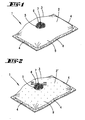
- FIG. 1 describes a latent heat storage body according to the invention 1, which is designed as a heat pad is. It has a vapor diffusion impermeable Envelope 2 on in the embodiment shown is formed from a film along an envelope edge 3 is folded into a double layer, the Side edges 4 impermeable to vapor diffusion by welding are closed. As through the partial departure is recognizable in the envelope, contains the Latent heat storage body 1 in its interior Number of individual carrier material bodies 5 with capillaries Recording rooms recorded latent heat storage material 6 paraffin-based. In addition, the Surfaces of individual carrier material a grain-like hygroscopic material 7 evenly distributed arranged inside as a microwave active Material water 8 is stored. To a more detailed one Representation as well as a functional description is at this point on Figures 3a, 3b, 3c and the associated description referenced.
- FIG. 2 describes a latent heat storage body 1, that differs from that shown in Figure 1 by a vapor diffusion Wrapping 2 'differs.
- she has a micro perforation with vapor diffusion permeable Openings 9 on the entire surface are distributed.
- one size is the Openings 9 selected, in which the openings only steam let through.
- the bag is still there fully operational if larger openings, e.g. in the Range up to approx. 0.2 - 0.3 mm are available.
- “open system” allow the Openings 9 when heating a steam outlet in the Environment and when cooling a need-based regeneration of the latent heat storage body with moisture from the area.
- the "closed system” is thus the “open system” System "even small leaks, like this one Welding can occur, negligible. from that this results in a significant reduction in the reject rate in production, which is also a cost reduction means in the quality inspection.
- a sticking of Diffusion openings due to excess Paraffin can, for example, by targeted coordination of the Ratio of opening diameter to surface tension of latent heat storage material based on paraffin be dealt with effectively, so that always enough Diffusion openings are kept clear.
- the wrapper is a Plastic film, but it can also be films from others Appropriate materials are used.
- the latent heat storage body shown in Figures 1 and 2 can be put in a microwave which is then put into operation. power stage and exposure time of the microwaves to the product depend on the size or thickness of the desired Temperature and the intended heating time of the product. Depending on the parameter selection, the latent heat storage body is after a few minutes so far evenly heated that all the paraffin contained therein has melted.
- Figure 3a shows an enlarged view of a part the in the latent heat storage body according to Figures 1 and 2 contained carrier material individual body 5 with therein in capillary recording rooms of stored latent heat storage material 6 based on paraffin, the Surfaces of the individual carrier material 5 evenly distributed grains of hygroscopic material 7 are clearly recognizable.
- the microwave active Water 8 in a regenerated state of the latent heat storage body 1 within the grains is stored from hygroscopic material 7.
- FIG. 3b describes that shortly after turning on the microwave 10 through the penetrating into the latent heat storage body 1 Microwave radiation 11 to a heating-related Evaporation and thus to the first proportion Exit of the water 8 from the hygroscopic material 7 is coming.
- the steam escapes from the hygroscopic Material is through the dotted exit lines represented symbolically.
- 3b clearly shows that the heated vaporous water 8 in Cavities 12 between the individual carrier material and the hygroscopic material 7 distributed. It sweeps over the surfaces of the individual carrier material 5 or the latent heat storage material 6, the a low temperature due to the microwave passivity having.
- Cooling loads the hygroscopic material 7 again with water 8 from the air humidity, and after some Time (depending on the humidity and the Temperature) is the concentration deficit that occurs during heating at water 8, the Latent heat storage body has self again regenerated.
- Figures 3a, 3b and 3c can also be used on plates, pastes, Expand molded parts and shapes of any kind. So can e.g. also warming elements, for example in the food sector, manufacture that is not lengthy be heated in electric or steam ovens need, but very quickly in a microwave oven can be prepared for your use. From this there is a lower energy expenditure and continues lower required retention capacities.
- Figure 4 shows a sectional view of an inventive Latent heat storage body 13, which is a carrier material body 14 with it in capillary recording rooms recorded latent heat storage material 6 based on paraffin contains.
- the carrier material body 14 is a fiberboard made of PAP material, with regard to other suitable carrier materials also on the content of the PCT / EP98 / 01956.
- the surface of the substrate body 14 is covered by a film 15, which contains hygroscopic material 7.
- the slide 15 can, for example, even from a hygroscopic Material 7 may be formed, but it can alternatively or in combination with a hygroscopic Material 7 occupied or coated.
- film 15 can on the entire surface of the soaked carrier material body 14 may be provided, but it can alternatively also arranged only in certain areas and / or openings permeable to vapor diffusion exhibit.
- the latent heat storage body 1 shown also has a vapor diffusion-impermeable in the concrete example Wrapping 2 on which under training of a gas-filled space using drawings spacers not shown from the Carrier material body with the film 15 spaced apart is.
- the high-energy Steam can cause the film 15 to heat up, which in turn transfers the heat to that in the carrier material body 14 stored latent heat storage material 6 passes.
- the high-energy Steam through openings permeable to vapor diffusion in the film 15 or not from the film 15 covered surface areas of the carrier material body in direct contact with the latent heat storage material 6 occur, which results in a particularly rapid heat transfer is made possible.
- hygroscopic Material 7 also fabrics, knitted fabrics, wickerwork, Fibers and papers from microwave active, preferably good moisture-conducting and possibly capillary materials (e.g. blotting paper).
- Layer shown hygroscopic material 7 can it is, for example, a layer of hygroscopic Trade powder or granules or fine grains.
- FIG. 5 shows a latent heat storage body 17, of the latent heat storage body shown in Figure 4 13 through a closable opening 18 differs.
- the latter is concrete as one Embodiment formed from sheet material Tab 19 executed around a bending edge 20 of the vapor diffusion-impermeable casing 2 pivoted can be.
- closed state of the opening 18 in the example shown an angled one Tab portion 21 on the outside of the envelope 2 the top of the latent heat storage body adjacent to the opening 18 17. It is through a heavy duty Panel closure, for example by a Velcro connection, one of the vapor pressures permitted during operation permanent connection between the flap end and the outer envelope 2 created.
- the Tab portion 21 integrated seal 23 is in the Interact with the top outer surface of the Envelope 2 is at the same time impermeable to vapor diffusion Connection reached.
- the latent heat storage body shown in Figure 5 17 can with the opening 18 closed like that in FIG. 4 shown latent heat storage body 13 as a "closed System "can be used.
- the opening 18 opens automatically, can this after using the latent heat storage body manually opened to make a change in particular an enlargement of the contained therein Amount of microwave active moisture.
- the Latent heat storage body 17 with opening 18 together with, for example, a bowl Amount of water 8 is entered into a microwave and this is put into operation. That from the shell evaporating water 8 is initially distributed in the Environment of the latent heat storage body 17 and arrives through its opening 18 into the gas-filled space 16, from which it is from the hygroscopic material 7 in a desired amount.
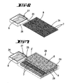
- FIG 6 is an arrangement of a distribution body 24 and one connected to it by means of a line 25 Container 26 containing water 8 is shown.
- the Line 25 can by means of a fitting 27 for one Water flow can be blocked or released. How is shown, are on the distribution body 24th distributed grains of hygroscopic material 7 arranged.
- the distribution body 24 also has capillary spaces on the paths to the hygroscopic material 7 open or form. It is preferably provided that the capillary spaces are designed in such a way that they only for the microwave active water 8, not against it for the highly viscous latent heat storage material 6 are capillary.
- the distribution body 24 may be preferred be designed as a "capillary network", in which the capillary spaces are network-like.
- FIG. 7 describes a latent heat storage body 28 with built-in arrangement according to Figure 6.
- the concrete body 24 is a concrete example between two parallel plate-shaped Individual carrier material bodies 29 with therein in Capillary-like recording rooms containing latent heat storage material 6 paraffin-based.
- the latent heat storage body 28 continues to be vapor permeable Envelope 2 'surrounded by the the line 25 from the container 26 into the interior of the Latent heat storage body enters. Operational this latent heat storage body is in the distribution body and stored in the hygroscopic material 7 Water 8 evaporates at least partially and flows while giving off heat to the Latent heat storage material 6 also on the distribution body 24 facing surfaces of the plates 29 along.
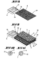
- the arrangement shown in FIG. 8 also distinguishes differs from that shown in Figure 6 by referring to the Arrangement of hygroscopic material 7 on the distribution body is waived. This can also make sense be if the distribution body is not itself out a hygroscopic material 7 is formed therefor but - as shown in Figure 9 - between the adjacent ones Carrier material individual bodies 5 with accommodated therein Latent heat storage material 6 hygroscopic material 7 is arranged distributed.
- Latent heat storage body 30 are the with Latent heat storage material 6 soaked individual carrier material 5 with the hygroscopic distributed in between Material formed into plates 29 between which the distribution body 24 is arranged.
- Hygroscopic material 7 formed bodies are there from a drawing, not shown, for latent heat storage material 6 enclosed impermeable film, where the film is a number of tiny holes, that are just barely visible macroscopically.
- the film is a number of tiny holes, that are just barely visible macroscopically.
- the hygroscopic Material 7 storable moisture, in particular Water, the film through the tiny holes passes through, so that the hygroscopic material 7 moisture can give to the environment or from the environment can record. Because of the three-dimensional shown Distribution of the hygroscopic material 7 becomes independent regeneration after heating through moisture absorption through the vapor diffusion permeable Envelope 2 'supported from the environment.
- FIG. 10 shows a latent heat storage body 31, where around a core area of microwave passive or microwave active latent heat storage material 6 a continuous layer of paraffin hygroscopic material 7 is arranged.
- a microwave activation of the latent heat storage body 31 reached.
- Figure 11 shows a latent heat storage body 32 which in Inside the latent heat storage material 6 a core area made of a hygroscopic material 7.
- the latent heat storage material in capillary receiving spaces of a carrier material body is recorded. It is also thought that a larger number of those shown in Figures 10 and 11 Latent heat storage body as a partial latent heat storage body can be used by a plurality of Together with you in a latent heat storage body larger dimensions is added.
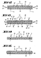
- Figure 12 shows a sectional view of a heat storage device 33, the sandwich of two itself extending plate-like perpendicular to the plane of the drawing Heat storage elements 34, 34 'made of heat storage material and one between these heat storage elements 34, 34 'arranged in the form of an intermediate layer hygroscopic Material 7 is formed.
- the cohesion of the layer composite is based on the exemplary embodiment on a horizontal, as shown Arrangement of the heat storage device and the vertical acting gravity. Cohesion can alternatively supported by fasteners or can be achieved, the selection of which in the oriented to the materials used. Unless it is the heat storage elements 34, 34 'e.g.
- Heat storage elements 34, 34 ' Wood for example made of poplar wood, and that as a hygroscopic material 7 a powder or granulate Salt is used. In this case there is the ability to keep the layers together they penetrate positive connection elements, for example, rivets.
- microwave radiation 11 indicated microwave field penetrate the microwave rays through the heat storage elements 34, 34 ' and in a smaller one corresponding to the area ratio Proportion also over the end faces in the hygroscopic Material 7 a. That in the hygroscopic material 7 stored water, not shown in the drawing is warmed by dielectric losses and gives this inherent heat to the hygroscopic material 7 as well directly and indirectly above it to the adjacent heat storage elements 34, 34 'further.
- the one shown in FIG Heat storage device has such a Arrangement of hygroscopic material to heat storage elements or heat storage material that specifically for fast and unhindered heat transfer from heated water or heated hygroscopic material 7 onto the even colder heat storage elements 34, 34 'is matched by heat conduction by a large Contact surface provided between the individual layers is.
- the heat conduction becomes to a certain extent supported by a convective heat transfer a flow of the heat generated Water vapor through the hygroscopic material to the Surfaces of the heat storage elements 34, 34 '.
- To a A certain proportion of heat is also transferred through heat radiation to the colder heat storage elements 34, 34 '.
- the microwave or heating-related Evaporation of the stored in the hygroscopic material 7 Water is increasing in volume Water connected.
- the volume increase leads to an increase in pressure of the water vapor in the cavities of the hygroscopic material 7, which is essential Drive for one to the side edges 35, 35 'of the Heat storage device directed water vapor flow supplies. Due to the pressure drop it comes to the Side edges 35, 35 'to a water vapor outlet, due to this, the hygroscopic material 7 temporarily depleted of water vapor.
- Cooling of the heat storage device 33 has that hygroscopic material 7 the ability to the environment over its free surfaces on the side edges 35, 35 'to extract humidity.
- water vapor inflow 37 becomes the water loss balanced again, starting with that water absorbed by the edges also by diffusion the inside of the formed from hygroscopic material 7 Layer.
- water vapor inflow 37 becomes the water loss balanced again, starting with that water absorbed by the edges also by diffusion the inside of the formed from hygroscopic material 7 Layer.
- FIG. 13 describes a heat storage device in a sectional view 38, which differs from that in FIG. 12 differentiates between the heat storage device 33 shown, that in the plate-like heat storage elements 34, 34 'cavities 39 are formed, which are continuously between the hygroscopic Material 7 facing inner surface 40 and that in moisture exchange with the surrounding outside area Extend 41 of the same heat storage elements.
- the representation is symbolic in this regard it can be seen that the cavities 39 flow paths for Water vapor between the hygroscopic material and form the environment.
- the water vapor outlet 36 and Steam inflow 37 are thereby increased and run along in a more even distribution the surface of the hygroscopic material 7.
- the cavities 39 can within that perpendicular to the plane of the drawing Level in regular or irregular two-dimensional Distribution should be provided.
- FIG 14 is a third in a sectional view Embodiment of a heat storage device according to the invention 42 shown, which is also a hygroscopic Material 7 in one for heat transfer suitable arrangement on the heat storage material contains.
- the heat storage device 42 only one made of heat storage material formed heat storage element 34. This is large area with a made of hygroscopic material 7 formed layer, thereby creating an unimpeded Heat transfer from that through microwave radiation 11 heated, not shown in the drawing Water or water vapor on the heat storage element 34 and from the water or water vapor via the hygroscopic Material 7 to the heat storage element 34 enable.
- FIG 15 is a fourth in a sectional view Embodiment of a heat storage device 44 with hygroscopic material 7 and a heat storage element 34, which is different from that shown in FIG Heat storage device 42 by an additional provided elastic or rigid, pressure-resistant Shell 45 differs.
- the shell 45 is impermeable to water vapor trained so that at a by microwave radiation 11 caused heating and evaporation of the drawing not shown, in hygroscopic material 7 stored water no loss of moisture Heat storage device 44 can occur.
- the at heating from the hygroscopic material 7 escaping moisture is from between the heat storage element 34 and hygroscopic material 7 with the storage space 46 enclosed in the shell 45, so that from there a quick regeneration of the hygroscopic material 7 can take place.
- the cover 45 will refer to the further description in this regard referenced in this application.
Landscapes
- Engineering & Computer Science (AREA)
- Physics & Mathematics (AREA)
- Thermal Sciences (AREA)
- Chemical & Material Sciences (AREA)
- Mechanical Engineering (AREA)
- General Engineering & Computer Science (AREA)
- Chemical Kinetics & Catalysis (AREA)
- Combustion & Propulsion (AREA)
- Materials Engineering (AREA)
- Organic Chemistry (AREA)
- Thermotherapy And Cooling Therapy Devices (AREA)
- Central Heating Systems (AREA)
- Compositions Of Macromolecular Compounds (AREA)
- Constitution Of High-Frequency Heating (AREA)
Description
Calciumsilikat ist ein Adsorbens. Dies bedeutet, dass das Latentwärmespeichermaterial sich nur äußerlich, an der Oberfläche der Calciumsilikatpartikel, anlagern kann. Diese Calciumsilikatpartikel sind zudem sehr klein. 94% der Partikel sind kleiner als 44 µm.
- Fig. 1
- einen erfindungsgemäßen Latentwärmespeicherkörper mit einer geschlossenen Umhüllung in einer perspektivischen Ansicht mit Teilaufbruch,
- Fig. 2
- einen erfindungsgemäßen Latentwärmespeicherkörper mit einer perforierten Umhüllung in einer perspektivischen Ansicht mit Teilaufbruch,
- Fig. 3a
- das Innere des Latentwärmespeicherkörpers in einem regenerierten Zustand als Ausschnittsvergrößerung zu den Fig. 1 und 2,
- Fig. 3b
- das Innere des Latentwärmespeicherkörpers nach kurzzeitiger Erwärmung durch Mikrowellen als Ausschnittsvergrößerung zu den Fig. 1 und 2,
- Fig. 3c
- das Innere des Latentwärmespeicherkörpers nach längerer Erwärmung durch Mikrowellen als Ausschnittsvergrößerung zu den Fig. 1 und 2,
- Fig. 4
- ein zweites Ausführungsbeispiel eines Latentwärmespeicherkörpers in einer Schnittansicht,
- Fig. 5
- ein drittes Ausführungsbeispiel eines Latentwärmespeicherkörpers mit einer verschließbaren Öffnung in einer Schnittansicht,
- Fig. 6
- einen mit einem Wasserbehälter verbundenen, Kapillarräume aufweisenden Verteilkörper mit angelagertem hygroskopischen Material,
- Fig. 7
- einen Latentwärmespeicherkörper mit darin eingebautem Verteilkörper nach Fig. 6 in einer Explosionsdarstellung,
- Fig. 8
- einen Verteilkörper nach Fig. 6 ohne angelagertes hygroskopisches Material,
- Fig. 9
- einen Latentwärmespeicherkörper mit darin eingebautem Verteilkörper nach Fig. 8 in einer Explosionsdarstellung,
- Fig. 10
- einen mikrowelleninaktiven Latentwärmespeicherkörper mit einer mikrowellenaktiven Hülle in einer Schnittansicht,
- Fig. 11
- einen mikrowelleninaktiven Latentwärmespeicherkörper mit einem mikrowellenaktiven Kern,
- Fig. 12
- eine Schnittansicht durch eine erste Ausführungsform einer Wärmespeichervorrichtung mit darin enthaltenem hygroskopischem Material und zwei Wärmespeicherelementen,
- Fig. 13
- eine Schnittansicht durch eine zweite Ausführungsform einer Wärmespeichervorrichtung mit hygroskopischem Material und zwei in Wärmespeicherelementen mit durch sie hindurchgehenden Hohlräumen,
- Fig. 14
- eine Schnittansicht durch eine dritte Ausführungsform einer Wärmespeichervorrichtung mit hygroskopischem Material und einem Wärmespeicherelement,
- Fig. 15
- eine Schnittansicht durch eine Wärmespeichervorrichtung nach Fig. 14 mit einer zusätzlichen äußeren Umhüllung,
Claims (33)
- Latentwärmespeicherkörper (1, 17, 28, 30, 31, 32) mit einem Latentwärmespeichermaterial (6) auf Paraffinbasis, wobei der Latentwärmespeicherkörper ein hygroskopisches Material enthält und ein Trägermaterial, in welchem das Latentwärmespeichermaterial aufgenommen ist, dadurch gekennzeichnet, dass das Trägermaterial kapillarartige Aufnahmeräume aufweist, die eine selbstansaugende Wirkung hinsichtlich des Latentwärmespeichermaterials ausüben.
- Latentwärmespeicherkörper (1,17,28,30,31,32) nach Anspruch 1, dadurch gekennzeichnet, dass der Latentwärmespeicherkörper (1,17,28,30,31,32) in einer dampfdiffusionsdurchlässigen Umhüllung (2') aufgenommen ist.
- Latentwärmespeicherkörper (1,17,28,30,31,32) nach Anspruch 1, dadurch gekennzeichnet, dass der Latentwärmespeicherkörper (1,17,28,30,31,32) in einer dampfdiffusionsundurchlässigen Umhüllung (2) aufgenommen ist.
- Latentwärmespeicherkörper (1,17,28,30,31,32) nach einem der vorhergehenden Ansprüche , dadurch gekennzeichnet, dass das hygroskopische Material (7) in einer dampfdiffusionsdurchlässigen Umhüllung aufgenommen ist.
- Latentwärmespeicherkörper (1,17,28,30,31,32) nach einem der vorhergehenden Ansprüche, dadurch gekennzeichnet, dass das Latentwärmespeichermaterial (6) Kapillarräume aufweist, die Wege zu dem hygroskopischen Material (7) öffnen.
- Latentwärmespeicherkörper (1,17,28,30,31,32) nach einem der vorhergehenden Ansprüche, dadurch gekennzeichnet, dass das hygroskopische Material (7) im Latentwärmespeicherkörper (1,17,28,30,31,32) verteilt angeordnet ist.
- Latentwärmespeicherkörper (1,17,28,30,31,32) nach einem der vorhergehenden Ansprüche, dadurch gekennzeichnet, dass der Massenanteil des hygroskopischen Materials (7) im Latentwärmespeicherkörper (1,17,28,30,31,32) 5 % oder weniger beträgt.
- Latentwärmespeicherkörper (1,17,28,30,31,32) nach einem der vorhergehenden Ansprüche, dadurch gekennzeichnet, dass in dem Latentwärmespeicherkörper (1,17,28,30,31,32) hygroskopisches Material (7) unterschiedlicher Wirksamkeit enthalten ist.
- Latentwärmespeicherkörper (1,17,28,30,31,32) nach einem der vorhergehenden Ansprüche, dadurch gekennzeichnet, dass der Latentwärmespeicherkörper eine Anzahl von Trägermaterialeinzelkörpern (5) enthält.
- Latentwärmespeicherkörper (1,17,28,30,31,32) nach Anspruch 9, dadurch gekennzeichnet, dass der Trägermaterialeinzelkörper (5) eine plattenartige oder kornartige Gestalt aufweist.
- Latentwärmespeicherkörper (1,17,28,30,31,32) nach einem der vorhergehenden Ansprüche, dadurch gekennzeichnet, dass das hygroskopische Material (7) körnerartig oder granulatartig ausgebildet ist.
- Latentwärmespeicherkörper (1,17,28,30,31,32) nach einem der Ansprüche 1 bis 11, dadurch gekennzeichnet, dass das hygroskopische Material (7) als Pulver ausgebildet ist.
- Latentwärmespeicherkörper (1,17,28,30,31,32) nach einem der vorhergehenden Ansprüche, dadurch gekennzeichnet, dass das hygroskopische Material (7) auf einem Trägermaterialeinzelkörper (5) angeordnet ist.
- Latentwärmespeicherkörper (1,17,28,30,31,32) nach einem der Ansprüche 9 bis 13, dadurch gekennzeichnet, dass der Trägermaterialeinzelkörper (5) und die Umhüllung (2,2') von einem Gas enthaltenden Raum beabstandet angeordnet sind.
- Latentwärmespeicherkörper (1,17,28,30,31,32) nach einem der vorhergehenden Ansprüche, dadurch gekennzeichnet, dass sich in dem Latentwärmespeicherkörper (1,17,28,30,31,32) ein Verteilkörper (24) flächig und/oder räumlich erstreckt, wobei der Verteilkörper Kapillarräume aufweist, die Wege zu dem hygroskopischen Material (7) öffnen.
- Latentwärmespeicherkörper (1,17,28,30,31,32) nach einem der Ansprüche 1 bis 15, dadurch gekennzeichnet, dass auf dem Verteilkörper (24) hygroskopisches Material (7) angeordnet ist.
- Latentwärmespeicherkörper (1,17,28,30,31,32) nach Anspruch 16, dadurch gekennzeichnet, dass der Verteilkörper 24 aus einem hygroskopischen Material (7) ausgebildet ist.
- Latentwärmespeicherkörper (1,17,28,30,31,32) nach einem der vorhergehenden Ansprüche 2 bis 17, dadurch gekennzeichnet, dass die Umhüllung (2,2') des Latentwärmespeicherkörpers (1,17,28,30,31,32) eine verschließbare Öffnung (18) aufweist.
- Latentwärmespeicherkörper (1,17,28,30,31,32) nach Anspruch 18, dadurch gekennzeichnet, dass sich der Verteilkörper (24) von der verschließbaren Öffnung (18) der Umhüllung (2,2') ausgehend in den Latentwärmespeicherkörper (1,17,28,30,31,32) erstreckt.
- Latentwärmespeicherkörper (1,17,28,30,31,32) nach einem der vorhergehenden Ansprüche, dadurch gekennzeichnet, dass das Latentwärmespeichermaterial (6) ein viskositätssteigerndes Additiv enthält.
- Verfahren zur Herstellung eines hygroskopisches Material enthaltenden Latentwärmespeicherkorpers (1,17,28,30,31,32) mit in einem Aufnahmeräume aufweisenden Trägermaterial aufgenommenen Latentwärmespeichermaterial (6) auf Paraffinbasis, bei dem das Latentwärmespeichermaterial (6) verflüssigt wird und in verflüssigter Form an selbstansaugende kapillarartige Aufnahmeräume des Trägermaterials herangeführt wird, dadurch gekennzeichnet, dass das verflüssigte Latentwärmespeichermaterial (6) an eine Mehrzahl von Trägermaterialeinzelkörpern (5) eines Latentwärmespeicherkörpers (1,17,28,30,31,32) herangeführt wird.
- Verfahren nach Anspruch 21, dadurch gekennzeichnet, dass das hygroskopisches Material (7) an eine Oberfläche des Trägermaterials angelagert wird.
- Verfahren nach Anspruch 22, dadurch gekennzeichnet, dass das hygroskopische Material (7) an die Oberfläche des Trägermaterials angelagert wird, nachdem das verflüssigte Latentwärmespeichermaterial (6) an die selbstansaugenden kapillarartigen Aufnahmeräume des Trägermaterials herangeführt worden ist.
- Verfahren nach Anspruch 21, dadurch gekennzeichnet, dass ein körner- und/oder granulat- und/oder pulver- und/oder flockenartiges hygroskopisches Material (7) verwendet wird.
- Verfahren nach einem der Ansprüche 21 bis 24, dadurch gekennzeichnet, dass als Trägermaterial körner- und/oder granulat- und/oder flockenartiges Material verwendet wird.
- Verfahren nach einem der Ansprüche 21 bis 25, dadurch gekennzeichnet, dass als Trägermaterial ein Vlies verwendet wird.
- Verfahren nach einem oder mehreren der Ansprüche 21 bis 26, dadurch gekennzeichnet, dass das Trägermaterial in einer plattenartigen Ausgestaltung verwendet wird.
- Verfahren nach dem Oberbegriff von Anspruch 21, dadurch gekennzeichnet, dass ein hygroskopisches Material (7) an eine Oberfläche des Trägermaterials angelagert wird.
- Verfahren nach Anspruch 28, dadurch gekennzeichnet, dass die Anlagerung an die Oberfläche des Trägermaterials erfolgt, nachdem das verflüssigte Latentwärmespeichermaterial (6) an die selbstansaugenden kapillarartigen Aufnahmeräume des Trägermaterials herangeführt worden ist.
- Verfahren nach einem der Ansprüche 28 oder 29, dadurch gekennzeichnet, dass ein körner- und/oder granulat- und/oder pulver- und/oder flockenartiges hydroskopisches Material (7) verwendet wird.
- Verfahren nach einem der Ansprüche 28 bis 30, dadurch gekennzeichnet, dass als Trägermaterial körner- und/oder granulat- und/oder flockenartiges Material verwendet wird.
- Verfahren nach einem der Ansprüche 28 bis 31, dadurch gekennzeichnet, dass als Trägermaterial ein Vlies verwendet wird.
- Verfahren nach einem der Ansprüche 28 bis 32, dadurch gekennzeichnet, dass das Trägermaterial in einer plattenartigen Ausgestaltung verwendet wird.
Applications Claiming Priority (7)
| Application Number | Priority Date | Filing Date | Title |
|---|---|---|---|
| DE19819171 | 1998-04-29 | ||
| DE19819171 | 1998-04-29 | ||
| DE19822541 | 1998-05-19 | ||
| DE19822541 | 1998-05-19 | ||
| DE19836048A DE19836048A1 (de) | 1998-04-29 | 1998-08-10 | Mikrowellenaktivierbare Lastenwärmespeicherkörper |
| DE19836048 | 1998-08-10 | ||
| PCT/EP1999/001809 WO1999055795A1 (de) | 1998-04-29 | 1999-03-18 | Mikrowellenaktivierbare latentwärmespeicherkörper |
Publications (2)
| Publication Number | Publication Date |
|---|---|
| EP1080161A1 EP1080161A1 (de) | 2001-03-07 |
| EP1080161B1 true EP1080161B1 (de) | 2002-11-13 |
Family
ID=27218324
Family Applications (1)
| Application Number | Title | Priority Date | Filing Date |
|---|---|---|---|
| EP99910363A Expired - Lifetime EP1080161B1 (de) | 1998-04-29 | 1999-03-18 | Mikrowellenaktivierbare latentwärmespeicherkörper |
Country Status (9)
| Country | Link |
|---|---|
| EP (1) | EP1080161B1 (de) |
| AT (1) | ATE227763T1 (de) |
| AU (1) | AU752252B2 (de) |
| CA (1) | CA2330630A1 (de) |
| DK (1) | DK1080161T3 (de) |
| ES (1) | ES2186338T3 (de) |
| NO (1) | NO20005423L (de) |
| NZ (1) | NZ507814A (de) |
| WO (1) | WO1999055795A1 (de) |
Cited By (1)
| Publication number | Priority date | Publication date | Assignee | Title |
|---|---|---|---|---|
| DE102011054921A1 (de) * | 2011-10-28 | 2013-05-02 | Deutsches Zentrum für Luft- und Raumfahrt e.V. | Verfahren zur Herstellung eines Wärmespeicherelements, Wärmespeicherelement und Wärmespeichervorrichtung |
Families Citing this family (3)
| Publication number | Priority date | Publication date | Assignee | Title |
|---|---|---|---|---|
| US20050242090A1 (en) * | 2004-04-30 | 2005-11-03 | Cantu Homaro R | Cooking and serving system and methods |
| WO2012032083A1 (en) * | 2010-09-08 | 2012-03-15 | Arcelik Anonim Sirketi | An oven comprising a warmer compartment |
| IT201600127185A1 (it) * | 2016-12-15 | 2018-06-15 | Rtp S R L S | Sistema di accumulo termico e climatizzazione di un ambiente |
Family Cites Families (5)
| Publication number | Priority date | Publication date | Assignee | Title |
|---|---|---|---|---|
| US5424519A (en) * | 1993-09-21 | 1995-06-13 | Battelle Memorial Institute | Microwaved-activated thermal storage material; and method |
| US5630961A (en) * | 1993-09-21 | 1997-05-20 | Thermastor Technologies, Ltd. | Microwave-activated mixed-powder thermal storage material; and method |
| AU5919896A (en) * | 1995-05-10 | 1996-11-29 | Battelle Memorial Institute | Microwave-activated powder thermal storage composition; and method |
| US5804266A (en) * | 1996-03-28 | 1998-09-08 | The University Of Dayton | Microwavable thermal energy storage material |
| JP2001527635A (ja) * | 1997-05-21 | 2001-12-25 | シューマン・サソル・ゲーエムベーハー・ウント・ツェーオー・カーゲー | 潜熱体 |
-
1999
- 1999-03-18 AT AT99910363T patent/ATE227763T1/de not_active IP Right Cessation
- 1999-03-18 EP EP99910363A patent/EP1080161B1/de not_active Expired - Lifetime
- 1999-03-18 AU AU29344/99A patent/AU752252B2/en not_active Ceased
- 1999-03-18 CA CA002330630A patent/CA2330630A1/en not_active Abandoned
- 1999-03-18 WO PCT/EP1999/001809 patent/WO1999055795A1/de not_active Ceased
- 1999-03-18 ES ES99910363T patent/ES2186338T3/es not_active Expired - Lifetime
- 1999-03-18 NZ NZ507814A patent/NZ507814A/xx unknown
- 1999-03-18 DK DK99910363T patent/DK1080161T3/da active
-
2000
- 2000-10-27 NO NO20005423A patent/NO20005423L/no not_active Application Discontinuation
Cited By (2)
| Publication number | Priority date | Publication date | Assignee | Title |
|---|---|---|---|---|
| DE102011054921A1 (de) * | 2011-10-28 | 2013-05-02 | Deutsches Zentrum für Luft- und Raumfahrt e.V. | Verfahren zur Herstellung eines Wärmespeicherelements, Wärmespeicherelement und Wärmespeichervorrichtung |
| DE102011054921B4 (de) * | 2011-10-28 | 2020-02-27 | Deutsches Zentrum für Luft- und Raumfahrt e.V. | Verfahren zur Herstellung eines Wärmespeicherelements, Wärmespeicherelement und Wärmespeichervorrichtung |
Also Published As
| Publication number | Publication date |
|---|---|
| NZ507814A (en) | 2002-11-26 |
| ATE227763T1 (de) | 2002-11-15 |
| NO20005423L (no) | 2000-12-29 |
| NO20005423D0 (no) | 2000-10-27 |
| DK1080161T3 (da) | 2003-03-10 |
| WO1999055795A1 (de) | 1999-11-04 |
| AU2934499A (en) | 1999-11-16 |
| ES2186338T3 (es) | 2003-05-01 |
| AU752252B2 (en) | 2002-09-12 |
| CA2330630A1 (en) | 1999-11-04 |
| EP1080161A1 (de) | 2001-03-07 |
Similar Documents
| Publication | Publication Date | Title |
|---|---|---|
| EP0983474B1 (de) | Latentwärmekörper | |
| DE19813562A1 (de) | Latentwärmekörper | |
| EP2671038B1 (de) | Latentwärmespeicher | |
| EP1764136B1 (de) | Mit wirkstoffhaltigen Mikrokapseln beaufschlagtes funktionelles Textilmaterial und seine Verwendung | |
| WO2015177168A1 (de) | Flexible pcm-flächengebilde | |
| US11643584B2 (en) | Incorporation of microencapsulated phase change materials into wet-spin dry jet polymeric fibers | |
| DE102016013415A1 (de) | Verfahren zur Herstellung eines formstabilen, auslaufsicheren Phase Change Material System (PCM - S) | |
| EP1108193B1 (de) | Latentwärmekörper mit porenstruktur und verfahren zu dessen herstellung | |
| DE19836048A1 (de) | Mikrowellenaktivierbare Lastenwärmespeicherkörper | |
| DE2227533C3 (de) | Verfahren zur Herstellung von Filterkörpern aus Aktivkohlekörnern und einem feinverteilten thermoplastischen Bindemittel | |
| DE10200316A1 (de) | Kunststoffteil und Verfahren zur Herstellung eines Kunststoffteiles | |
| EP1080161A1 (de) | Mikrowellenaktivierbare latentwärmespeicherkörper | |
| DE102005000022A1 (de) | Sorbierender Formkörper, Verfahren zur Herstellung und Verwendung | |
| DE102020002843A1 (de) | Verfahren zur Herstellung eines formstabilen und auslaufsicheren Energiespeichermedium | |
| DE10338327B3 (de) | Holzwolle- Bauprodukt oder substantieller Bestandteil eines Holzwolle-Bauproduktes | |
| AT509335B1 (de) | Latentwärmespeicher mit klimatisierungskörpern | |
| EP3377833B1 (de) | Vorrichtung zum kühlen einer flüssigkeit sowie verwendung der vorrichtung als bauteil für eine vorratsanordnung | |
| EP4185640B1 (de) | Rieselfähiges gemisch, dessen verwendung und verfahren zu dessen herstellung | |
| DE102011053308A1 (de) | Phasenwechselmaterial-Zusammensetzung und daraus hergestelltes Latentwärmespeicherelement; Verfahren zur Herstellung eines Latentwärmespeicherelements und Verfahren zur Konditionierung eines Mediums mittels des Latentwärmespeicherelements | |
| EP2874581B1 (de) | Heizpackung, insbesondere zur wärmung von körperteilen | |
| DE102019007479A1 (de) | Verfahren zur Herstellung eines formstabilen und auslaufsicheren Energiespeichermedium geeignet für den Einsatz in Latentwärmespeicherdecken | |
| DE202010015290U1 (de) | Latentwärmespeicher mit einem Phasenwechselmaterial mit einem Viskositätseinsteller | |
| DE10021261A1 (de) | Metallhaltiger und mineralische Granalien, insbesondere zeolithische Granalien enthaltenden Schichtkörper und Verfahren zu dessen Herstellung | |
| DE10333668A1 (de) | Verfahren zur Herstellung von gebundenen Latentwärmespeichern | |
| AT4174U1 (de) | Wärmedämmendes, flexibles flächengebilde |
Legal Events
| Date | Code | Title | Description |
|---|---|---|---|
| PUAI | Public reference made under article 153(3) epc to a published international application that has entered the european phase |
Free format text: ORIGINAL CODE: 0009012 |
|
| 17P | Request for examination filed |
Effective date: 20001026 |
|
| AK | Designated contracting states |
Kind code of ref document: A1 Designated state(s): AT BE CH DE DK ES FI FR GB IT LI NL SE |
|
| 17Q | First examination report despatched |
Effective date: 20010228 |
|
| GRAG | Despatch of communication of intention to grant |
Free format text: ORIGINAL CODE: EPIDOS AGRA |
|
| GRAG | Despatch of communication of intention to grant |
Free format text: ORIGINAL CODE: EPIDOS AGRA |
|
| GRAH | Despatch of communication of intention to grant a patent |
Free format text: ORIGINAL CODE: EPIDOS IGRA |
|
| GRAH | Despatch of communication of intention to grant a patent |
Free format text: ORIGINAL CODE: EPIDOS IGRA |
|
| GRAA | (expected) grant |
Free format text: ORIGINAL CODE: 0009210 |
|
| AK | Designated contracting states |
Kind code of ref document: B1 Designated state(s): AT BE CH DE DK ES FI FR GB IT LI NL SE |
|
| REF | Corresponds to: |
Ref document number: 227763 Country of ref document: AT Date of ref document: 20021115 Kind code of ref document: T |
|
| REG | Reference to a national code |
Ref country code: GB Ref legal event code: FG4D Free format text: NOT ENGLISH |
|
| REG | Reference to a national code |
Ref country code: CH Ref legal event code: EP |
|
| REG | Reference to a national code |
Ref country code: CH Ref legal event code: NV Representative=s name: R. A. EGLI & CO. PATENTANWAELTE |
|
| REF | Corresponds to: |
Ref document number: 59903406 Country of ref document: DE Date of ref document: 20021219 |
|
| REG | Reference to a national code |
Ref country code: DK Ref legal event code: T3 |
|
| PGFP | Annual fee paid to national office [announced via postgrant information from national office to epo] |
Ref country code: FI Payment date: 20030311 Year of fee payment: 5 |
|
| ET | Fr: translation filed | ||
| PG25 | Lapsed in a contracting state [announced via postgrant information from national office to epo] |
Ref country code: GB Free format text: LAPSE BECAUSE OF NON-PAYMENT OF DUE FEES Effective date: 20030318 |
|
| PG25 | Lapsed in a contracting state [announced via postgrant information from national office to epo] |
Ref country code: ES Free format text: LAPSE BECAUSE OF NON-PAYMENT OF DUE FEES Effective date: 20030320 |
|
| PG25 | Lapsed in a contracting state [announced via postgrant information from national office to epo] |
Ref country code: DK Free format text: LAPSE BECAUSE OF NON-PAYMENT OF DUE FEES Effective date: 20030331 Ref country code: BE Free format text: LAPSE BECAUSE OF NON-PAYMENT OF DUE FEES Effective date: 20030331 |
|
| GBT | Gb: translation of ep patent filed (gb section 77(6)(a)/1977) |
Effective date: 20030319 |
|
| REG | Reference to a national code |
Ref country code: ES Ref legal event code: FG2A Ref document number: 2186338 Country of ref document: ES Kind code of ref document: T3 |
|
| PLBE | No opposition filed within time limit |
Free format text: ORIGINAL CODE: 0009261 |
|
| STAA | Information on the status of an ep patent application or granted ep patent |
Free format text: STATUS: NO OPPOSITION FILED WITHIN TIME LIMIT |
|
| BERE | Be: lapsed |
Owner name: *SCHUMANN SASOL G.M.B.H. Effective date: 20030331 |
|
| REG | Reference to a national code |
Ref country code: DK Ref legal event code: EBP |
|
| 26N | No opposition filed |
Effective date: 20030814 |
|
| GBPC | Gb: european patent ceased through non-payment of renewal fee |
Effective date: 20030318 |
|
| PGFP | Annual fee paid to national office [announced via postgrant information from national office to epo] |
Ref country code: FR Payment date: 20040304 Year of fee payment: 6 |
|
| PGFP | Annual fee paid to national office [announced via postgrant information from national office to epo] |
Ref country code: SE Payment date: 20040308 Year of fee payment: 6 Ref country code: AT Payment date: 20040308 Year of fee payment: 6 |
|
| PGFP | Annual fee paid to national office [announced via postgrant information from national office to epo] |
Ref country code: CH Payment date: 20040309 Year of fee payment: 6 |
|
| PG25 | Lapsed in a contracting state [announced via postgrant information from national office to epo] |
Ref country code: FI Free format text: LAPSE BECAUSE OF NON-PAYMENT OF DUE FEES Effective date: 20040318 |
|
| REG | Reference to a national code |
Ref country code: ES Ref legal event code: FD2A Effective date: 20030320 |
|
| PGFP | Annual fee paid to national office [announced via postgrant information from national office to epo] |
Ref country code: DE Payment date: 20050304 Year of fee payment: 7 |
|
| PGFP | Annual fee paid to national office [announced via postgrant information from national office to epo] |
Ref country code: NL Payment date: 20050309 Year of fee payment: 7 |
|
| PG25 | Lapsed in a contracting state [announced via postgrant information from national office to epo] |
Ref country code: IT Free format text: LAPSE BECAUSE OF NON-PAYMENT OF DUE FEES;WARNING: LAPSES OF ITALIAN PATENTS WITH EFFECTIVE DATE BEFORE 2007 MAY HAVE OCCURRED AT ANY TIME BEFORE 2007. THE CORRECT EFFECTIVE DATE MAY BE DIFFERENT FROM THE ONE RECORDED. Effective date: 20050318 Ref country code: AT Free format text: LAPSE BECAUSE OF NON-PAYMENT OF DUE FEES Effective date: 20050318 |
|
| PG25 | Lapsed in a contracting state [announced via postgrant information from national office to epo] |
Ref country code: SE Free format text: LAPSE BECAUSE OF NON-PAYMENT OF DUE FEES Effective date: 20050319 |
|
| PG25 | Lapsed in a contracting state [announced via postgrant information from national office to epo] |
Ref country code: LI Free format text: LAPSE BECAUSE OF NON-PAYMENT OF DUE FEES Effective date: 20050331 Ref country code: CH Free format text: LAPSE BECAUSE OF NON-PAYMENT OF DUE FEES Effective date: 20050331 |
|
| EUG | Se: european patent has lapsed | ||
| REG | Reference to a national code |
Ref country code: CH Ref legal event code: PL |
|
| PG25 | Lapsed in a contracting state [announced via postgrant information from national office to epo] |
Ref country code: FR Free format text: LAPSE BECAUSE OF NON-PAYMENT OF DUE FEES Effective date: 20051130 |
|
| REG | Reference to a national code |
Ref country code: FR Ref legal event code: ST Effective date: 20051130 |
|
| PG25 | Lapsed in a contracting state [announced via postgrant information from national office to epo] |
Ref country code: NL Free format text: LAPSE BECAUSE OF NON-PAYMENT OF DUE FEES Effective date: 20061001 |
|
| PG25 | Lapsed in a contracting state [announced via postgrant information from national office to epo] |
Ref country code: DE Free format text: LAPSE BECAUSE OF NON-PAYMENT OF DUE FEES Effective date: 20061003 |
|
| NLV4 | Nl: lapsed or anulled due to non-payment of the annual fee |
Effective date: 20061001 |