EP1081005B1 - Dispositif de freinage pour véhicule et procédé de freinage pour véhicule - Google Patents
Dispositif de freinage pour véhicule et procédé de freinage pour véhicule Download PDFInfo
- Publication number
- EP1081005B1 EP1081005B1 EP00119006A EP00119006A EP1081005B1 EP 1081005 B1 EP1081005 B1 EP 1081005B1 EP 00119006 A EP00119006 A EP 00119006A EP 00119006 A EP00119006 A EP 00119006A EP 1081005 B1 EP1081005 B1 EP 1081005B1
- Authority
- EP
- European Patent Office
- Prior art keywords
- braking force
- braking
- hydraulic
- force
- pressure
- Prior art date
- Legal status (The legal status is an assumption and is not a legal conclusion. Google has not performed a legal analysis and makes no representation as to the accuracy of the status listed.)
- Expired - Lifetime
Links
- 238000000034 method Methods 0.000 title claims description 17
- 230000001172 regenerating effect Effects 0.000 claims description 191
- 239000012530 fluid Substances 0.000 claims description 40
- 230000001105 regulatory effect Effects 0.000 claims description 36
- 230000007246 mechanism Effects 0.000 claims description 20
- 230000001276 controlling effect Effects 0.000 claims description 14
- 239000013589 supplement Substances 0.000 claims description 10
- 238000011144 upstream manufacturing Methods 0.000 claims description 9
- 230000008929 regeneration Effects 0.000 description 34
- 238000011069 regeneration method Methods 0.000 description 34
- 238000012545 processing Methods 0.000 description 20
- 230000004044 response Effects 0.000 description 19
- ZZUFCTLCJUWOSV-UHFFFAOYSA-N furosemide Chemical compound C1=C(Cl)C(S(=O)(=O)N)=CC(C(O)=O)=C1NCC1=CC=CO1 ZZUFCTLCJUWOSV-UHFFFAOYSA-N 0.000 description 18
- 238000010586 diagram Methods 0.000 description 17
- 230000000994 depressogenic effect Effects 0.000 description 15
- 230000007423 decrease Effects 0.000 description 9
- 230000000694 effects Effects 0.000 description 9
- 101000633445 Homo sapiens Structural maintenance of chromosomes protein 2 Proteins 0.000 description 8
- 102100029538 Structural maintenance of chromosomes protein 1A Human genes 0.000 description 8
- 102100029540 Structural maintenance of chromosomes protein 2 Human genes 0.000 description 8
- 108010004731 structural maintenance of chromosome protein 1 Proteins 0.000 description 8
- 238000005299 abrasion Methods 0.000 description 6
- 230000033228 biological regulation Effects 0.000 description 6
- 238000007599 discharging Methods 0.000 description 5
- 230000008859 change Effects 0.000 description 3
- 230000001419 dependent effect Effects 0.000 description 3
- 230000006870 function Effects 0.000 description 3
- 230000009191 jumping Effects 0.000 description 3
- 238000012544 monitoring process Methods 0.000 description 3
- XEEYBQQBJWHFJM-UHFFFAOYSA-N Iron Chemical group [Fe] XEEYBQQBJWHFJM-UHFFFAOYSA-N 0.000 description 2
- 230000003213 activating effect Effects 0.000 description 2
- 238000005192 partition Methods 0.000 description 2
- 238000004891 communication Methods 0.000 description 1
- 230000000881 depressing effect Effects 0.000 description 1
- 238000009434 installation Methods 0.000 description 1
- 238000012827 research and development Methods 0.000 description 1
Images













Classifications
-
- B—PERFORMING OPERATIONS; TRANSPORTING
- B60—VEHICLES IN GENERAL
- B60T—VEHICLE BRAKE CONTROL SYSTEMS OR PARTS THEREOF; BRAKE CONTROL SYSTEMS OR PARTS THEREOF, IN GENERAL; ARRANGEMENT OF BRAKING ELEMENTS ON VEHICLES IN GENERAL; PORTABLE DEVICES FOR PREVENTING UNWANTED MOVEMENT OF VEHICLES; VEHICLE MODIFICATIONS TO FACILITATE COOLING OF BRAKES
- B60T15/00—Construction arrangement, or operation of valves incorporated in power brake systems and not covered by groups B60T11/00 or B60T13/00
- B60T15/02—Application and release valves
- B60T15/025—Electrically controlled valves
- B60T15/028—Electrically controlled valves in hydraulic systems
-
- B—PERFORMING OPERATIONS; TRANSPORTING
- B60—VEHICLES IN GENERAL
- B60L—PROPULSION OF ELECTRICALLY-PROPELLED VEHICLES; SUPPLYING ELECTRIC POWER FOR AUXILIARY EQUIPMENT OF ELECTRICALLY-PROPELLED VEHICLES; ELECTRODYNAMIC BRAKE SYSTEMS FOR VEHICLES IN GENERAL; MAGNETIC SUSPENSION OR LEVITATION FOR VEHICLES; MONITORING OPERATING VARIABLES OF ELECTRICALLY-PROPELLED VEHICLES; ELECTRIC SAFETY DEVICES FOR ELECTRICALLY-PROPELLED VEHICLES
- B60L7/00—Electrodynamic brake systems for vehicles in general
- B60L7/003—Dynamic electric braking by short circuiting the motor
-
- B—PERFORMING OPERATIONS; TRANSPORTING
- B60—VEHICLES IN GENERAL
- B60L—PROPULSION OF ELECTRICALLY-PROPELLED VEHICLES; SUPPLYING ELECTRIC POWER FOR AUXILIARY EQUIPMENT OF ELECTRICALLY-PROPELLED VEHICLES; ELECTRODYNAMIC BRAKE SYSTEMS FOR VEHICLES IN GENERAL; MAGNETIC SUSPENSION OR LEVITATION FOR VEHICLES; MONITORING OPERATING VARIABLES OF ELECTRICALLY-PROPELLED VEHICLES; ELECTRIC SAFETY DEVICES FOR ELECTRICALLY-PROPELLED VEHICLES
- B60L7/00—Electrodynamic brake systems for vehicles in general
- B60L7/24—Electrodynamic brake systems for vehicles in general with additional mechanical or electromagnetic braking
- B60L7/26—Controlling the braking effect
-
- B—PERFORMING OPERATIONS; TRANSPORTING
- B60—VEHICLES IN GENERAL
- B60T—VEHICLE BRAKE CONTROL SYSTEMS OR PARTS THEREOF; BRAKE CONTROL SYSTEMS OR PARTS THEREOF, IN GENERAL; ARRANGEMENT OF BRAKING ELEMENTS ON VEHICLES IN GENERAL; PORTABLE DEVICES FOR PREVENTING UNWANTED MOVEMENT OF VEHICLES; VEHICLE MODIFICATIONS TO FACILITATE COOLING OF BRAKES
- B60T1/00—Arrangements of braking elements, i.e. of those parts where braking effect occurs specially for vehicles
- B60T1/02—Arrangements of braking elements, i.e. of those parts where braking effect occurs specially for vehicles acting by retarding wheels
- B60T1/10—Arrangements of braking elements, i.e. of those parts where braking effect occurs specially for vehicles acting by retarding wheels by utilising wheel movement for accumulating energy, e.g. driving air compressors
-
- B—PERFORMING OPERATIONS; TRANSPORTING
- B60—VEHICLES IN GENERAL
- B60T—VEHICLE BRAKE CONTROL SYSTEMS OR PARTS THEREOF; BRAKE CONTROL SYSTEMS OR PARTS THEREOF, IN GENERAL; ARRANGEMENT OF BRAKING ELEMENTS ON VEHICLES IN GENERAL; PORTABLE DEVICES FOR PREVENTING UNWANTED MOVEMENT OF VEHICLES; VEHICLE MODIFICATIONS TO FACILITATE COOLING OF BRAKES
- B60T13/00—Transmitting braking action from initiating means to ultimate brake actuator with power assistance or drive; Brake systems incorporating such transmitting means, e.g. air-pressure brake systems
- B60T13/10—Transmitting braking action from initiating means to ultimate brake actuator with power assistance or drive; Brake systems incorporating such transmitting means, e.g. air-pressure brake systems with fluid assistance, drive, or release
- B60T13/66—Electrical control in fluid-pressure brake systems
- B60T13/662—Electrical control in fluid-pressure brake systems characterised by specified functions of the control system components
-
- B—PERFORMING OPERATIONS; TRANSPORTING
- B60—VEHICLES IN GENERAL
- B60T—VEHICLE BRAKE CONTROL SYSTEMS OR PARTS THEREOF; BRAKE CONTROL SYSTEMS OR PARTS THEREOF, IN GENERAL; ARRANGEMENT OF BRAKING ELEMENTS ON VEHICLES IN GENERAL; PORTABLE DEVICES FOR PREVENTING UNWANTED MOVEMENT OF VEHICLES; VEHICLE MODIFICATIONS TO FACILITATE COOLING OF BRAKES
- B60T13/00—Transmitting braking action from initiating means to ultimate brake actuator with power assistance or drive; Brake systems incorporating such transmitting means, e.g. air-pressure brake systems
- B60T13/10—Transmitting braking action from initiating means to ultimate brake actuator with power assistance or drive; Brake systems incorporating such transmitting means, e.g. air-pressure brake systems with fluid assistance, drive, or release
- B60T13/66—Electrical control in fluid-pressure brake systems
- B60T13/72—Electrical control in fluid-pressure brake systems in vacuum systems or vacuum booster units
-
- B—PERFORMING OPERATIONS; TRANSPORTING
- B60—VEHICLES IN GENERAL
- B60T—VEHICLE BRAKE CONTROL SYSTEMS OR PARTS THEREOF; BRAKE CONTROL SYSTEMS OR PARTS THEREOF, IN GENERAL; ARRANGEMENT OF BRAKING ELEMENTS ON VEHICLES IN GENERAL; PORTABLE DEVICES FOR PREVENTING UNWANTED MOVEMENT OF VEHICLES; VEHICLE MODIFICATIONS TO FACILITATE COOLING OF BRAKES
- B60T13/00—Transmitting braking action from initiating means to ultimate brake actuator with power assistance or drive; Brake systems incorporating such transmitting means, e.g. air-pressure brake systems
- B60T13/74—Transmitting braking action from initiating means to ultimate brake actuator with power assistance or drive; Brake systems incorporating such transmitting means, e.g. air-pressure brake systems with electrical assistance or drive
- B60T13/748—Transmitting braking action from initiating means to ultimate brake actuator with power assistance or drive; Brake systems incorporating such transmitting means, e.g. air-pressure brake systems with electrical assistance or drive acting on electro-magnetic brakes
-
- B—PERFORMING OPERATIONS; TRANSPORTING
- B60—VEHICLES IN GENERAL
- B60T—VEHICLE BRAKE CONTROL SYSTEMS OR PARTS THEREOF; BRAKE CONTROL SYSTEMS OR PARTS THEREOF, IN GENERAL; ARRANGEMENT OF BRAKING ELEMENTS ON VEHICLES IN GENERAL; PORTABLE DEVICES FOR PREVENTING UNWANTED MOVEMENT OF VEHICLES; VEHICLE MODIFICATIONS TO FACILITATE COOLING OF BRAKES
- B60T7/00—Brake-action initiating means
- B60T7/02—Brake-action initiating means for personal initiation
- B60T7/04—Brake-action initiating means for personal initiation foot actuated
-
- B—PERFORMING OPERATIONS; TRANSPORTING
- B60—VEHICLES IN GENERAL
- B60T—VEHICLE BRAKE CONTROL SYSTEMS OR PARTS THEREOF; BRAKE CONTROL SYSTEMS OR PARTS THEREOF, IN GENERAL; ARRANGEMENT OF BRAKING ELEMENTS ON VEHICLES IN GENERAL; PORTABLE DEVICES FOR PREVENTING UNWANTED MOVEMENT OF VEHICLES; VEHICLE MODIFICATIONS TO FACILITATE COOLING OF BRAKES
- B60T8/00—Arrangements for adjusting wheel-braking force to meet varying vehicular or ground-surface conditions, e.g. limiting or varying distribution of braking force
-
- B—PERFORMING OPERATIONS; TRANSPORTING
- B60—VEHICLES IN GENERAL
- B60T—VEHICLE BRAKE CONTROL SYSTEMS OR PARTS THEREOF; BRAKE CONTROL SYSTEMS OR PARTS THEREOF, IN GENERAL; ARRANGEMENT OF BRAKING ELEMENTS ON VEHICLES IN GENERAL; PORTABLE DEVICES FOR PREVENTING UNWANTED MOVEMENT OF VEHICLES; VEHICLE MODIFICATIONS TO FACILITATE COOLING OF BRAKES
- B60T8/00—Arrangements for adjusting wheel-braking force to meet varying vehicular or ground-surface conditions, e.g. limiting or varying distribution of braking force
- B60T8/32—Arrangements for adjusting wheel-braking force to meet varying vehicular or ground-surface conditions, e.g. limiting or varying distribution of braking force responsive to a speed condition, e.g. acceleration or deceleration
- B60T8/34—Arrangements for adjusting wheel-braking force to meet varying vehicular or ground-surface conditions, e.g. limiting or varying distribution of braking force responsive to a speed condition, e.g. acceleration or deceleration having a fluid pressure regulator responsive to a speed condition
- B60T8/36—Arrangements for adjusting wheel-braking force to meet varying vehicular or ground-surface conditions, e.g. limiting or varying distribution of braking force responsive to a speed condition, e.g. acceleration or deceleration having a fluid pressure regulator responsive to a speed condition including a pilot valve responding to an electromagnetic force
- B60T8/3615—Electromagnetic valves specially adapted for anti-lock brake and traction control systems
- B60T8/3655—Continuously controlled electromagnetic valves
-
- B—PERFORMING OPERATIONS; TRANSPORTING
- B60—VEHICLES IN GENERAL
- B60T—VEHICLE BRAKE CONTROL SYSTEMS OR PARTS THEREOF; BRAKE CONTROL SYSTEMS OR PARTS THEREOF, IN GENERAL; ARRANGEMENT OF BRAKING ELEMENTS ON VEHICLES IN GENERAL; PORTABLE DEVICES FOR PREVENTING UNWANTED MOVEMENT OF VEHICLES; VEHICLE MODIFICATIONS TO FACILITATE COOLING OF BRAKES
- B60T8/00—Arrangements for adjusting wheel-braking force to meet varying vehicular or ground-surface conditions, e.g. limiting or varying distribution of braking force
- B60T8/32—Arrangements for adjusting wheel-braking force to meet varying vehicular or ground-surface conditions, e.g. limiting or varying distribution of braking force responsive to a speed condition, e.g. acceleration or deceleration
- B60T8/34—Arrangements for adjusting wheel-braking force to meet varying vehicular or ground-surface conditions, e.g. limiting or varying distribution of braking force responsive to a speed condition, e.g. acceleration or deceleration having a fluid pressure regulator responsive to a speed condition
- B60T8/36—Arrangements for adjusting wheel-braking force to meet varying vehicular or ground-surface conditions, e.g. limiting or varying distribution of braking force responsive to a speed condition, e.g. acceleration or deceleration having a fluid pressure regulator responsive to a speed condition including a pilot valve responding to an electromagnetic force
- B60T8/3615—Electromagnetic valves specially adapted for anti-lock brake and traction control systems
- B60T8/3655—Continuously controlled electromagnetic valves
- B60T8/366—Valve details
- B60T8/367—Seat valves, e.g. poppet valves
-
- B—PERFORMING OPERATIONS; TRANSPORTING
- B60—VEHICLES IN GENERAL
- B60T—VEHICLE BRAKE CONTROL SYSTEMS OR PARTS THEREOF; BRAKE CONTROL SYSTEMS OR PARTS THEREOF, IN GENERAL; ARRANGEMENT OF BRAKING ELEMENTS ON VEHICLES IN GENERAL; PORTABLE DEVICES FOR PREVENTING UNWANTED MOVEMENT OF VEHICLES; VEHICLE MODIFICATIONS TO FACILITATE COOLING OF BRAKES
- B60T8/00—Arrangements for adjusting wheel-braking force to meet varying vehicular or ground-surface conditions, e.g. limiting or varying distribution of braking force
- B60T8/32—Arrangements for adjusting wheel-braking force to meet varying vehicular or ground-surface conditions, e.g. limiting or varying distribution of braking force responsive to a speed condition, e.g. acceleration or deceleration
- B60T8/34—Arrangements for adjusting wheel-braking force to meet varying vehicular or ground-surface conditions, e.g. limiting or varying distribution of braking force responsive to a speed condition, e.g. acceleration or deceleration having a fluid pressure regulator responsive to a speed condition
- B60T8/40—Arrangements for adjusting wheel-braking force to meet varying vehicular or ground-surface conditions, e.g. limiting or varying distribution of braking force responsive to a speed condition, e.g. acceleration or deceleration having a fluid pressure regulator responsive to a speed condition comprising an additional fluid circuit including fluid pressurising means for modifying the pressure of the braking fluid, e.g. including wheel driven pumps for detecting a speed condition, or pumps which are controlled by means independent of the braking system
- B60T8/4072—Systems in which a driver input signal is used as a control signal for the additional fluid circuit which is normally used for braking
- B60T8/4081—Systems with stroke simulating devices for driver input
-
- B—PERFORMING OPERATIONS; TRANSPORTING
- B60—VEHICLES IN GENERAL
- B60T—VEHICLE BRAKE CONTROL SYSTEMS OR PARTS THEREOF; BRAKE CONTROL SYSTEMS OR PARTS THEREOF, IN GENERAL; ARRANGEMENT OF BRAKING ELEMENTS ON VEHICLES IN GENERAL; PORTABLE DEVICES FOR PREVENTING UNWANTED MOVEMENT OF VEHICLES; VEHICLE MODIFICATIONS TO FACILITATE COOLING OF BRAKES
- B60T8/00—Arrangements for adjusting wheel-braking force to meet varying vehicular or ground-surface conditions, e.g. limiting or varying distribution of braking force
- B60T8/32—Arrangements for adjusting wheel-braking force to meet varying vehicular or ground-surface conditions, e.g. limiting or varying distribution of braking force responsive to a speed condition, e.g. acceleration or deceleration
- B60T8/34—Arrangements for adjusting wheel-braking force to meet varying vehicular or ground-surface conditions, e.g. limiting or varying distribution of braking force responsive to a speed condition, e.g. acceleration or deceleration having a fluid pressure regulator responsive to a speed condition
- B60T8/44—Arrangements for adjusting wheel-braking force to meet varying vehicular or ground-surface conditions, e.g. limiting or varying distribution of braking force responsive to a speed condition, e.g. acceleration or deceleration having a fluid pressure regulator responsive to a speed condition co-operating with a power-assist booster means associated with a master cylinder for controlling the release and reapplication of brake pressure through an interaction with the power assist device, i.e. open systems
- B60T8/441—Arrangements for adjusting wheel-braking force to meet varying vehicular or ground-surface conditions, e.g. limiting or varying distribution of braking force responsive to a speed condition, e.g. acceleration or deceleration having a fluid pressure regulator responsive to a speed condition co-operating with a power-assist booster means associated with a master cylinder for controlling the release and reapplication of brake pressure through an interaction with the power assist device, i.e. open systems using hydraulic boosters
-
- B—PERFORMING OPERATIONS; TRANSPORTING
- B60—VEHICLES IN GENERAL
- B60T—VEHICLE BRAKE CONTROL SYSTEMS OR PARTS THEREOF; BRAKE CONTROL SYSTEMS OR PARTS THEREOF, IN GENERAL; ARRANGEMENT OF BRAKING ELEMENTS ON VEHICLES IN GENERAL; PORTABLE DEVICES FOR PREVENTING UNWANTED MOVEMENT OF VEHICLES; VEHICLE MODIFICATIONS TO FACILITATE COOLING OF BRAKES
- B60T8/00—Arrangements for adjusting wheel-braking force to meet varying vehicular or ground-surface conditions, e.g. limiting or varying distribution of braking force
- B60T8/32—Arrangements for adjusting wheel-braking force to meet varying vehicular or ground-surface conditions, e.g. limiting or varying distribution of braking force responsive to a speed condition, e.g. acceleration or deceleration
- B60T8/34—Arrangements for adjusting wheel-braking force to meet varying vehicular or ground-surface conditions, e.g. limiting or varying distribution of braking force responsive to a speed condition, e.g. acceleration or deceleration having a fluid pressure regulator responsive to a speed condition
- B60T8/44—Arrangements for adjusting wheel-braking force to meet varying vehicular or ground-surface conditions, e.g. limiting or varying distribution of braking force responsive to a speed condition, e.g. acceleration or deceleration having a fluid pressure regulator responsive to a speed condition co-operating with a power-assist booster means associated with a master cylinder for controlling the release and reapplication of brake pressure through an interaction with the power assist device, i.e. open systems
- B60T8/444—Arrangements for adjusting wheel-braking force to meet varying vehicular or ground-surface conditions, e.g. limiting or varying distribution of braking force responsive to a speed condition, e.g. acceleration or deceleration having a fluid pressure regulator responsive to a speed condition co-operating with a power-assist booster means associated with a master cylinder for controlling the release and reapplication of brake pressure through an interaction with the power assist device, i.e. open systems using vacuum
-
- B—PERFORMING OPERATIONS; TRANSPORTING
- B60—VEHICLES IN GENERAL
- B60W—CONJOINT CONTROL OF VEHICLE SUB-UNITS OF DIFFERENT TYPE OR DIFFERENT FUNCTION; CONTROL SYSTEMS SPECIALLY ADAPTED FOR HYBRID VEHICLES; ROAD VEHICLE DRIVE CONTROL SYSTEMS FOR PURPOSES NOT RELATED TO THE CONTROL OF A PARTICULAR SUB-UNIT
- B60W10/00—Conjoint control of vehicle sub-units of different type or different function
- B60W10/04—Conjoint control of vehicle sub-units of different type or different function including control of propulsion units
- B60W10/08—Conjoint control of vehicle sub-units of different type or different function including control of propulsion units including control of electric propulsion units, e.g. motors or generators
-
- B—PERFORMING OPERATIONS; TRANSPORTING
- B60—VEHICLES IN GENERAL
- B60W—CONJOINT CONTROL OF VEHICLE SUB-UNITS OF DIFFERENT TYPE OR DIFFERENT FUNCTION; CONTROL SYSTEMS SPECIALLY ADAPTED FOR HYBRID VEHICLES; ROAD VEHICLE DRIVE CONTROL SYSTEMS FOR PURPOSES NOT RELATED TO THE CONTROL OF A PARTICULAR SUB-UNIT
- B60W10/00—Conjoint control of vehicle sub-units of different type or different function
- B60W10/18—Conjoint control of vehicle sub-units of different type or different function including control of braking systems
- B60W10/184—Conjoint control of vehicle sub-units of different type or different function including control of braking systems with wheel brakes
-
- B—PERFORMING OPERATIONS; TRANSPORTING
- B60—VEHICLES IN GENERAL
- B60W—CONJOINT CONTROL OF VEHICLE SUB-UNITS OF DIFFERENT TYPE OR DIFFERENT FUNCTION; CONTROL SYSTEMS SPECIALLY ADAPTED FOR HYBRID VEHICLES; ROAD VEHICLE DRIVE CONTROL SYSTEMS FOR PURPOSES NOT RELATED TO THE CONTROL OF A PARTICULAR SUB-UNIT
- B60W30/00—Purposes of road vehicle drive control systems not related to the control of a particular sub-unit, e.g. of systems using conjoint control of vehicle sub-units
- B60W30/18—Propelling the vehicle
- B60W30/18009—Propelling the vehicle related to particular drive situations
- B60W30/18109—Braking
- B60W30/18127—Regenerative braking
-
- B—PERFORMING OPERATIONS; TRANSPORTING
- B60—VEHICLES IN GENERAL
- B60T—VEHICLE BRAKE CONTROL SYSTEMS OR PARTS THEREOF; BRAKE CONTROL SYSTEMS OR PARTS THEREOF, IN GENERAL; ARRANGEMENT OF BRAKING ELEMENTS ON VEHICLES IN GENERAL; PORTABLE DEVICES FOR PREVENTING UNWANTED MOVEMENT OF VEHICLES; VEHICLE MODIFICATIONS TO FACILITATE COOLING OF BRAKES
- B60T2270/00—Further aspects of brake control systems not otherwise provided for
- B60T2270/60—Regenerative braking
- B60T2270/602—ABS features related thereto
-
- Y—GENERAL TAGGING OF NEW TECHNOLOGICAL DEVELOPMENTS; GENERAL TAGGING OF CROSS-SECTIONAL TECHNOLOGIES SPANNING OVER SEVERAL SECTIONS OF THE IPC; TECHNICAL SUBJECTS COVERED BY FORMER USPC CROSS-REFERENCE ART COLLECTIONS [XRACs] AND DIGESTS
- Y10—TECHNICAL SUBJECTS COVERED BY FORMER USPC
- Y10S—TECHNICAL SUBJECTS COVERED BY FORMER USPC CROSS-REFERENCE ART COLLECTIONS [XRACs] AND DIGESTS
- Y10S903/00—Hybrid electric vehicles, HEVS
- Y10S903/902—Prime movers comprising electrical and internal combustion motors
- Y10S903/903—Prime movers comprising electrical and internal combustion motors having energy storing means, e.g. battery, capacitor
- Y10S903/947—Characterized by control of braking, e.g. blending of regeneration, friction braking
Definitions
- the present invention relates to a vehicle braking apparatus and a vehicle braking method for applying a braking force to a vehicle by summing a braking force of a hydraulic braking device and a braking force of an auxiliary braking device, according to the preamble of claims 1 and 6, respectively.
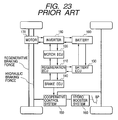
- Fig. 23 shows a conventional hybrid vehicle which comprises a regeneration ECU 110 sending a drive request value to each of the following electronic control units (i.e., ECUs).
- a motor ECU 120 controls a motor 170 via an inverter 180 based on the drive request sent from the regeneration ECU 110.
- the motor 170 drives front wheels of this vehicle.
- a battery ECU 130 monitors a charging condition of a battery 190 equipped in this vehicle.
- a brake ECU 140 performs a cooperative control for the regenerative braking device and the hydraulic braking device.
- the brake ECU 140 sends a control signal to a cooperative control valve system 150 to control the switching of this cooperative control valve system 150.
- a hydro booster system 160 generates a hydraulic braking force in response to a depression force applied on a brake pedal BP by a driver.
- the brake ECU 140 calculates a target vehicle braking force corresponding to a depression amount of the brake pedal BP.
- the target vehicle braking force of this hybrid vehicle is substantially equal to a target braking force of an ordinary vehicle having a hydraulic braking device only.
- the brake ECU 140 calculates a regenerative braking force determined in accordance with the target vehicle braking force.
- the regenerative braking force obtained by the brake ECU 140 is transmitted to the regeneration ECU 110 as a requested regenerative braking force.
- the regeneration ECU 110 causes the motor ECU 120 to perform a regenerative control based on the requested regenerative braking force.
- the regeneration ECU 110 detects an actual regenerative braking force generated by the motor 170.
- the regeneration ECU 110 returns the detected actual regenerative braking force to the brake ECU 140 as a producible regenerative braking force.
- the brake ECU 140 obtains a hydraulic braking force which is obtained by subtracting the producible regenerative braking force from the target vehicle braking force.
- the brake ECU 140 obtains a target W/C pressure corresponding to the hydraulic braking force.
- W/C stands for "wheel cylinder.”
- the brake ECU 140 controls the switching of the cooperative control valve system 150 so that a W/C pressure of each wheel is equalized to the target W/C pressure.
- Fig. 24 shows a schematic arrangement of a hydraulic circuit of this hybrid vehicle.
- the hydro booster system 160 comprises a master cylinder (hereinafter, referred to as "M/C") 161 generating a hydraulic pressure in accordance with a piston stroke, a hydraulic pump 163 supplying a pressurized oil, an accumulator 164 storing the pressurized oil supplied from the hydraulic pump 163, and a regulator 162 adjusting the pressurized oil supplied from the accumulator 164 to the same pressure level as that of the M/C 161 in proportion to a depression force applied on the brake pedal BP.
- a reservoir 165 is provided to supply the oil to the hydraulic pump 163.
- the hydraulic pressure of the regulator 162 is transmitted to each W/C of front right, front left, rear right and rear left wheels via the cooperative control valve system 150.
- the cooperative control valve system 150 comprises a linear solenoid valve SLA which increases the hydraulic pressure and a linear solenoid valve SLR which decreases the hydraulic pressure.
- Each of the linear solenoid valves SLA and SLR is opened or closed in response to a control signal supplied from the brake ECU 140 to adjust the pressure level of each W/C.
- the downstream side of the cooperative control valve system 150 is bifurcated into a front oil passage 166 supplying the oil to the front right W/C and the front left W/C of the front wheels, and a rear oil passage 167 supplying the oil to the rear right W/C and the rear left W/C of the rear wheels.
- the front oil passage 166 comprises a switching solenoid valve SS which is usually kept open under supply of electric power.
- the downstream side of the switching solenoid valve SS is bifurcated into an oil passage 168 supplying the oil to the front left W/C of the front left wheel and an oil passage 169 supplying the oil to the front right W/C of the front right wheel.
- Each of the bifurcated oil passages 168 and 169 has a well-known ABS solenoid valve SABS consisting of a pressure increasing valve SH and a pressure reducing valve SR.
- the rear oil passage 167 has an ABS solenoid valve SABS consisting of a pressure increasing valve SH and a pressure reducing valve SR.
- the rear oil passage 167 has a P& B valve provided at the downstream side of the ABS solenoid valve SABS.
- M/C 161 The hydraulic pressure of M/C 161 is transmitted to the P& B valve and to a stroke simulator SSI generating a pedal stroke in accordance with the depression force applied by the driver. Furthermore, M/C 161 is connected to the front left W/C via a switching solenoid valve SMC1 and to the front right W/C via a switching solenoid valve SMC2.
- the switching solenoid valves SMC1 and SMC2 are usually kept closed under supply of electric power. Accordingly, the front right W/C and the front left W/C receive the regulator pressure in an ordinary condition.
- the regenerative braking force may be sufficient enough to supply all of the required vehicle braking force. In such a case, no hydraulic braking force is required. Accordingly, in the cooperative control valve system 150, the pressure-increasing linear solenoid valve SLA is closed. The switching solenoid valves SMC1 and SMC2 are closed, too. However, when the depression amount of the brake pedal BP is increased, the regenerative braking force may be insufficient to supply all of the required vehicle braking force. In such a case, the hydraulic braking force is required. The linear solenoid valve SLA is opened under the condition where both of the switching solenoid valves SMC1 and SMC2 are closed.
- the regulator pressure is supplied to each W/C.
- requiring the hydraulic braking force in this manner may encounter with a system fail wherein the valve SLA is stuck in the closed position and cannot be opened.
- the solenoid of each valve is turned off.
- the switching solenoid valves SMC1 and SMC2 are opened, and the M/C pressure is transmitted to the front right W/C and to the front left W/C.
- the braking force is obtained in accordance with the depression amount of the brake pedal BP.
- the cooperative control valve system 150 is provided at the downstream side of the hydro booster system 160.
- the switching solenoid valves SMC1 and SMC2 it is necessary to consider the possibility that the cooperative control valve system 150 or the hydro booster system 160 may be damaged. This significantly complicates the circuit arrangement.
- JP 11-048954 A discloses a vehicle braking apparatus and method according to the preamble of claims 1 and 6, respectively.
- the present invention has the object to provide a vehicle braking method and a vehicle braking apparatus for applying a braking force to a vehicle by summing a braking force of a hydraulic braking device and a braking force of an auxiliary braking device, wherein a certain minimum braking force according to law regulations is achieved in reliable, fail-safe manner, independent from the auxiliary braking force.
- This object is solved by a vehicle braking apparatus and a method according to claims 1 and 6 respectably.
- an assigned braking force is obtained by subtracting a minimum braking force of the hydraulic braking device corresponding to the brake pedal input value from the target vehicle braking force.
- a distributive braking force of the hydraulic braking device is obtained by subtracting the braking force of the auxiliary braking device from the assigned braking force.
- the hydraulic braking device is controlled based on a target hydraulic braking force which is a sum of the minimum braking force and the distributive braking force.
- the present invention in attaining the target vehicle braking force, the present invention always utilizes the braking force of the hydraulic braking device.
- the vehicle braking apparatus of the present invention does not require to perform the valve switching operation for activating or deactivating the hydraulic braking device. Accordingly, the vehicle braking apparatus of the present invention can execute the cooperative control without using the conventional cooperative control valve system and the switching solenoid valves.
- the hydraulic circuit can be simplified.
- the "target vehicle braking force” is equivalent to a target braking force of an ordinary vehicle which uses the hydraulic braking device only.
- the "brake pedal input value” is for example a depression force applied on the brake pedal or a stroke length of the brake pedal or a M/C pressure.
- the "minimum braking force of the hydraulic braking device is a hydraulic braking force obtained by a mechanically obtained boost ratio and exceeding a minimum venicle braking force required in accordance with law regulations.
- the "auxiliary braking device” is for example a regenerative braking device, an exhaust braking device, or an engine braking device.
- the "braking force” is used to represent a braking force itself and also conceptually used to encompass similar physical quantities, such as deceleration, which can be identified as being equivalent to the braking force.
- the vehicle braking apparatus of the present invention does not restrict the distributive ratio between the auxiliary braking device and the hydraulic braking device.
- all of the assigned braking force is supplied from the auxiliary braking device when the braking force of the auxiliary braking device is not smaller than the assigned braking force and also preferable that the hydraulic braking force is added as a supplement for filling a lack of braking force when the braking force of the auxiliary braking device is smaller than the assigned braking force.
- the braking force of the auxiliary braking device is supplied as much as possible for obtaining the assigned braking force.
- the hydraulic braking device comprises a M/C and a booster provided at the upstream side of the master cylinder and equipped with a boost ratio changing mechanism.
- the braking control means adjusts the boost ratio of the booster when the braking control means controls the hydraulic braking device.
- the "boost ratio” is defined as a ratio of the booster output to the brake pedal input.
- the vehicle braking apparatus of the present invention does not restrict the mechanism for controlling the boost ratio of the booster. It is however preferable in the vehicle braking apparatus to use the mechanism capable of changing the boost ratio by forcibly changing a pedal input of the booster or by changing a pressure of operation fluid supplied to an operation chamber of a power piston of the booster. Employing such a mechanism makes it possible to provide a simple arrangement for realizing the variable boost ratio.
- the auxiliary braking device is a regenerative braking device.
- the vehicle braking apparatus of the present invention is preferable in effectively utilizing the energy in this kind of vehicles and in easily solving the system failure. If the regenerative efficiency is considered, it is desirable that all of the assigned braking force is supplied from the regenerative braking device when the braking force of the regenerative braking device is not smaller than the assigned braking force and the hydraulic braking force is added as a supplement for filling a lack of braking force when the braking force of the regenerative braking device is smaller than the assigned braking force.
- the vehicle braking method of claim 6 comprises the steps of:
- the minimum braking force of the hydraulic braking device is a hydraulic braking force obtained by a mechanically obtained boost ratio.
- vehicle braking method of the present invention is not limited to the vehicle braking apparatus comprising the above-described various means.
- the vehicle braking apparatus may further comprise :
- an assigned braking force is obtained by subtracting a minimum braking force of the hydraulic braking device corresponding to the brake pedal input value from the target vehicle braking force.
- a distributive braking force of the hydraulic braking device is obtained by subtracting the braking force of the auxiliary braking device from the assigned braking force.
- the hydraulic braking device is controlled based on a target hydraulic braking force which is a sum of the minimum braking force and the distributive braking force.
- the hydraulic braking device when the auxiliary braking device is inoperable, the hydraulic braking device is controlled based on a target hydraulic braking force which is equal to the target vehicle braking force. Accordingly, the present invention always utilizes the braking force of the hydraulic braking device in attaining the target vehicle braking force. Furthermore, when the auxiliary braking device is inoperable, the hydraulic braking device is immediately controlled based on the target hydraulic braking force which is equal to the target vehicle braking force without calculating the assigned braking force or without inputting the braking force of the auxiliary braking force.
- the vehicle braking apparatus of the present invention does not require to perform the valve switching operation for activating or deactivating the hydraulic braking device. Accordingly, the vehicle braking apparatus of the present invention can execute the cooperative control without using the conventional cooperative control valve system and the switching solenoid valves. Furthermore, when the auxiliary braking device is inoperable, the vehicle braking apparatus of the present invention can promptly supply a required braking force by the hydraulic braking device.
- the "inoperable condition of the auxiliary braking device” is for example a failure or damage of a regenerative braking device in a case where this regenerative braking device is employed as the auxiliary braking device of the present invention.
- the "inoperable condition of the auxiliary braking device” includes a fully charged condition of the battery.
- the vehicle braking apparatus of the present invention does not restrict the distributive ratio between the auxiliary braking device and the hydraulic braking device.
- all of the assigned braking force is supplied from the auxiliary braking device when the braking force of the auxiliary braking device is not smaller than the assigned braking force and also preferable that the hydraulic braking force is added as a supplement for filling a lack of braking force when the braking force of the auxiliary braking device is smaller than the assigned braking force.
- the braking force of the auxiliary braking device is supplied as much as possible for obtaining the assigned braking force.
- the hydraulic braking device comprises a M/C and a booster provided at the upstream side of the master cylinder and equipped with a boost ratio changing mechanism.
- the braking control means adjusts the boost ratio of the booster when the braking control means controls the hydraulic braking device.
- the M/C pressure for example, in an ABS non-operating condition of an ABS equipped vehicle.
- the boost ratio of the booster cannot be controlled.
- the vehicle braking apparatus of the present invention does not restrict the mechanism for controlling the boost ratio of the booster. It is however preferable to use the mechanism capable of changing the boost ratio by forcibly changing a pedal input of the booster or by changing a pressure of operation fluid supplied to an operation chamber of a power piston of the booster. Employing such a mechanism makes it possible to provide a simple arrangement for realizing the variable boost ratio.
- the hydraulic braking device of the vehicle braking apparatus of the present invention can be constituted by a check valve provided in a first oil passage connecting a M/C to a W/C for maintaining a W/C pressure at a level not lower than a M/C pressure and brake fluid supply means for supplying a pressure regulated brake fluid to the W/C.
- the braking control means adjusts a pressure level of the brake fluid supplied from the brake fluid supply means to the W/C when the braking control means controls the hydraulic braking device.
- the W/C pressure is always maintained to a level not lower than the M/C pressure by the check valve provided in the first oil passage connecting the M/C to the W/C.
- the check valve operates to maintain the W/C pressure to the level not smaller than the M/C pressure.
- the vehicle braking apparatus of the present invention causes the hydraulic braking device to produce a hydraulic braking force not smaller than a hydraulic braking force generated by the M/C pressure (i.e., minimum braking force). If the braking control means or the brake fluid supply means is failed, the pressure regulated brake fluid will not be supplied to W/C. However, in such a failed condition, the second vehicle braking apparatus of the present invention assures that the hydraulic braking device can supply the minimum braking force.
- the adjusting mechanism for adjusting the pressure of the brake fluid supplied to the W/C is not limited to a specific one.
- the brake fluid supply means comprises a pump for supplying a pressurized brake fluid to the W/C, and a control valve provided in a second oil passage connecting the M/C to the W/C.
- This arrangement is advantageous in that the brake fluid supply means can be simply arranged by using the pump and the control valve.
- the control valve maintains the W/C pressure at a value larger than the M/C pressure by a valve opening pressure.
- the valve opening pressure is variable.
- the braking control means adjusts the valve opening pressure of the control valve to adjust the pressure level of the brake fluid supplied to the W/C.
- the auxiliary braking device is a regenerative braking device. If the regenerative efficiency is considered, it is desirable that all of the assigned braking force is supplied from the regenerative braking device when the braking force of the regenerative braking device is not smaller than the assigned braking force and the hydraulic braking force is added as a supplement for filling a lack of braking force when the braking force of the regenerative braking device is smaller than the assigned braking force.
- the auxiliary braking device when the auxiliary braking device is operable, the steps of obtaining the assigned braking force of obtaining the distributive braking force and of controlling the hydraulic braking device are executed.
- the hydraulic braking device when the auxiliary braking device is inoperable, the hydraulic braking device is controlled based on a target hydraulic braking force which is equal to the target vehicle braking force.
- Application of this embodiment of the vehicle braking method of the present invention is not limited to the above described embodiment of the vehicle braking apparatus.
- the target vehicle braking force corresponding to a brake pedal input value it is preferable to set the target vehicle braking force corresponding the brake pedal input value beforehand, and then obtain an assigned braking force by subtracting a minimum braking force of the hydraulic braking device from the target vehicle braking force.
- the assigned braking force is constant (e.g., 0.2 G) regardless of the brake pedal input, it is preferable to directly obtain the distributive braking force of the hydraulic braking device by using this constant value without setting the target vehicle braking force.
- Fig. 1 is a block diagram showing a system arrangement of a vehicle braking apparatus in accordance with the first embodiment of the present invention.
- Fig. 2 is a diagram showing a hydraulic circuit arrangement for the vehicle braking apparatus in accordance with the first embodiment of the present invention.
- the hybrid vehicle comprises a regeneration ECU 10 sending a drive request value to each of the following control units (i.e., ECUs).
- a motor ECU 20 controls a motor 70 via an inverter 80 in accordance with the drive request value sent from the regeneration ECU 10.
- a battery ECU 30 monitors a charging condition of a battery 90 equipped in this vehicle.
- a brake ECU 40 performs a cooperative control for the regenerative braking device and the hydraulic braking device based on a sensing signal of a depression force sensor 41.
- the sensing signal of the depression force sensor 41 is a depression force applied on the brake pedal BP.
- a vacuum booster 50 generates a hydraulic braking force in response to the depression force applied on the brake pedal BP by a driver.
- a boost ratio of the vacuum booster 50 is controlled in accordance with a control signal sent from the brake ECU 40.
- the motor 70 drives a front right wheel FR and a front left wheel FL.
- the inverter 80 converts the discharge power (i.e., DC power) of the battery 90 into AC power in accordance with a control signal sent from the motor ECU 20.
- the produced AC power is supplied to the motor 70.
- the inverter 80 converts the AC power generated by the motor 70 into charging power (i.e., DC power) in accordance with a control signal sent from the motor ECU 20.
- the hydraulic circuit including M/C 51 and vacuum booster 50 will be explained with reference to Fig. 2 .
- the M/C 51 comprises a M/C piston 54 which is accommodated in an inside space of M/C 51 and is hermetically slidable in the axial direction.
- a return spring 55 is provided in the side space of M/C 51 to resiliently urge the M/C piston 54 in a rearward direction (i.e., in a rightward direction in Fig. 2 ).
- the inside space of M/C 51 is partitioned into a front M/C chamber 51a and a rear M/C chamber 51b.
- the front M/C chamber 51a communicates via a front oil passage 6 with a W/C of the front right wheel FR and a W/C of the front left wheel FL, and also communicates via a rear oil passage 7 with a W/C of the rear right wheel RR and a W/C of the rear left wheel RL.
- the front oil passage 6 is bifurcated into a branch oil passage 8 connected to the W/C of the front left wheel FL and a branch oil passage 9 connected to the W/C of the front right wheel FR.
- a well-known ABS solenoid valve SABS consisting of a pressure increasing valve SH and a pressure reducing valve SR, is provided in each of the branch oil passages 8 and 9.
- the ABS solenoid valve SABS is provided in the rear oil passage 7.
- a reservoir 52 always communicates with the rear M/C chamber 51b.
- the reservoir 52 is connected to or disconnected from the front M/C chamber 51a in accordance with the position of the M/C piston 54. More specifically, the reservoir 52 communicates with the front M/C chamber 51a in an initial condition or in a depressurizing phase. On the other hand, the reservoir 52 is disconnected from the front M/C chamber 51a in other conditions (e.g., in a pressurizing phase or in a pressure holding phase).
- the vacuum booster 50 is provided at the upstream side of the M/C 51.
- the vacuum booster 50 comprises a built-in power piston 56.
- the power piston 56 is accommodated in an inside space of the vacuum booster 50 so as to be hermetically slidable along a large-diameter portion in an axial direction of the vacuum booster 50.
- the power piston 56 partitions the inside space of the vacuum booster 50 into a front booster chamber 50a and a rear booster chamber 50b.
- the front booster chamber 50a always communicates with a low-pressure source R LP (e.g., an intake manifold or a vacuum pump).
- the power piston 56 comprises a pressure regulating valve 57 which is accommodated in a through hole 56d and is slidable in the axial direction.
- a rear end of the pressure regulating valve 57 is connected to a pedal input shaft 58.
- the brake pedal BP is swingably supported by the rear end of the pedal input shaft 58.
- a front end of the pressure regulating valve 57 is connected to a valve plunger 59.
- the valve plunger 59 comprises a shaft portion 59a extending in the axial direction of the through hole 56d and a bent portion 59b extending in a radial direction from the front end of the shaft portion 59a.
- the front end of the bent portion 59b supports one end of a first lever 61 so that the first lever 61 is swingable about the bent portion 59b.
- the other end of the first lever 61 supports one end of a second lever 62 so that the second lever 62 is swingable about the first lever 61.
- the other end of the second lever 62 supports one end of a third lever 63 so that the third lever 63 is swingable about the second lever 62.
- the other end of the third lever 63 is swingably supported by the power piston 56.
- the second lever 62 extends across the central axis of the power piston 56 and swingbly supports a booster output shaft 60.
- the booster output shaft 60 extends along the central axis of the power piston 56.
- the booster output shaft 60 extends in a through hole connecting the front booster chamber 50a to the rear M/C chamber 51b so as to be hermetically slidable in an axial direction.
- a first port 56a communicating with the rear booster chamber 50b, a second port 56b communicating a high-pressure source R HP (e.g., atmosphere), and a third port 56c communicating with the front booster chamber 50a are provided on an inside wall of the through hole 56d of the power piston 56.
- a sub cylinder 65 provided at a front position of the power piston 56, faces to the bent portion 59b of the valve plunger 59.
- the sub cylinder 65 accommodates a reaction force adjusting piston 64 in an inside space thereof so as to be hermetically slidable in the axial direction.
- the inside space of the sub cylinder 65 is partitioned into front and rear chambers by the reaction force adjusting piston 64.
- the front chamber of the sub cylinder 65 communicates with the front booster chamber 50a.
- the rear chamber of the sub cylinder 65 serving as a reaction force adjusting chamber 66, communicates with either the low-pressure source R LP or the high-pressure source R HP via a reaction force adjusting solenoid valve 67.
- a reaction force adjusting plunger 68 integral with the reaction force adjusting piston 64 selectively contacts with or separates from the bent portion 59b of the valve plunger 59.
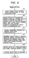
- Fig. 6 is a flowchart showing a brake control repetitively performed by the brake ECU 40 in response to a depression of the brake pedal BP.
- the depression force sensor 41 outputs a pedal depression force, serving as a brake pedal input value, to the brake ECU 40.
- the brake ECU 40 obtains a target vehicle braking force corresponding to the pedal depression force with reference to a map or a table or an equation stored in a memory (refer to step S10).
- an assigned braking force is obtained by subtracting a minimum braking force (later described) of a hydraulic braking device from the target vehicle braking force.
- the assigned braking force thus obtained is transmitted as a requested regenerative braking force to the regeneration ECU 10 (refer to step S20).
- the regeneration ECU 10 causes the motor ECU 20 to perform a regeneration control based on the requested regenerative braking force.
- An actual regenerative braking force produced by the motor 70 is detected.
- the detected actual regenerative braking force is returned as a producible regenerative braking force to the brake ECU 40.
- the brake ECU 40 receives the producible regenerative braking force sent from the regeneration ECU 10 (refer to step S30).
- the brake ECU 40 obtains a target braking force of the hydraulic braking device (i.e., a target hydraulic braking force) which is obtained by subtracting the producible regenerative braking force from the target vehicle braking force (refer to step S40).
- the target hydraulic braking force is equal to a sum of the minimum braking force and a distributive braking force.
- the distributive braking force is equal to a difference between the requested regenerative braking force and the producible regenerative braking force.
- a target M/C pressure corresponding to the target hydraulic braking force is obtained based on a map or a table or an equation stored in the memory (refer to step S50).
- the boost ratio of vacuum booster 50 is controlled by switching the reaction force adjusting solenoid valve 67 in such a manner that the actual M/C pressure (i.e., the pressure in the front M/C chamber 51a) is equalized to the target M/C pressure (refer to step S60). More specifically, the boost ratio control is performed in the following manner.
- the M/C pressure is equal to the W/C pressure during an ordinary braking operation (e.g., an ABS non-operating condition).
- an oil pressure detected by a hydraulic sensor provided somewhere in a path connecting the front M/C chamber 51a to each W/C is compared with the target M/C pressure to obtain a difference.
- a feedback control is performed to eliminate this difference.
- the following description includes a first reaction force mode and a second reaction force mode for the reaction force adjusting solenoid valve 67.
- the reaction force adjusting solenoid valve 67 connects the reaction force adjusting chamber 66 to the low-pressure source R LP (refer to Figs. 2 to 4 ).
- the reaction force adjusting solenoid valve 67 connects the reaction force adjusting chamber 66 to the high-pressure source R HP (refer to Fig. 5 ).
- Fig. 2 shows the initial/ depressurizing state where the brake pedal BP is not depressed or the brake pedal is returning to the initial (i.e., home) position.
- the M/C piston 54 is resiliently urged rearward by the return spring 55.
- the front M/C chamber 51a communicates with the reservoir 52.
- the pressure regulating valve 57 is positioned at an initial position where the first port 56a is connected to the third port 56c while the second port 56b is isolated.
- the front booster chamber 50a and the rear booster chamber 50b are maintained at the low pressure of the low-pressure source R LP . None of the hydraulic braking force and the regenerative braking force are available in this condition.
- Fig. 3 shows the pressurizing state where the brake pedal BP is depressed more than a predetermined amount prior to the holding state.
- the pressure regulating valve 57 is positioned at a pressure-increasing position where the first port 56a is connected to the second port 56b while the third port 56c is isolated.
- the high-pressure source R HP is connected to the rear booster chamber 50b.
- the front booster chamber 50a is isolated from the rear booster chamber 50b.
- the power piston 56 moves forward by a pressure difference between the high-pressure source R HP and the low-pressure source R LP .
- the power piston 56 when moving forward, pushes the M/C piston 54 vial the booster output shaft 60.
- the front M/C chamber 51a is isolated from the reservoir 52.
- the inside pressure of front M/C chamber 51a i.e., M/C pressure
- increases M/C pressure is transmitted to the W/C of each wheel.
- the hydraulic braking force is available.
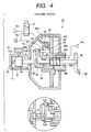
- Fig. 4 shows the holding state where the brake pedal BP is held in a depressed condition.
- a reaction force of the booster output is separated into a reaction force of the power piston and a reaction force of the valve plunger.
- the pedal input shaft 58 is pushed back by the reaction force of the valve plunger.
- the pressure regulating valve 57 is thus shifted to a holding position where the first port 56a, the second port 56b and the third port 56c are isolated from each other.
- the pressure regulating valve 57 is balanced at this holding position. In this condition, the reaction force of the pedal input shaft is equal to the reaction force of the valve plunger.
- Fb represents a booster output
- Fpd represents the reaction force of the power piston
- Fvd represents the reaction force of the valve plunger
- Lp represents the length of a power piston side of the second lever 62
- Lv represents the length of a valve plunger side of the second lever 62
- Fi represents the reaction force of the pedal input shaft.
- the following equations 1 to 3 are established to determine the relationship between the booster output and the reaction force of the input shaft. More specifically, in the first reaction force mode, the boost ratio (Fb/Fi) is substantially determined by Lv and Lp which depend on the mechanical arrangement.
- the boost ratio thus obtained is referred to as “mechanically determined boost ratio.”
- the hydraulic braking force obtained by this boost ratio is referred to as "minimum braking force of hydraulic braking device" which is set to be not smaller than a minimum vehicle braking force required according to law regulations.
- the reaction force adjusting solenoid valve 67 connects the reaction force adjusting chamber 66 to the high-pressure source R HP .
- R HP high-pressure source
- air is introduced into the reaction force adjusting chamber 66.
- the pressure of the reaction force adjusting chamber 66 increases.
- the increased pressure acts on the reaction force adjusting piston 64.
- the reaction force adjusting plunger 68 pushes the valve plunger 59 forward so as to bring it into a balanced condition.
- This balanced condition establishes the following relationship, in which Pc represents a pressure difference between the reaction force adjusting chamber 66 and the front booster chamber 50a and Ac represents an area of the reaction force adjusting piston 64.
- the reaction force of the input shaft becomes small in the second reaction force mode compared with the first reaction force mode.
- the booster ratio is substantially determined by the pressure of the reaction force adjusting chamber 66.
- the boost ratio control of the booster is performed in the following manner.
- the M/C pressure is obtained in accordance with the mechanically determined boost ratio.
- the hydraulic braking device produces the minimum braking force.
- the target M/C pressure corresponding to a pedal depression force may exceed the M/C pressure corresponding to the minimum braking force of the hydraulic braking device.
- the brake ECU 40 adequately selects the first reaction force mode or the second reaction force mode, i.e., adequately switches the reaction force adjusting solenoid valve 67, to feedback controls the actual M/C pressure to the target M/C pressure. With this feedback control, the boost ratio exceeds the mechanically determined boost ratio.
- the M/C pressure is obtained in accordance with this boost ratio and the target hydraulic braking force is attained.
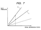
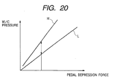
- Fig. 7 is a graph showing the relationship between the pedal depression force and the M/C pressure.
- a straight line L represents the characteristics of the first reaction force mode which is determined beforehand in accordance with the minimum braking force of the hydraulic braking device.
- a straight line H represents the characteristics of the second reaction force mode which is for example determined in accordance with the target vehicle braking force.
- the M/C pressure can be plotted as a point on the straight line L corresponding to the pedal depression force.
- the M/C pressure can be plotted as a point in a region between the straight line L and the straight line H.
- a dotted line represents the characteristics in case of the booster failure in which a pressure difference between the high-pressure source R HP and the low-pressure source R LP becomes 0.
- the boost ratio can be defined as a ratio of the M/C pressure in a normal booster to the M/C pressure in a failed booster.
- Fig. 8 is a graph showing the relationship between the depression time of the brake pedal BP and the vehicle braking force. This graph is drawn based on the following assumption. In the beginning of the depression of the brake pedal BP, the battery 90 is fully charged and therefore no regenerative braking force is produced. Thereafter, due to some amount of discharging, the battery 90 comes to a condition that the regenerative braking force is producible. Then, the battery 90 is again fully charged and no generative force is producible.
- the distributive braking force is obtained by subtracting the producible regenerative braking force from the assigned braking force.
- the boost ratio of the booster is controlled so as to obtain a sum of the distributive braking force thus obtained and the minimum braking force.
- the boost ratio of the booster varies in the range between the straight line H and the straight line L shown in Fig. 7 .
- the producible regenerative braking force is maximized (refer to phase III)
- all of the assigned braking force is supplied from the regenerative braking device.
- the boost ratio of the booster is controlled so as to cause the hydraulic braking device to produce the minimum braking force.
- the boost ratio of the booster agrees with the straight line L shown in Fig. 7 .
- the distributive braking force is obtained by subtracting the producible regenerative braking force from the assigned braking force.
- the boost ratio of the booster is controlled so as to obtain a sum of the distributive braking force thus obtained and the minimum braking force.
- the boost ratio of the booster varies in the range between the straight line H and the straight line L shown in Fig. 7 .
- the depression force sensor 41 of the first embodiment serves as input value detecting means of the present invention.
- the brake ECU 40 serves as target vehicle braking force output means, assigned braking force output means, and brake control means of the present invention.
- the step S 10 represents the processing performed by the target vehicle braking force output means
- the step S20 represents the processing of the assigned braking force output means
- steps S40 to S60 represent the processing of the brake control means.
- the first embodiment has the following effects.
- the second embodiment differs from the first embodiment in that the vacuum booster 50 is replaced by a hydro booster 250. Therefore, components identical with those disclosed in the first embodiment are denoted by same reference numerals. The explanation for these components is omitted in the following explanation.
- Fig. 9 shows a hydraulic circuit arrangement in accordance with the second embodiment of the present invention.
- the hydro booster 250 is provided at the upstream side of M/C 51.
- the hydro booster 250 comprises a built-in power piston 256.
- the power piston 256 is accommodated in an inside space of the hydro booster 250 so as to be hermetically slidable in an axial direction of the hydro booster 250.
- the power piston 256 partitions the inside space of the hydro booster 250 into a front booster chamber 250a and a rear booster chamber 250b.
- the front booster chamber 250a always communicates with a reservoir 52 serving as a low-pressure source.
- the power piston 256 comprises a reaction force piston 254 which is accommodated in a bore 255 and is slidable in the axial direction.
- a pressure regulating valve 257 is integrally formed with the reaction force piston 254.
- the inside space of the bore 255 is separated into a front bore chamber 256a and a rear bore chamber 256b by the reaction force piston 254.
- a rear end of the reaction force piston 254 is connected to a pedal input shaft 258.
- the brake pedal BP is swingably supported by the rear end of the pedal input shaft 258.
- a spring 259 is provided at the front side of the reaction force piston 254.
- a booster output shaft 260 is integrally formed with the power piston 256 and extends forward from the power piston 256.
- the booster output shaft 260 is hermetically slidable in an axial direction in a through hole connecting the front booster chamber 250a to a rear M/C chamber 51b.
- a M/C piston 54 is always brought into contact with the booster output shaft 260.
- a first port 255a, a second port 255b, and a third port 255c are provided on an inside wall of the bore 255.
- the first port 255a always communicates with the front bore chamber 256a.
- a boost ratio adjusting solenoid valve 262 selectively connects or disconnects the first port 255a to or from the rear booster chamber 250b.
- a pressure difference between the first port 255a and the rear booster chamber 250b is limited within a predetermined value by a differential pressure regulating valve 266.
- the brake ECU 40 controls a valve opening pressure of the differential pressure regulating valve 266.
- the second port 255b always communicates with an accumulator 263 which stores a pressurized brake fluid.
- the third port 255c always communicates with both of the front booster chamber 250a and the rear bore chamber 256b.
- a hydraulic pump 264 pressurizes a brake fluid of the reservoir 52 and supplies the pressurized brake fluid to the accumulator 263.
- the second embodiment is similar to the first embodiment in an operation of the hybrid vehicle during a brake pedal operation. Namely, the brake control of the hybrid vehicle is performed in accordance with the flowchart shown in Fig. 6 , although the boost ratio control in the step S60 is performed by the hydro booster 250.
- the following description includes a first output mode and a second output mode for the boost ratio adjusting solenoid valve 262.
- the boost ratio adjusting solenoid valve 262 connects the rear boost chamber 250b to the first port 255a and the front bore chamber 256a (refer to Figs. 9 to 11 ).
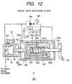
- the boost ratio adjusting solenoid valve 262 connects the rear booster chamber 250b to the accumulator 263 (refer to Fig. 12 ).
- Fig. 9 shows the initial/ depressurizing state where the brake pedal BP is not depressed or the brake pedal is returning to the initial (i.e., home) position.
- the M/C piston 54 is resiliently urged rearward by the return spring 55.
- the front M/C chamber 51a communicates with the reservoir 52.
- the pressure regulating valve 257 is positioned at an initial position where the first port 255a is connected to the third port 255c while the second port 2556b is isolated.
- the front booster chamber 250a and the rear booster chamber 250b are maintained at the low pressure of the reservoir 52. None of the hydraulic braking force and the regenerative braking force are available in this condition.
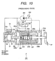
- Fig. 10 shows the pressurizing state where the brake pedal BP is depressed more than a predetermined amount prior to the holding state.
- the pressure regulating valve 257 is positioned at a pressure-increasing position where the first port 255a is connected to the second port 255b while the third port 255c is isolated.
- the accumulator 263, serving as the high-pressure source, is connected to the rear booster chamber 250b.
- the front booster chamber 250a is isolated from the rear booster chamber 250b.
- the power piston 256 moves forward by a pressure difference between the front booster chamber 250a and the rear booster chamber 250b. The power piston 256, when moving forward, pushes the M/C piston 54 vial the booster output shaft 260.
- the front M/C chamber 51a is isolated from the reservoir 52.
- the inside pressure of front M/C chamber 51a i.e., M/C pressure
- M/C pressure increases.
- the increased M/C pressure is transmitted to the W/C of each wheel.
- the hydraulic braking force is available.
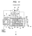
- Fig. 11 shows the holding state where the brake pedal BP is held in a depressed condition.
- the pedal input shaft 258 is pushed back by a reaction force which is produced when the pressure of the front bore chamber 256a (i.e., regulator pressure) acts on the reaction force piston 254.
- the pressure regulating valve 257 is thus shifted to a holding position where the first port 255a, the second port 255b and the third port 255c are isolated from each other.
- the pressure regulating valve 257 is balanced at this holding position.
- Fb a booster output
- Fi the reaction force of the pedal input shaft
- Ap an area of the power piston
- Ar an area of the reaction force piston
- Pr the regulator pressure
- Pp the pressure of the rear booster chamber 250b.
- the following equations are established to determine the relationship between the booster output and the reaction force of the pedal input shaft.
- the boost ratio (Fb/Fi) is substantially determined by Ap and Ar which depend on the mechanical arrangement. Accordingly, the boost ratio thus obtained is referred to as “mechanically determined boost ratio.”
- the hydraulic braking force obtained by this boost ratio is referred to as "minimum braking force of hydraulic braking device" which is set to be not smaller than a minimum vehicle braking force required according to law regulations.
- Fb Fi ⁇ Ap / Ar
- the boost ratio adjusting solenoid valve 262 connects the rear booster chamber 250b to the accumulator 263.
- the pressure of the rear booster chamber 250b increases.
- the pressure of the rear booster chamber 250b is suppressed by the differential pressure regulating valve 266.
- the valve opening pressure of the differential pressure regulating valve 266 restricts a pressure difference between the rear booster chamber 250b and the regulator pressure to a predetermined value.
- Pd represents the valve opening pressure of the differential pressure regulating valve 266.
- the booster output obtained in response to the same reaction force of the pedal input shaft becomes large in the second output mode compared with the first output mode.
- the booster ratio is substantially determined by the valve opening pressure of the differential pressure regulating valve 266.
- the boost ratio increases when the second output mode is employed in the pressurizing state or in the pressurizing state.
- the boost ratio control of the booster is performed in the following manner.
- the M/C pressure is obtained in accordance with the mechanically determined boost ratio.
- the hydraulic braking device produces the minimum braking force.
- the target M/C pressure corresponding to a pedal depression force may exceed the M/C pressure corresponding to the minimum braking force of the hydraulic braking device.
- the brake ECU 40 is set to the second output mode and the valve opening pressure of the differential pressure regulating valve 266 is adequately changed to equalize the actual M/C pressure to the target M/C pressure.
- the boost ratio exceeds the mechanically determined boost ratio.
- the M/C pressure is obtained in accordance with this boost ratio and the target hydraulic braking force is attained.
- valve opening pressure of the differential pressure regulating valve 266 it is preferable to obtain a valve opening pressure corresponding to the target M/C pressure by using a map or a table or an equation which is stored beforehand in a memory.
- the feedback control is performed so as to equalize the valve opening pressure of the differential pressure regulating valve 266 with the obtained valve opening pressure.
- the relationship between the pedal depression force and the M/C pressure is substantially identical with that of the first embodiment shown in the graph of Fig. 7 .
- the straight line L represents the characteristics of the first output mode.
- the region between the straight line L and the straight line H represents the characteristics of the second output mode.
- the M/C pressure is substantially dependent on the mechanically determined boost ratio.
- the M/C pressure is thus determined in proportion to the pedal depression force (refer to the straight line L).
- the boost ratio changes in accordance with the valve opening pressure of the differential pressure regulating valve 266.
- the M/C pressure responsive to the pedal depression force varies in the region between the straight line L and the straight line H.
- the reaction force adjusting solenoid valve 67 may have a holding position for holding the pressure of reaction force adjusting chamber 66 (by isolating the reaction force adjusting chamber 66 from both of the low-pressure source R LP and the high-pressure source R HP ).
- the second embodiment it is possible to omit the differential pressure regulating valve 266 from the hydraulic circuit arrangement. In this case, the feedback control for equalizing the actual M/C pressure to the target M/C pressure is performed by controlling the valve position of the boost ratio adjusting solenoid valve 262.
- the boost ratio variable booster such as the vacuum booster 50 or the hydro booster 250, disclosed in the above-described first and second embodiments makes it possible to realize so-called "variable jumping characteristics.”
- the relationship between a depression force applied on the brake pedal and an attained deceleration is as follows. When the depression force is small (i.e., when the depressing operation of the brake pedal is in a very beginning stage), the deceleration amount increases at a relatively small rate. On the other hand, when the depression force is large (e.g., when the depression amount of the brake pedal reaches a predetermined level), the deceleration amount increases at a relatively large rate.
- the M/C pressure abruptly increases (as if it jumps) when the depression amount of the brake pedal reaches the predetermined level.
- the M/C pressure at this moment is referred to as Pjump.
- the brake stopping distance is dependent on a traveling speed of the vehicle. Even if the applied braking force is the same, the brake stopping distance of the vehicle varies according to its traveling speed.
- Pjump is set to a small value when the vehicle traveling speed is low and is set to a large value when the vehicle traveling speed is high.
- the M/C pressure can be differentiated in accordance with the vehicle traveling speed even when the same depression force is applied on the brake pedal. Thus, it becomes possible to obtain an appropriate braking force considering the vehicle traveling speed.
- the conventional vacuum booster uses a fixed value for Pjump.
- the boost ratio variable booster of the above-described embodiments can flexibly change the value of Pjump by changing the boost ratio.
- the boost ratio variable booster of the above-described embodiments can provide variable jumping characteristics. More specifically, it is possible to increase the boost ratio with increasing vehicle traveling speed. The value of Pjump increases when the vehicle traveling speed is large. Hence, it becomes possible to reduce a difference of the brake stopping distance between a high-speed traveling condition and a low-speed traveling condition.
- boost ratio variable booster makes it possible to realize a so-called buildup function for increasing the M/C pressure in accordance with the depression time of the bake pedal when a constant depression force is continuously applied on the brake pedal.
- the buildup function shortens the brake stopping distance.
- a third embodiment is explained based on the same system arrangement and the same hydraulic circuit arrangement as those of the first embodiment.
- a vehicle braking apparatus of the third embodiment has a system arrangement shown in Fig. 1 .
- a hydraulic circuit arrangement for the vehicle braking apparatus of the third embodiment is shown in Fig. 2 . Therefore, the above-described detailed explanation of the first embodiment with reference to Figs. 1 and 2 is equally applied to the system arrangement and the hydraulic circuit arrangement of the third embodiment.
- Fig. 13 is a flowchart showing a brake control repetitively performed by the brake ECU 40 in response to a depression of the brake pedal BP.
- the depression force sensor 41 outputs a pedal depression force, serving as a brake pedal input value, to the brake ECU 40.
- the brake ECU 40 obtains a target vehicle braking force corresponding to the pedal depression force with reference to a map or a table or an equation stored in a memory (refer to step S110).
- the brake ECU 40 checks wether or not the regenerative braking device is operable (refer to step S120). More specifically, the brake ECU 40 requests the regeneration ECU 10 to collect information relating to the operation of the motor 70 as well as information relating to the charging condition of the battery 90.
- the regeneration ECU 10 inputs the information relating to the operation of the motor 70 from the motor ECU 20 and also inputs the information relating to the charging condition of the battery 90 from the battery ECU 30.
- the regeneration ECU 10 sends the collected information to the brake ECU 40.
- the brake ECU 40 Based on the information relating to the operation of the motor 70, the brake ECU 40 makes a judgement as to whether the motor 70 can operate normally or whether input and output lines of the motor 70 are broken or short-circuited.
- the brake ECU 40 makes a judgement as to whether the battery 90 is fully charged.
- step S120 When it is judged in the step S120 that the regenerative braking device is operable (i.e., YES in step S120), the brake ECU 40 proceeds to a step S130. Namely, the brake ECU 40 proceeds to the step S130 only when the following conditions are satisfied; the motor 70 operates normally, the input and output lines of the motor 70 are not broken or not short-circuited, and the battery 90 is not fully charged.
- step S130 an assigned braking force is obtained by subtracting a minimum braking force (later described) of a hydraulic braking device from the target vehicle braking force obtained in the step S110. The assigned braking force thus obtained is transmitted as a requested regenerative braking force to the regeneration ECU 10 (refer to step S130).
- the regeneration ECU 10 causes the motor ECU 20 to perform a regeneration control based on the requested regenerative braking force.
- An actual regenerative braking force produced by the motor 70 is detected.
- the detected actual regenerative braking force is returned as a producible regenerative braking force to the brake ECU 40.
- the brake ECU 40 receives the producible regenerative braking force sent from the regeneration ECU 10 (refer to step S 140).
- the brake ECU 40 obtains a target braking force of the hydraulic braking device (i.e., a target hydraulic braking force) which is obtained by subtracting the producible regenerative braking force from the target vehicle braking force (refer to step S150).
- the target hydraulic braking force is equal to a sum of the minimum braking force and a distributive braking force.
- the distributive braking force is equal to a difference between the requested regenerative braking force and the producible regenerative braking force. Then, the control flow proceeds to step S160.
- step S120 when it is judged in the step S120 that the regenerative braking device is inoperable (i.e., NO in step S120), the control flow proceeds to step S 155.
- the brake ECU 40 proceeds to the step S155 when the following conditions are satisfied; the motor 70 does not operate normally, or the input and output lines of the motor 70 are broken or short-circuited, or the battery 90 is fully charged.
- the target vehicle braking force obtained in the step S110 is output as a target hydraulic braking force.
- the control flow proceeds to the step S160.
- the regenerative braking force is regarded as being equal to zero when the regenerative braking device is inoperable. In such a case, all of the target vehicle braking force is supplied from the hydraulic braking device.
- a target M/C pressure corresponding to the target hydraulic braking force of the step S150 or S155 is obtained based on a map or a table or an equation stored in the memory (refer to step S160).
- the boost ratio of vacuum booster 50 is controlled by switching the reaction force adjusting solenoid valve 67 in such a manner that the actual M/C pressure (i.e., the pressure in the front M/C chamber 51a) is equalized to the target M/C pressure (refer to step S170). More specifically, the boost ratio control is performed in the following manner.
- the M/C pressure is equal to the W/C pressure during an ordinary braking operation (e.g., an ABS non-operating condition).
- an oil pressure detected by a hydraulic sensor provided somewhere in a path connecting the front M/C chamber 51a to each W/C is compared with the target M/C pressure to obtain a difference.
- a feedback control is performed to eliminate this difference.
- step S120 it may be possible to omit the judgement of step S120 so that the control flow directly proceeds from step 110 to step 130.
- the inoperable condition of motor 70 is detectable in the step S140 because the producible regenerative braking force received from the regeneration ECU 10 becomes zero in step S140.
- the target vehicle braking force agrees with the target hydraulic braking force in the step S150.
- step S155 all of the target vehicle braking force is supplied from the hydraulic braking device.
- prosecuting all of the steps S130, S140, and S150 takes a significant time. The overall processing cannot be accomplished promptly.
- step S120 makes it possible to promptly respond to an inoperable condition of the regenerative braking device.
- the control flow directly proceeds to the step S155 to equalize the target hydraulic braking force with the target vehicle braking force.
- the vacuum booster 50 operates in the same manner as that explained in the first embodiment. Therefore, the above-described detailed explanation of the first embodiment with reference to Figs. 2 to 5 is equally applied to the vacuum booster 50 of the third embodiment.
- the boost ratio control of the booster is performed in the following manner.
- the M/C pressure is obtained in accordance with the mechanically determined boost ratio.
- the hydraulic braking device produces the minimum braking force.
- the target M/C pressure corresponding to a pedal depression force may exceed the M/C pressure corresponding to the minimum braking force of the hydraulic braking device.
- the brake ECU 40 adequately selects the first reaction force mode or the second reaction force mode, i.e., adequately switches the reaction force adjusting solenoid valve 67, to feedback controls the actual M/C pressure to the target M/C pressure. With this feedback control, the boost ratio exceeds the mechanically determined boost ratio.
- the M/C pressure is obtained in accordance with this boost ratio and the target hydraulic braking force is attained.
- the target M/C pressure agrees with the target vehicle braking force.
- the M/C pressure is represented by a point on the straight line H corresponding to its pedal depression force.
- the judgement result becomes YES in step S 120 of Fig.13 .
- the producible regenerative braking force gradually increases (refer to phase II).
- the distributive braking force is obtained by subtracting the producible regenerative braking force from the assigned braking force.
- the boost ratio of the booster is controlled so as to obtain a sum of the distributive braking force thus obtained and the minimum braking force.
- the boost ratio of the booster varies in the range between the straight line H and the straight line L shown in Fig. 7 .
- all of the assigned braking force is supplied from the regenerative braking device.
- the boost ratio of the booster is controlled so as to cause the hydraulic braking device to produce the minimum braking force.
- the boost ratio of the booster agrees with the straight line L shown in Fig. 7 .
- the producible regenerative braking force gradually decreases (refer to phase IV).
- the distributive braking force is obtained by subtracting the producible regenerative braking force from the assigned braking force.
- the boost ratio of the booster is controlled so as to obtain a sum of the distributive braking force thus obtained and the minimum braking force.
- the boost ratio of the booster varies in the range between the straight line H and the straight line L shown in Fig. 7 .
- Fig. 14 is a graph showing the relationship between the depression time of the brake pedal BP and the vehicle braking force. This graph is drawn based on the assumption that no regenerative braking force is available all the time due to failure or damage of the motor 70. In the graph of Fig. 14 , the generative braking force is not available all the time from the beginning of the depression of the brake pedal BP. Thus, the judgement result always becomes NO in step S 120 of Fig. 13 .
- the boost ratio of the booster is controlled in such a manner that all of the target vehicle braking force is supplied from the hydraulic braking device. In this case, the boost ratio of the booster agrees with the straight line H shown in Fig. 7 .
- the depression force sensor 41 of this embodiment serves as input value detecting means of the present invention.
- the brake ECU 40 serves as target vehicle braking force output means, assigned braking force output means, auxiliary brake operability judging means, and brake control means of the present invention.
- the step S110 represents the processing performed by the target vehicle braking force output means
- the step S120 represents the processing of the auxiliary brake operability judging means
- the step S130 represents the processing of the assigned braking force output means
- steps S150, S155, S160, and S170 represent the processing of the brake control means.
- the third embodiment has the following effects.
- the fourth embodiment differs from the third embodiment in that the vacuum booster 50 is replaced by the hydro booster 250 disclosed in the second embodiment.
- the hydro booster 250 operates in the same manner as that explained in the second embodiment. Therefore, the above-described detailed explanation of the second embodiment with reference to Figs. 9 to 12 is equally applied to the hydro booster 250 of the fourth embodiment.
- the operation of the hybrid vehicle during a brake pedal operation in the fourth embodiment is performed in the same manner as in the third embodiment. Namely, the brake control of the hybrid vehicle of the fourth embodiment is performed in accordance with the flowchart shown in Fig. 13 , although the boost ratio control in the step S170 is performed by the hydro booster 250.
- the boost ratio control of the booster is performed in the following manner.
- the M/C pressure is obtained in accordance with the mechanically determined boost ratio.
- the hydraulic braking device produces the minimum braking force.
- the target M/C pressure corresponding to a pedal depression force may exceed the M/C pressure corresponding to the minimum braking force of the hydraulic braking device.
- the brake ECU 40 is set to the second output mode and the valve opening pressure of the differential pressure regulating valve 266 is adequately changed to equalize the actual M/C pressure to the target M/C pressure.
- the boost ratio exceeds the mechanically determined boost ratio.
- the M/C pressure is obtained in accordance with this boost ratio and the target hydraulic braking force is attained.
- valve opening pressure of the differential pressure regulating valve 266 it is preferable to obtain a valve opening pressure corresponding to the target M/C pressure by using a map or a table or an equation which is stored beforehand in a memory.
- the feedback control is performed so as to equalize the valve opening pressure of the differential pressure regulating valve 266 with the obtained valve opening pressure.
- the relationship between the pedal depression force and the M/C pressure is substantially identical with that of the first embodiment shown in the graph of Fig. 7 .
- the straight line L represents the characteristics of the first output mode.
- the region between the straight line L and the straight line H represents the characteristics of the second output mode.
- the M/C pressure is substantially dependent on the mechanically determined boost ratio.
- the M/C pressure is thus determined in proportion to the pedal depression force (refer to the straight line L).
- the boost ratio changes in accordance with the valve opening pressure of the differential pressure regulating valve 266.
- the M/C pressure responsive to the pedal depression force varies in the region between the straight line L and the straight line H.
- the relationship between the depression time of the brake pedal BP and the vehicle braking force is substantially identical with that of the third embodiment shown in the graphs of Figs. 8 and 14 . Therefore, the detailed explanation of the graphs of Figs. 8 and 14 in the third embodiment is equally applied to the fourth embodiment. Thus, the fourth embodiment brings substantially the same effects as those of the third embodiment.
- Fig. 15 is a block diagram showing a system arrangement of a vehicle braking apparatus in accordance with a fifth embodiment of the present invention.
- Fig. 16 is a diagram showing a hydraulic circuit arrangement for the vehicle braking apparatus in accordance with the fifth embodiment of the present invention.
- the hybrid vehicle of the fifth embodiment is similar to that of the first embodiment but different in its detailed system arrangement that the vacuum booster 50 is replaced by a first check valve 352 maintaining the W/C pressure at a level not lower than the M/C pressure and a brake fluid supply section 360 controlling a brake fluid pressure transmitted to the W/C based on a control signal sent from the brake ECU 40.
- the same components as those disclosed in the first embodiment are denoted by the same reference numerals and will not be explained.
- a M/C 351 comprises a M/C piston 351a which in slidable against a resilient force of a return spring 351b when the brake pedal BP is depressed.
- the M/C 351 produces a M/C pressure corresponding to a depression force applied on the brake pedal BP. If necessary, a booster can be provided in the M/C 351.
- the M/C 351 is connected to a W/C of each wheel via an oil passage 306.
- the first check valve 352 and a W/C linear valve 353 are connected in parallel with each other in the oil passage 306.
- the first check valve 352 is provided in a first oil passage 306a connecting the M/C 351 to the W/C of each wheel.
- the first check valve 352 allows the brake fluid to flow from the M/C 351 to the W/C of each wheel.
- the first check valve 352 maintains the W/C pressure at a level not lower than the M/C pressure.
- the W/C linear valve 353 is provided in a second oil passage 306b connecting the M/C 351 to the W/C of each wheel.
- the W/C linear valve 353 is selectively switched between two positions in response to supply of electric power. When no electric power is supplied, the W/C linear valve 353 always opens the second oil passage 306b. When electric power is supplied, the W/C linear valve 353 opens the second oil passage 306b only when it receives a predetermined valve opening pressure. In other words, the W/C linear valve 353 acts as a differential pressure regulating valve under supply of electric power (refer to Fig. 16 ). The brake ECU 40 adjusts the valve opening pressure of the W/C linear valve 353 serving as the differential pressure regulating valve.
- An oil pressure sensor 358 is provided between the M/C 351 and the W/C linear valve 353 for detecting the M/C pressure in the oil passage 306.
- the M/C pressure detected by the oil pressure sensor 358 is sent to the brake ECU 40.
- An outlet port of a hydraulic pump 354 is connected to the oil passage 206 between the W/C linear valve 353 and the W/C of each wheel.
- the hydraulic pump 354 is activated or deactivated in accordance with a control signal sent from the brake ECU 40.
- the hydraulic pump 354 when activated, pumps the brake fluid from the reservoir 355 and supplies pressurized brake fluid to the W/C of each wheel.
- the hydraulic pump 354 and the W/C linear valve 353 cooperatively constitute the brake fluid supply section 360.
- the reservoir 355 is provided separately from a M/C reservoir (not shown).
- An oil passage 307 connects an intermediate point of the W/C linear valve 353 and the M/C 351 to the reservoir 355.
- a stroke simulator valve 356 and a second check valve 357 are connected in parallel with each other in the oil passage 307.
- the stroke simulator valve 356 disconnects the M/C 351 from the reservoir 355.
- opening and closing of the stroke simulator valve 356 is switched at a predetermined valve opening pressure.
- the stroke simulator valve 356 acts as a differential pressure regulating valve under supply of electric power (refer to Fig. 16 ).
- the brake ECU 40 adjusts the valve opening pressure of the stroke simulator valve 356 serving as the differential pressure regulating valve.
- the valve opening pressure of the stroke simulator valve 356 should be determined considering the depression feeling of the brake pedal BP. For example, it is preferable to obtain a valve opening pressure of the stroke simulator valve 356 corresponding to a M/C pressure detected by the oil pressure sensor 358 with reference to a map, or a table or an equation which is stored beforehand in a memory.
- the M/C piston 351a returns to the home position by the resilient force of the return spring 351b.
- the brake fluid of the reservoir 355 is supplied via the second check valve 357 to the M/C 351 until the brake fluid amount in the M/C 351 restores to an initial amount.
- the oil amount flowing into the reservoir 355 is kept at a constant value.
- Fig. 17 is a cross-sectional view showing an example of the W/C linear valve 353.
- the W/C linear valve 353 chiefly consists of a guide 531, a seat valve 532, a coil 533, a plunger 536, and a shaft 537.
- the guide 531 made of a magnetic member, has a vertical through hole 531a extending along an axis of a cylindrical body thereof. Furthermore, the guide 531 has a lateral through hole 531b extending in a direction substantially normal to the vertical through hole 531a.
- the seat valve 532 is press fitted into the vertical through hole 531a so as to be positioned lower than the lateral through hole 531b.
- the seat valve 532 is a cylindrical body having a through hole 532a extending in the axis direction thereof.
- the coil 533 serving as a solenoid is housed in a yoke 534 positioned above the guide 531.
- the coil 533 is electrically connected to the brake ECU 40.
- the brake ECU 40 selectively activates or deactivates the coil 533 and controls a current amount flowing across the coil 533.
- a sleeve 535 made of a non-magnetic member, is disposed inside the coil 533.
- the plunger 536 is a movable iron core accommodated in an side space of the sleeve 535 so as to be slidable in the axial direction.
- a shaft 537, made of a non-magnetic member, is caulked into an axial bore of the plunger 536.
- the plunger 536 and the shaft 537 are integrally slidable in the axial direction.
- the shaft 537 has a valve body 537a opposing to a seat surface 532b of the seat valve 532. Furthermore, the shaft 537 has a flange 537b.
- a spring 538 is interposed between the flange 537b and the seat valve 532. The spring 538 resiliently urges the shaft 537 and the plunger 536 upward.
- the vertical through hole 531a can communicate with the lateral through hole 531b via the seat valve 532, or via the first check valve 352 accommodated in the W/C linear valve 353.
- the W/C linear valve 353 communicates with the W/C of each wheel and W/C 51.
- the vertical through hole 531a of the guide 531 has a lower opening communicating with the W/C of each wheel.
- the lateral through hole 531b of the guide 531 communicates with the M/C 351.
- the valve body 537a is separated upward from the seat surface 532b by the resilient force of the spring 538.
- the W/C linear valve 353 is in an opened condition (i.e., normal opened condition).
- the coil 533 When electric power is supplied to the coil 533, the coil 533 generates an attraction force in accordance with a current amount. With this attraction force, the guide 531 attracts the plunger 536.
- the first check valve 352 allows the brake fluid to flow from the M/C 351 to the W/C when the M/C pressure is higher than the W/C pressure.
- the first check valve 352 prevents the brake fluid from flowing from the W/C to the M/C 351 when the M/C pressure is lower than the W/C pressure. In the latter case, the brake fluid flows from the W/C to the M/C 351 via the seat valve 532.
- Fig. 18 is a cross-sectional view showing an example of the stroke simulator valve 356.
- the stroke simulator valve 356 chiefly consists of a guide 561, a seat valve 562, a coil 563, a plunger 566, and a shaft 567.
- the guide 561, made of a non-magnetic member, has a vertical through hole 561a extending along an axis of a cylindrical body thereof. Furthermore, the guide 561 has a lateral through hole 561b extending in a direction substantially normal to the vertical through hole 561a.
- the seat valve 562 is press fitted into the vertical through hole 561a so as to be positioned lower than the lateral through hole 561b.
- the seat valve 562 is a cylindrical body having a through hole 562a extending in the axis direction thereof.
- the coil 563 serving as a solenoid is housed in a yoke 564 positioned above the guide 561.
- the coil 563 is electrically connected to the brake ECU 40.
- the brake ECU 40 selectively activates or deactivates the coil 563 and controls a current flowing across the coil 563.
- a sleeve 565 made of a non-magnetic member, is disposed inside the coil 563.
- the plunger 566 is a movable iron core accommodated in an side space of the sleeve 565 so as to be slidable in the axial direction.
- a core stator 569, made of a magnetic member, is disposed above the plunger 566.
- a spring 568 is interposed between the core stator 569 and the plunger 566.
- a shaft 567 made of a non-magnetic member, is caulked into an axial bore of the plunger 566.
- the plunger 566 and the shaft 567 are integrally slidable in the axial direction.
- the shaft 567 has a valve body 567a opposing to a seat surface 562b of the seat valve 562.
- the spring 568 resiliently urges the shaft 567 and the plunger 566 downward.
- the vertical through hole 561a can communicate with the lateral through hole 561b via the seat valve 562, or via the second check valve 357 accommodated in the stroke simulator valve 356.
- the stroke simulator valve 356 communicates with the W/C of each wheel and W/C 351.
- the vertical through hole 561a of the guide 561 has a lower opening communicating with the M/C 351.
- the lateral through hole 561b of the guide 561 communicates with the reservoir 355.
- the stroke simulator valve 356 is in a closed condition (i.e., normal opened condition).
- the coil 563 When electric power is supplied to the coil 563, the coil 563 generates an attraction force in accordance with a current amount. With this attraction force, the core stator 569 attracts the plunger 566.
- the valve body 567a is stopped at a position where the attraction force is balanced with the resilient force of the spring 568.
- the second check valve 357 allows the brake fluid to flow from the reservoir 355 to the M/C 351 when the reservoir pressure is higher than the M/C pressure.
- the second check valve 357 prevents the brake fluid from flowing from the M/C 351 to the reservoir 355 when the reservoir pressure is lower than the M/C pressure. In the latter case, the brake fluid flows from the M/C 351 to the reservoir 355 via the seat valve 562.
- Fig. 19 is a flowchart showing a brake control repetitively performed by the brake ECU 40 in response to a depression of the brake pedal BP.
- the vehicle is cruising (i.e., when the brake pedal BP is not depressed)
- no electric power is supplied to the W/C linear valve 353 and the stroke simulator valve 356.
- the brake pedal BP is depressed, electric power is supplied to the W/C linear valve 353 and the stroke simulator valve 356 each acting as a differential pressure regulating valve (refer to Fig. 16 ).
- the depression force sensor 41 When the driver depresses the brake pedal BP, the depression force sensor 41 outputs a pedal depression force, serving as a brake pedal input value, to the brake ECU 40.
- the brake ECU 40 obtains a target vehicle braking force corresponding to the pedal depression force with reference to a map or a table or an equation stored in a memory, and inputs the M/C pressure from the oil pressure sensor 358 (refer to step S210).
- step S220 the brake ECU 40 checks wether or not the regenerative braking device is operable (refer to step S220).
- the judgement of step S220 is performed in the same manner as in the step S120 of the third embodiment. Therefore, the processing in the step S220 will not be explained in detail.
- the brake ECU 40 judges that the regenerative braking device is operable (i.e., YES in S220)
- the brake ECU 40 obtains an assigned braking force by subtracting a braking force generated by the M/C pressure (i.e., a minimum braking force of the hydraulic braking device) from the target vehicle braking force obtained in the step S210.
- the assigned braking force thus obtained is transmitted as a requested regenerative braking force to the regeneration ECU 10 (refer to step S230).
- the regeneration ECU 10 causes the motor ECU 20 to perform a regeneration control based on the requested regenerative braking force.
- An actual regenerative braking force produced by the motor 70 is detected.
- the detected actual regenerative braking force is returned as a producible regenerative braking force to the brake ECU 40.
- the brake ECU 40 receives the producible regenerative braking force sent from the regeneration ECU 10 (refer to step S240).
- the brake ECU 40 obtains a target braking force of the hydraulic braking device (i.e., a target hydraulic braking force) which is obtained by subtracting the producible regenerative braking force from the target vehicle braking force (refer to step S250).
- a target hydraulic braking force is equal to a sum of the braking force generated by the M/C pressure and a distributive braking force.
- the distributive braking force is equal to a difference between the requested regenerative braking force and the producible regenerative braking force. Then, the control flow proceeds to step S260.
- step S220 when it is judged in the step S220 that the regenerative braking device is inoperable (i.e., NO in step S220), the control flow proceeds to step S255.
- step S255 the target vehicle braking force obtained in the step S210 is output as a target hydraulic braking force. Thereafter, the control flow proceeds to the step S260.
- the regenerative braking force is regarded as being equal to zero when the regenerative braking device is inoperable. In such a case, all of the target vehicle braking force is supplied from the hydraulic braking device.
- a target W/C pressure corresponding to the target hydraulic braking force of the step S250 or S255 is obtained based on a map or a table or an equation stored in the memory (refer to step S260).
- the valve opening pressure of the W/C linear valve 353 and the hydraulic pump 354 are controlled in such a manner that the actual W/C pressure is equalized to the target W/C pressure (refer to step S270).
- the valve opening pressure is set to be equal to a value obtained by subtracting the M/C pressure from the target W/C pressure.
- step S220 To detect the operability of the regenerative braking device, it may be possible to omit the judgement of step S220 so that the control flow directly proceeds from step 210 to step 230. In this case, like the processing of step S255, it is possible to supply all of the target vehicle braking force from the hydraulic braking device. However, prosecuting all of the steps S230, S240, and S250 takes a significant time. The overall processing cannot be accomplished promptly. On the contrary, providing the step S220 makes it possible to promptly respond to an inoperable condition of the regenerative braking device.
- the brake ECU 40 deactivates the M/C linear valve 353 and the stroke simulator valve 56. Namely, no electric power is supplied to the M/C linear valve 353 and the stroke simulator valve 356.
- the M/C linear valve 353 is kept opened, while the stroke simulator valve 356 is closed.
- the W/C pressure is equalized to the M/C pressure.
- the M/C pressure decreases and the W/C pressure decreases correspondingly.
- the stroke simulator valve 356 is closed, the M/C 351 is isolated from the reservoir 355. It is possible to prevent the brake pedal BP from causing a useless stroke.
- the conventional system shown in Fig. 24 always supplies the oil to the stroke simulator SSI. It is therefore necessary, in case of failure, to supply the oil to both of the W/C and the stroke simulator SSI.
- the relationship between the deceleration and the depression force as well as the relationship between the deceleration and the pedal stroke are differentiated from the normal ones.
- the relationship between the deceleration and the pedal stroke remains unchanged.
- the W/C linear valve 353 will not be switched from the activated condition to the deactivated condition. Even in such a case, the first check valve 352 is surely opened evert time the M/C pressure exceeds the W/C pressure in response to the depression of the brake pedal BP. Thus, the W/C pressure is equalized to the M/C pressure.
- the hydraulic braking device can apply the minimum braking force to the vehicle, thereby assuring the fail safe. In this condition, the W/C pressure does not reduce after the brake pedal BP is released. It is however not problem from the view point of the fail safe.
- the presence of the first check valve 352 assures the fail safe mechanism for applying the minimum braking force to the vehicle.
- Fig. 20 is a graph showing the relationship between the pedal depression force and the W/C pressure.
- the valve opening pressure control of the W/C linear valve 353 in the step S270 shown in Fig. 19 is performed in the following manner.
- the brake ECU 40 equalizes the valve opening pressure to a minimum value (i.e., zero).
- the relationship between the pedal depression force and the W/C pressure is represented by the straight line L shown in Fig. 20 .
- the straight line L represents the characteristics of the minimum braking force of the hydraulic braking device.
- the minimum braking force of hydraulic braking device is set to be not smaller than a minimum vehicle braking force required according to law regulations.
- the producible regenerative braking force is a minimum value (i.e., zero)
- the brake ECU 40 sets the valve opening pressure so that the relationship between the pedal depression force and the W/C pressure is represented by a straight line H shown in Fig. 20 .
- the braking force of the hydraulic braking device is equalized to the target vehicle braking force.
- the brake ECU 40 sets the valve opening pressure so that the relationship between the pedal depression force and the W/C pressure exists somewhere in a region between the straight line L and the straight line H shown in Fig. 20 .
- the relationship between the depression time of the brake pedal BP and the vehicle braking force is substantially identical with that of the third embodiment shown in the graphs of Figs. 8 and 14 .
- the producible regenerative braking force gradually increases (refer to phase II).
- the distributive braking force is obtained by subtracting the producible regenerative braking force from the assigned braking force.
- the valve opening pressure is controlled so as to correspond to the distributive braking force thus obtained.
- the W/C pressure varies in the range between the straight line H and the straight line L shown in Fig. 20 .
- the valve opening pressure is controlled so as to be zero. In this case, the W/C pressure agrees with the M/C pressure.
- the W/C pressure is represented by the straight line L shown in Fig. 20 .
- the producible regenerative braking force gradually decreases (refer to phase IV).
- the distributive braking force is obtained by subtracting the producible regenerative braking force from the assigned braking force.
- the valve opening pressure is controlled so as to correspond to the distributive braking force thus obtained.
- the W/C pressure varies in the range between the straight line H and the straight line L shown in Fig. 20 .
- the generative braking force is not available all the time from the beginning of the depression of the brake pedal BP.
- the judgement result always becomes NO in step S220 of Fig.19 .
- the valve opening pressure of the W/C linear valve is controlled in such a manner that all of the target vehicle braking force is supplied from the hydraulic braking device. In this case, the W/C pressure agrees with the straight line H shown in Fig. 20 .
- the first check valve 352 serves as check valve of the present invention.
- the hydraulic pump 354 serves as pump of the present invention.
- the W/C linear valve 353 serves as the control valve of the present invention.
- the depression force sensor 41 serves as input value detecting means of the present invention.
- the brake ECU 40 serves as target vehicle braking force output means, assigned braking force output means, auxiliary brake operability judging means, and brake control means of the present invention.
- step S210 represents the processing performed by the target vehicle braking force output means
- step S220 represents the processing of the auxiliary brake operability judging means
- step S230 represents the processing of the assigned braking force output means
- steps S250, S255, S260 and S270 represent the processing of the brake control means.
- the fifth embodiment has the following effects.
- the brake ECU 40 obtains the information relating to the operability of the regenerative braking device from the regeneration ECU 10 and performs the judgement in the step S120 of Fig. 13 or in the step S220 of Fig. 19 .
- the brake ECU 40 it is possible for the brake ECU 40 to check the operating condition of the motor 70 by monitoring a current value or a voltage value of the motor 70.
- the brake ECU 40 it is possible for the brake ECU 40 to check the breakage and/or short-circuit of the communication lines or disconnection of the connectors through monitoring signals of monitoring lines connecting the regeneration ECU 10 to respective ECUs 20, 30 and 40.
- the fully charged condition of the battery is regarded as one aspect of the inoperable condition of the regenerative braking device.
- the inoperable condition of the regenerative braking device is detected only when the regenerative braking device is failed or damaged.
- the maximum boost ratio of the booster is the boost ratio in the second reaction force mode, i.e., the boost ratio in the condition where the reaction force adjusting solenoid valve 67 connects the reaction force adjusting chamber 66 to the high-pressure source R HP .
- This boost ratio is equalized to the boost ratio for attaining all of the target vehicle braking force by the hydraulic braking device.
- the above-described fifth embodiment can be modified to employ a hydraulic circuit arrangement shown in Fig. 21 .
- the hydraulic circuit arrangement shown in Fig. 21 differs from the circuit arrangement shown in Fig. 16 in that the second oil passage 306b and the W/C linear valve 353 are omitted and, instead, another oil passage 308 and a W/C linear valve 453 (normal close type) are provided.
- the oil passage 308 extends from the first check valve 352 to the reservoir 355.
- the W/C linear valve 453 is provided in the oil passage 308.
- the brake control is performed in the same manner as in the fifth embodiment.
- the valve opening pressure control in the step S270 of Fig. 19 is performed in the following manner.
- the valve opening pressure of the W/C linear valve 453 is equalized to zero so that the W/C pressure agrees with the M/C pressure.
- the valve opening pressure of the W/C linear valve 453 is equalized to the maximum value so that the hydraulic braking pressure agrees with the target vehicle braking force.
- the valve opening pressure of the W/C linear valve 453 is set to be a value between the minimum value and the maximum value.
- the sixth embodiment is explained based on the same system arrangement and the same hydraulic circuit arrangement as those of the fifth embodiment. Namely, a vehicle braking apparatus of the sixth embodiment has a system arrangement shown in Fig. 15 . A hydraulic circuit arrangement for the vehicle braking apparatus of the sixth embodiment is shown in Fig. 16 . Therefore, the above-described detailed explanation of the fifth embodiment with reference to Figs. 15 to 18 is equally applied to the system arrangement and the hydraulic circuit arrangement of the sixth embodiment.
- Fig. 22 is a flowchart showing a brake control repetitively performed by the brake ECU 40 in response to a depression of the brake pedal BP.
- the vehicle is cruising (i.e., when the brake pedal BP is not depressed)
- no electric power is supplied to the W/C linear valve 353 and the stroke simulator valve 356.
- the brake pedal BP is depressed, electric power is supplied to the W/C linear valve 353 and the stroke simulator valve 356 each acting as a differential pressure regulating valve (refer to Fig. 16 ).
- the depression force sensor 41 When the driver depresses the brake pedal BP, the depression force sensor 41 outputs a pedal depression force, serving as a brake pedal input value, to the brake ECU 40.
- the brake ECU 40 obtains a target vehicle braking force corresponding to the pedal depression force with reference to a map or a table or an equation stored in a memory, and inputs the M/C pressure from the oil pressure sensor 358 (refer to step S310).
- an assigned braking force is obtained by subtracting a braking force generated by the M/C pressure (i.e., a minimum braking force of the hydraulic braking device) from the target vehicle braking force.
- the assigned braking force thus obtained is transmitted as a requested regenerative braking force to the regeneration ECU 10 (refer to step S320).
- the regeneration ECU 10 causes the motor ECU 20 to perform a regeneration control based on the requested regenerative braking force.
- An actual regenerative braking force produced by the motor 70 is detected.
- the detected actual regenerative braking force is returned as a producible regenerative braking force to the brake ECU 40.
- the brake ECU 40 receives the producible regenerative braking force sent from the regeneration ECU 10 (refer to step S330).
- the brake ECU 40 obtains a target braking force of the hydraulic braking device (i.e., a target hydraulic braking force) which is obtained by subtracting the producible regenerative braking force from the target vehicle braking force (refer to step S340).
- the target hydraulic braking force is equal to a sum of the braking force generated by the M/C pressure and a distributive braking force.
- the distributive braking force is equal to a difference between the requested regenerative braking force and the producible regenerative braking force.
- a target M/C pressure corresponding to the target hydraulic braking force is obtained based on a map or a table or an equation stored in the memory (refer to step S350).
- the valve opening pressure of the M/C linear valve 353 and the hydraulic pump 354 are controlled in such a manner that the actual W/C pressure is equalized to the target W/C pressure (refer to step S360).
- the valve opening pressure is set to be equal to a value obtained by subtracting the M/C pressure from the target W/C pressure.
- the brake ECU 40 deactivates the M/C linear valve 353 and the stroke simulator valve 356. Namely, no electric power is supplied to the M/C linear valve 353 and the stroke simulator valve 356.
- the M/C linear valve 353 is kept opened, while the stroke simulator valve 356 is closed.
- the W/C pressure is equalized to the M/C pressure.
- the M/C pressure decreases and the W/C pressure decreases correspondingly.
- the stroke simulator valve 356 is closed, the M/C 351 is isolated from the reservoir 355. It is possible to prevent the brake pedal BP from causing a useless stroke.
- the conventional system shown in Fig. 24 always supplies the oil to the stroke simulator SSI. It is therefore necessary, in case of failure, to supply the oil to both of the W/C and the stroke simulator SSI.
- the relationship between the deceleration and the depression force as well as the relationship between the deceleration and the pedal stroke are differentiated from the normal ones.
- the relationship between the deceleration and the pedal stroke remains unchanged.
- the W/C linear valve 353 will not be switched from the activated condition to the deactivated condition. Even in such a case, the first check valve 352 is surely opened evert time the M/C pressure exceeds the W/C pressure in response to the depression of the brake pedal BP. Thus, the W/C pressure is equalized to the M/C pressure.
- the hydraulic braking device can apply the minimum braking force to the vehicle, thereby assuring the fail safe. In this condition, the W/C pressure does not reduce after the brake pedal BP is released. It is however not problem from the view point of the fail safe. In other words, according to the sixth embodiment, even when the hydraulic pump 354 is failed and the W/C linear valve 353 cannot be deactivated, the presence of the first check valve 352 assures the fail safe mechanism for applying the minimum braking force to the vehicle.
- the valve opening pressure control of the W/C linear valve 353 in the step S360 shown in Fig. 22 is performed in the following manner.
- the brake ECU 40 equalizes the valve opening pressure to a minimum value (i.e., zero).
- the relationship between the pedal depression force and the W/C pressure is represented by the straight line L shown in Fig. 20 .
- the straight line L represents the characteristics of the minimum braking force of the hydraulic braking device.
- the minimum braking force of hydraulic braking device is set to be not smaller than a minimum vehicle braking force required according to law regulations.
- the brake ECU 40 sets the valve opening pressure so that the relationship between the pedal depression force and the W/C pressure is represented by the straight line H shown in Fig. 20 .
- the braking force of the hydraulic braking device is equalized to the target vehicle braking force.
- the brake ECU 40 sets the valve opening pressure so that the relationship between the pedal depression force and the W/C pressure exists somewhere in a region between the straight line L and the straight line H shown in Fig. 20 .
- the producible regenerative braking force gradually increases (refer to phase II).
- the distributive braking force is obtained by subtracting the producible regenerative braking force from the assigned braking force.
- the valve opening pressure is controlled so as to correspond to the distributive braking force thus obtained.
- the W/C pressure varies in the range between the straight line H and the straight line L shown in Fig. 20 .
- the valve opening pressure is controlled so as to be zero.
- the W/C pressure agrees with the M/C pressure. Namely, the W/C pressure is represented by the straight line L shown in Fig.
- the distributive braking force is obtained by subtracting the producible regenerative braking force from the assigned braking force.
- the valve opening pressure is controlled so as to correspond to the distributive braking force thus obtained.
- the W/C pressure varies in the range between the straight line H and the straight line L shown in Fig. 20 .
- the first check valve 352 serves as check valve of the present invention.
- the hydraulic pump 354 serves as pump of the present invention.
- the W/C linear valve 353 serves as the control valve of the present invention.
- the depression force sensor 41 serves as input value detecting means of the present invention.
- the brake ECU 40 serves as target vehicle braking force output means, assigned braking force output means, and brake control means of the present invention.
- the step S310 represents the processing performed by the target vehicle braking force output means
- the step S320 represents the processing of the assigned braking force output means
- steps S340 to S360 represent the processing of the brake control means.
- the sixth embodiment has the following effects.
- the above-described sixth embodiment can be modified to employ the hydraulic circuit arrangement shown in Fig. 21 .
- the hydraulic circuit arrangement shown in Fig. 21 differs from the hydraulic circuit arrangement shown in Fig. 16 in that the second oil passage 306b and the W/C linear valve 353 are omitted and, instead, another oil passage 308 and the W/C linear valve 453 (normal close type) are provided.
- the oil passage 308 extends from the first check valve 352 to the reservoir 355.
- the W/C linear valve 453 is provided in the oil passage 308.
- the brake control is performed in the same manner as in the above-described sixth embodiment.
- the valve opening pressure control in the step S360 of Fig. 22 is performed in the following manner.
- the valve opening pressure of the W/C linear valve 453 is equalized to zero so that the W/C pressure agrees with the M/C pressure.
- the valve opening pressure of the W/C linear valve 453 is equalized to the maximum value so that the hydraulic braking pressure agrees with the target vehicle braking force.
- the valve opening pressure of the W/C linear valve 453 is set to be a value between the minimum value and the maximum value.
- the hydraulic circuit of the fifth and sixth embodiments can flexibly change the valve opening pressure of the W/C linear valve. This bring the same effects as the change of the boost ratio.
- the value of Pjump increases when the vehicle traveling speed is large. Hence, it becomes possible to reduce a difference of the brake stopping distance between a high-speed traveling condition and a low-speed traveling condition.
Landscapes
- Engineering & Computer Science (AREA)
- Transportation (AREA)
- Mechanical Engineering (AREA)
- Physics & Mathematics (AREA)
- Electromagnetism (AREA)
- Fluid Mechanics (AREA)
- Chemical & Material Sciences (AREA)
- Combustion & Propulsion (AREA)
- Power Engineering (AREA)
- Automation & Control Theory (AREA)
- Regulating Braking Force (AREA)
- Electric Propulsion And Braking For Vehicles (AREA)
Claims (18)
- Appareil de freinage pour véhicule, destiné à appliquer une force de freinage à un véhicule en ajoutant une force de freinage d'un dispositif de freinage hydraulique (50, 51 ; 250) à une force de freinage d'un dispositif de freinage auxiliaire (10, 20, 70, 80),
ledit appareil de freinage pour véhicule comprenant :des moyens de détection de valeur d'entrée (41) pour détecter une valeur d'entrée de pédale de frein ;des moyens de sortie de force de freinage cible de véhicule (40) pour fournir en sortie une force de freinage cible de véhicule correspondant à ladite valeur d'entrée de pédale de frein détectée par lesdits moyens de détection de valeur d'entrée ;des moyens de sortie de force de freinage assignée (40) pour fournir en sortie une force de freinage assignée qui est obtenue en soustrayant une force de freinage minimale dudit dispositif de freinage hydraulique correspondant à ladite valeur d'entrée de pédale de frein de ladite force de freinage cible de véhicule générée par lesdits moyens de force de freinage cible de véhicule ; etdes moyens de contrôle de freinage (40) pour obtenir une force de freinage distributive dudit dispositif de freinage hydraulique qui est obtenue en soustrayant la force de freinage dudit dispositif de freinage auxiliaire de ladite force de freinage assignée générée par lesdits moyens de sortie de force de freinage assignée, et pour contrôler ledit dispositif de freinage hydraulique sur la base d'une force de freinage hydraulique cible qui est une somme de ladite force de freinage minimale et de ladite force de freinage distributive, caractérisé en ce que ladite force de freinage minimale dudit dispositif de freinage hydraulique est une force de freinage hydraulique obtenue par un rapport d'amplification obtenu mécaniquement. - Appareil de freinage pour véhicule selon la revendication 1, dans lequel lesdits moyens de contrôle de freinage (40) sont destinés à distribuer toute ladite force de freinage assignée provenant dudit dispositif de freinage auxiliaire lorsque la force de freinage dudit dispositif de freinage auxiliaire n'est pas inférieure à ladite force de freinage assignée et à ajouter ladite force de freinage hydraulique en tant que supplément pour combler une insuffisance de force de freinage lorsque la force de freinage dudit dispositif de freinage auxiliaire est inférieure à ladite force de freinage assignée.
- Appareil de freinage pour véhicule selon la revendication 1 ou 2, dans lequel
ledit dispositif de freinage hydraulique comprend un maître-cylindre (51) et un servofrein (50 ; 250) positionné au niveau du côté amont dudit maître-cylindre et muni d'un mécanisme de modification de rapport d'amplification,
et lesdits moyens de contrôle de freinage ajustent un rapport d'amplification dudit servofrein (50 ; 250) lorsque lesdits moyens de contrôle de freinage (40) contrôlent ledit dispositif de freinage hydraulique. - Appareil de freinage pour véhicule selon l'une quelconque des revendications 1 à 3, dans lequel
lesdits moyens de contrôle de freinage (40) modifient le rapport d'amplification en modifiant par contrainte une entrée pédale dudit servofrein (50 ; 250) ou en modifiant une pression de fluide de travail fourni à une chambre de travail (66 ; 256a) d'un piston de poussée dudit servofrein (50 ; 250). - Appareil de freinage pour véhicule selon l'une quelconque des revendications 1 à 4,
dans lequel ledit dispositif de freinage auxiliaire est un dispositif de freinage par récupération (10, 20, 70, 80). - Procédé de freinage de véhicule destiné à appliquer une force de freinage à un véhicule en ajoutant une force de freinage d'un dispositif de freinage hydraulique (50, 51; 250) à une force de freinage d'un dispositif de freinage auxiliaire (10, 20, 70, 80), ledit procédé de freinage de véhicule comprenant les étapes consistant à :pour atteindre une force de freinage cible de véhicule correspondant à une valeur d'entrée de pédale de frein,obtenir une force de freinage assignée en soustrayant une force de freinage minimale dudit dispositif de freinage hydraulique correspondant à ladite valeur d'entrée de pédale de frein de ladite force de freinage cible de véhicule (S20) ;obtenir une force de freinage distributive dudit dispositif de freinage hydraulique en soustrayant la force de freinage dudit dispositif de freinage auxiliaire de ladite force de freinage assignée (S40) ; etcontrôler ledit dispositif de freinage hydraulique sur la base d'une force de freinage hydraulique cible qui est une somme de ladite force de freinage minimale et de ladite force de freinage distributive (S40 à S60), caractérisé en ce que ladite force de freinage minimale dudit dispositif de freinage hydraulique est une force de freinage hydraulique obtenue par un rapport d'amplification obtenu mécaniquement.
- Procédé de freinage de véhicule selon la revendication 6, dans lequel la totalité de ladite force de freinage assignée est fournie par ledit dispositif de freinage auxiliaire (50, 51 ; 250) lorsque la force de freinage dudit dispositif de freinage auxiliaire n'est pas inférieure à ladite force de freinage assignée et ladite force de freinage hydraulique est ajoutée en tant que supplément pour combler une insuffisance de force de freinage lorsque la force de freinage dudit dispositif de freinage auxiliaire est inférieure à ladite force de freinage assignée.
- Procédé de freinage de véhicule selon la revendication 6 ou 7, dans lequel ledit dispositif de freinage hydraulique est contrôlé en ajustant un rapport d'amplification d'un servofrein (50; 250) positionné au niveau du côté amont d'un maître-cylindre (51).
- Procédé de freinage de véhicule selon l'une quelconque des revendications 6 à 8,
dans lequel ledit dispositif de freinage auxiliaire est un dispositif de freinage par récupération (10, 20, 70, 80). - Appareil de freinage pour véhicule selon la revendication 1, comprenant en outre des moyens d'évaluation d'efficacité opérationnelle (40) pour évaluer si ledit dispositif de freinage auxiliaire est opérationnel,
dans lequel lorsque lesdits moyens d'évaluation d'efficacité opérationnelle évaluent que ledit dispositif de freinage auxiliaire est opérationnel, lesdits moyens de contrôle de freinage (40) servent à obtenir une force de freinage distributive dudit dispositif de freinage hydraulique (50,51 ;250 ;351 ;352,360) qui est obtenue en soustrayant la force de freinage dudit dispositif de freinage auxiliaire de ladite force de freinage assignée générée par lesdits moyens de sortie de force de freinage assignée, et pour contrôler ledit dispositif de freinage hydraulique sur la base d'une force de freinage hydraulique cible qui est une somme de ladite force de freinage minimale et de ladite force de freinage distributive,
et en outre lorsque lesdits moyens d'évaluation d'efficacité opérationnelle de frein auxiliaire évaluent que ledit dispositif de freinage auxiliaire est non opérationnel, lesdits moyens de contrôle de freinage (40) servent à contrôler ledit dispositif de freinage hydraulique sur la base d'une force de freinage hydraulique cible qui est égale à ladite force de freinage cible de véhicule. - Appareil de freinage pour véhicule selon la revendication 10, dans lequel ledit dispositif de freinage hydraulique comprend :un maître-cylindre (51) ; etun servofrein (50 ; 250) positionné au niveau du côté amont dudit maître-cylindre et muni d'un mécanisme de modification de rapport d'amplification,et lesdits moyens de contrôle de freinage ajustent un rapport d'amplification dudit servofrein (50 ; 250) lorsque lesdits moyens de contrôle de freinage (40) contrôlent ledit dispositif de freinage hydraulique.
- Appareil de freinage pour véhicule selon la revendication 10 ou 11, dans lequel lesdits moyens de contrôle de freinage (40) modifient le rapport d'amplification en modifiant par contrainte une entrée pédale dudit servofrein (50 ; 250) ou en modifiant une pression de fluide de travail fourni à une chambre de travail (66 ; 256a) d'un piston de poussée dudit servofrein (50 ; 250).
- Appareil de freinage pour véhicule selon la revendication 10, dans lequel ledit dispositif de freinage hydraulique comprend :un clapet de non retour (352) positionné dans un premier passage d'huile (306a) reliant un maître-cylindre (351) à un cylindre de roue pour maintenir une pression de cylindre de roue à un niveau qui ne soit pas inférieure à celui d'une pression de maître-cylindre ; etdes moyens de distribution de liquide de frein (360) pour distribuer un liquide de frein à pression réglable vers ledit cylindre de roue, etlesdits moyens de contrôle de freinage (40) sont destinés à régler un niveau de pression dudit liquide de frein fourni par lesdits moyens de distribution de liquide de frein (360) au dit cylindre de roue lorsque lesdits moyens de contrôle de freinage contrôlent ledit dispositif de freinage hydraulique.
- Appareil de freinage pour véhicule selon la revendication 13, dans lequel lesdits moyens de distribution de liquide de frein (360) comprennent :une pompe (354) destinée à distribuer un liquide de frein sous pression au dit cylindre de roue ; etun clapet de commande (353) positionné dans un second passage d'huile (306b) reliant ledit maître-cylindre au dit cylindre de roue pour maintenir la pression dudit cylindre de roue à une valeur supérieure à la pression dudit maître-cylindre par une pression d'ouverture de clapet, ladite pression d'ouverture de clapet étant variable, etlesdits moyens de contrôle de freinage (40) sont destinés à régler la pression d'ouverture de clapet dudit clapet de commande (353) lorsque lesdits moyens de contrôle de freinage contrôlent ledit dispositif de freinage hydraulique.
- Appareil de freinage pour véhicule selon l'une quelconque des revendications 10 à 14, dans lequel ledit dispositif de freinage auxiliaire est un dispositif de freinage par récupération (10, 20, 70, 80).
- Procédé de freinage de véhicule selon la revendication 6, dans lequel lorsque ledit dispositif de freinage auxiliaire est opérationnel (S 120 ; S220), les étapes consistant à :obtenir ladite force de freinage assignéeobtenir ladite force de freinage distributive, etcontrôler ledit dispositif de freinage hydraulique, sont exécutéeset en outre, lorsque ledit dispositif de freinage auxiliaire est non opérationnel (S 120 ; S220),ledit dispositif de freinage hydraulique est contrôlé sur la base d'une force de freinage hydraulique cible qui est égale à ladite force de freinage cible du véhicule (S 155, S 170 ; S255, S270).
- Procédé de freinage de véhicule selon la revendication 6, comprenant en outre l'étape consistant à :préétablir ladite force de freinage cible de véhicule (S 110 ; S210),dans lequel, lorsque ledit dispositif de freinage de véhicule est opérationnel (S120 ; S220), les étapes consistant àobtenir ladite force de freinage assignéeobtenir ladite force de freinage distributive, etcontrôler ledit dispositif de freinage hydraulique, sont exécutéeset en outre, lorsque ledit dispositif de freinage auxiliaire est non opérationnel (S120 ; S220),ledit dispositif de freinage hydraulique est contrôlé sur la base d'une force de freinage hydraulique cible qui est égale à ladite force de freinage cible du véhicule (S155, S170 ; S255, S270).
- Procédé de freinage de véhicule selon la revendication 16 ou 17, dans lequel ledit dispositif de freinage auxiliaire est un dispositif de freinage par récupération (10, 20, 70, 80).
Applications Claiming Priority (6)
| Application Number | Priority Date | Filing Date | Title |
|---|---|---|---|
| JP24734899A JP2001063540A (ja) | 1999-09-01 | 1999-09-01 | 車両制動装置及び車両制動方法 |
| JP24734899 | 1999-09-01 | ||
| JP25306999 | 1999-09-07 | ||
| JP25306999A JP4239315B2 (ja) | 1999-09-07 | 1999-09-07 | 車両制動装置及び車両制動方法 |
| JP25307099A JP4258907B2 (ja) | 1999-09-07 | 1999-09-07 | 車両制動装置 |
| JP25307099 | 1999-09-07 |
Publications (3)
| Publication Number | Publication Date |
|---|---|
| EP1081005A2 EP1081005A2 (fr) | 2001-03-07 |
| EP1081005A3 EP1081005A3 (fr) | 2003-11-05 |
| EP1081005B1 true EP1081005B1 (fr) | 2008-07-30 |
Family
ID=27333584
Family Applications (1)
| Application Number | Title | Priority Date | Filing Date |
|---|---|---|---|
| EP00119006A Expired - Lifetime EP1081005B1 (fr) | 1999-09-01 | 2000-09-01 | Dispositif de freinage pour véhicule et procédé de freinage pour véhicule |
Country Status (3)
| Country | Link |
|---|---|
| US (1) | US6439674B1 (fr) |
| EP (1) | EP1081005B1 (fr) |
| DE (1) | DE60039663D1 (fr) |
Cited By (1)
| Publication number | Priority date | Publication date | Assignee | Title |
|---|---|---|---|---|
| CN111251898A (zh) * | 2018-11-30 | 2020-06-09 | 比亚迪股份有限公司 | 复合制动系统的控制方法、装置和电动汽车 |
Families Citing this family (40)
| Publication number | Priority date | Publication date | Assignee | Title |
|---|---|---|---|---|
| US6554088B2 (en) | 1998-09-14 | 2003-04-29 | Paice Corporation | Hybrid vehicles |
| US20020014379A1 (en) * | 2000-04-21 | 2002-02-07 | Bosch Braking Systems Co., Ltd & Denso Corporation | Brake apparatus |
| US6541875B1 (en) * | 2000-05-17 | 2003-04-01 | Caterpillar Inc | Free piston engine with electrical power output |
| US6516925B1 (en) * | 2000-09-28 | 2003-02-11 | Ford Global Technologies, Inc. | System and method for braking a towed conveyance |
| FR2817225B1 (fr) * | 2000-11-29 | 2003-01-10 | Bosch Gmbh Robert | Servomoteur pneumatique d'assistance au freinage a assistance hydraulique complementaire et procede d'assistance au freinage avec un tel servomoteur |
| JP3783918B2 (ja) * | 2000-12-05 | 2006-06-07 | ボッシュ株式会社 | ブレーキ液圧発生装置 |
| JP4691808B2 (ja) * | 2001-03-08 | 2011-06-01 | 株式会社アドヴィックス | 車両用液圧ブレーキ装置 |
| US7063393B2 (en) | 2001-08-22 | 2006-06-20 | Advics Co., Ltd. | Electronic brake system without pump unit |
| JP4370775B2 (ja) * | 2002-12-17 | 2009-11-25 | 日産自動車株式会社 | 複合ブレーキの協調制御装置 |
| WO2004080774A1 (fr) * | 2003-03-12 | 2004-09-23 | Continental Teves Ag & Co. Ohg | Procede de commande d'un circuit de freinage d'un vehicule automobile |
| DE102004036984A1 (de) * | 2003-08-01 | 2005-04-07 | Advics Co., Ltd., Kariya | Fahrzeugbremshydraulikdruckgenerator |
| JP4816085B2 (ja) * | 2003-12-01 | 2011-11-16 | 日産自動車株式会社 | 車両用制動装置 |
| US20080017425A1 (en) * | 2004-04-20 | 2008-01-24 | Continental Teves Ag & Ohg | Process For Operating A Brake Actuation Unit Of A Motor Vehicle Brake System |
| US8152245B2 (en) * | 2004-09-09 | 2012-04-10 | Kelsey-Hayes Company | Vehicle system having regenerative brake control |
| JP2006168460A (ja) * | 2004-12-14 | 2006-06-29 | Advics:Kk | 車両用ブレーキ制御装置 |
| DE102005003159A1 (de) * | 2005-01-21 | 2006-08-03 | Continental Teves Ag & Co. Ohg | Verfahren für die Steuerung eines Bremssystems eines Kraftfahrzeuges |
| DE102005039314A1 (de) * | 2005-08-19 | 2007-02-22 | Robert Bosch Gmbh | Rekuperation von Energie bei einem Hybrid-Fahrzeug mit einer hydraulischen oder pneumatischen Bremsanlage |
| KR100990069B1 (ko) * | 2005-12-07 | 2010-10-29 | 주식회사 만도 | 전자 유압 브레이크 시스템 |
| FR2898853B1 (fr) | 2006-03-27 | 2009-01-09 | Peugeot Citroen Automobiles Sa | Vehicule avec commande d'organes a couple negatif pour la regulation de sa propre dynamique. |
| JP4775078B2 (ja) * | 2006-04-03 | 2011-09-21 | 株式会社アドヴィックス | 車両用ブレーキ制御装置 |
| JP4302133B2 (ja) * | 2006-11-09 | 2009-07-22 | 三菱重工業株式会社 | 作業車両用制動装置および作業車両 |
| JP4441544B2 (ja) * | 2007-03-15 | 2010-03-31 | 本田技研工業株式会社 | 車両の回生協調制動装置 |
| JP2009184467A (ja) * | 2008-02-05 | 2009-08-20 | Hitachi Ltd | ブレーキ制御装置、これを備えたブレーキシステム及び車両 |
| JP5321885B2 (ja) * | 2008-03-31 | 2013-10-23 | 株式会社アドヴィックス | 制動制御装置 |
| US20090278509A1 (en) * | 2008-05-06 | 2009-11-12 | Samuel Boyles | Battery charging and isolation system for gas engine |
| JP5161828B2 (ja) * | 2009-04-01 | 2013-03-13 | 日立オートモティブシステムズ株式会社 | 車両用ブレーキ装置 |
| US20110049974A1 (en) * | 2009-08-31 | 2011-03-03 | Gm Global Technology Operations, Inc. | Methods and systems for braking different axles of a vehicle using a deceleration value |
| DE102010041651A1 (de) * | 2010-09-29 | 2012-03-29 | Robert Bosch Gmbh | Bremssystem für ein Fahrzeug |
| CN102310850B (zh) * | 2011-06-15 | 2013-05-22 | 浙江亚太机电股份有限公司 | 可进行制动能量回收的电动汽车制动系统 |
| KR101338431B1 (ko) * | 2011-07-08 | 2013-12-10 | 현대자동차주식회사 | 자동차의 회생제동 시스템 |
| EP3009295B1 (fr) | 2013-06-14 | 2024-08-07 | Microspace Corporation | Dispositif de commande d'entraînement de moteur |
| DE102013217579B4 (de) | 2013-09-04 | 2025-09-11 | Robert Bosch Gmbh | Verfahren zum Betreiben eines elektromechanischen Bremskraftverstärkers eines Bremssystems, Verfahren zum Betreiben eines rekuperativen Bremssystems und Steuervorrichtung für zumindest einen elektromechanischen Bremskraftverstärker eines Bremssystems |
| GB2542201B (en) * | 2015-09-14 | 2018-09-05 | Jaguar Land Rover Ltd | Vehicle brake systems |
| JP6544261B2 (ja) * | 2016-02-16 | 2019-07-17 | トヨタ自動車株式会社 | ブレーキシステム |
| US10569657B2 (en) | 2016-02-16 | 2020-02-25 | Toyota Jidosha Kabushiki Kaisha | Vehicle brake system |
| JP6623960B2 (ja) | 2016-02-26 | 2019-12-25 | 株式会社アドヴィックス | 車両用制動装置 |
| KR102183953B1 (ko) * | 2019-08-27 | 2020-11-27 | 현대모비스 주식회사 | 전동부스터를 이용한 제동장치 및 그 제어방법 |
| CN112659908B (zh) * | 2021-01-15 | 2022-06-10 | 三一汽车制造有限公司 | 汽车制动能量回收控制方法、回收系统、汽车和介质 |
| CN115447550B (zh) * | 2022-10-17 | 2024-07-26 | 中国第一汽车股份有限公司 | 电子助力制动系统的工作方法、装置、设备和存储介质 |
| KR20250005672A (ko) * | 2023-07-03 | 2025-01-10 | 현대자동차주식회사 | 리던던시 다이나믹 제동 시스템 |
Family Cites Families (12)
| Publication number | Priority date | Publication date | Assignee | Title |
|---|---|---|---|---|
| JP2709163B2 (ja) * | 1989-11-20 | 1998-02-04 | 住友電気工業株式会社 | ブレーキシステム |
| JPH05199606A (ja) | 1992-01-16 | 1993-08-06 | Honda Motor Co Ltd | 電動車両の制動装置 |
| GB9320661D0 (en) * | 1993-10-07 | 1993-11-24 | Lucas Ind Public Limited | Electric vehicle having abs |
| JPH0898315A (ja) | 1994-09-28 | 1996-04-12 | Nippon Soken Inc | 電気自動車の制動力制御装置 |
| DE19503076A1 (de) * | 1995-02-01 | 1996-08-08 | Teves Gmbh Alfred | Verfahren zum Betreiben einer blockiergeschützten Kraftfahrzeugbremsanlage |
| DE19524627A1 (de) * | 1995-07-06 | 1997-01-09 | Teves Gmbh Alfred | Schlupfgeregelte hydraulische Bremsanlage |
| US5927829A (en) * | 1995-10-03 | 1999-07-27 | Mitsubishi Jidosha Kogyo Kabushiki Kaisha | Brake apparatus for electric automobile utilizing regenerative braking |
| JP3546277B2 (ja) * | 1996-01-29 | 2004-07-21 | トヨタ自動車株式会社 | 電気自動車の制動装置 |
| JP3305568B2 (ja) * | 1996-05-15 | 2002-07-22 | 本田技研工業株式会社 | 電動車両の制動装置 |
| US6170924B1 (en) * | 1997-07-08 | 2001-01-09 | Toyota Jidosha Kabushiki Kaisha | Brake force control apparatus accurately detecting an amount of brake operation intended by a vehicle operator |
| JP3405137B2 (ja) * | 1997-08-08 | 2003-05-12 | トヨタ自動車株式会社 | 制動力制御装置 |
| JP3365301B2 (ja) * | 1998-03-19 | 2003-01-08 | トヨタ自動車株式会社 | 車両の制動エネルギー制御装置とその制御方法 |
-
2000
- 2000-08-30 US US09/652,265 patent/US6439674B1/en not_active Expired - Lifetime
- 2000-09-01 EP EP00119006A patent/EP1081005B1/fr not_active Expired - Lifetime
- 2000-09-01 DE DE60039663T patent/DE60039663D1/de not_active Expired - Lifetime
Cited By (1)
| Publication number | Priority date | Publication date | Assignee | Title |
|---|---|---|---|---|
| CN111251898A (zh) * | 2018-11-30 | 2020-06-09 | 比亚迪股份有限公司 | 复合制动系统的控制方法、装置和电动汽车 |
Also Published As
| Publication number | Publication date |
|---|---|
| EP1081005A3 (fr) | 2003-11-05 |
| EP1081005A2 (fr) | 2001-03-07 |
| US6439674B1 (en) | 2002-08-27 |
| DE60039663D1 (de) | 2008-09-11 |
Similar Documents
| Publication | Publication Date | Title |
|---|---|---|
| EP1081005B1 (fr) | Dispositif de freinage pour véhicule et procédé de freinage pour véhicule | |
| US6354672B1 (en) | Braking system wherein brake cylinder is communicated with pedal-operated pressure source upon failure of pump-operated pressure source | |
| US9533663B2 (en) | Hydraulic brake system | |
| EP3459803B1 (fr) | Système de frein électrique et procédés de fonctionnement et de diagnostic associés | |
| EP2428416B1 (fr) | Dispositif de freinage de véhicule | |
| CN102248937B (zh) | 制动装置 | |
| CN107082027B (zh) | 车辆用制动系统 | |
| JP3546277B2 (ja) | 電気自動車の制動装置 | |
| US7309112B2 (en) | Braking system having valve device for delivering pressurized fluid to brake cylinder selectively from at least two pressurizing chambers or only one of them | |
| US6412882B1 (en) | Vehicle braking system having devices for controlling fluid flows between pressurizing and assisting chambers of master cylinder and pressure source and reservoir | |
| CN103702874B (zh) | 用于车辆的制动系统的控制装置、用于车辆的制动系统以及用于运行车辆的制动系统的方法 | |
| JP5240237B2 (ja) | ブレーキ装置 | |
| KR101884959B1 (ko) | 브레이크 시스템의 작동 방법, 상기 작동 방법이 수행되는 브레이크 시스템 및 상기 브레이크 시스템을 포함하는 모터 차량 | |
| US8770673B2 (en) | Brake device for a motor vehicle having a pressure accumulator | |
| US9421953B2 (en) | Control device for a vehicle brake system, and method for operating a vehicle brake system | |
| JP5884757B2 (ja) | 車両用制動装置 | |
| US20050269875A1 (en) | Vehicle brake device | |
| US20130320750A1 (en) | Integrated electronic hydraulic brake system | |
| KR20110020802A (ko) | 자동차용 제동 장치, 제동 장치용 유압 시스템 및 제동 장치 작동 방법 | |
| JPWO2010116873A1 (ja) | 車両用ブレーキ装置 | |
| JP2013520343A (ja) | 車両用ブレーキ・システムおよび車両ブレーキ・システムの作動方法 | |
| JP4239315B2 (ja) | 車両制動装置及び車両制動方法 | |
| JP2013230708A (ja) | 制動制御装置 | |
| JP2003284202A (ja) | 制動トルク制御装置 | |
| US7765043B2 (en) | Power supply control apparatus and method |
Legal Events
| Date | Code | Title | Description |
|---|---|---|---|
| PUAI | Public reference made under article 153(3) epc to a published international application that has entered the european phase |
Free format text: ORIGINAL CODE: 0009012 |
|
| AK | Designated contracting states |
Kind code of ref document: A2 Designated state(s): AT BE CH CY DE DK ES FI FR GB GR IE IT LI LU MC NL PT SE |
|
| AX | Request for extension of the european patent |
Free format text: AL;LT;LV;MK;RO;SI |
|
| RIC1 | Information provided on ipc code assigned before grant |
Ipc: 7B 60T 8/26 A Ipc: 7B 60T 13/72 B Ipc: 7B 60L 7/26 B Ipc: 7B 60T 7/04 B Ipc: 7B 60T 13/66 B |
|
| PUAL | Search report despatched |
Free format text: ORIGINAL CODE: 0009013 |
|
| AK | Designated contracting states |
Kind code of ref document: A3 Designated state(s): AT BE CH CY DE DK ES FI FR GB GR IE IT LI LU MC NL PT SE |
|
| AX | Request for extension of the european patent |
Extension state: AL LT LV MK RO SI |
|
| 17P | Request for examination filed |
Effective date: 20031118 |
|
| 17Q | First examination report despatched |
Effective date: 20040217 |
|
| AKX | Designation fees paid |
Designated state(s): DE FR GB |
|
| GRAP | Despatch of communication of intention to grant a patent |
Free format text: ORIGINAL CODE: EPIDOSNIGR1 |
|
| GRAS | Grant fee paid |
Free format text: ORIGINAL CODE: EPIDOSNIGR3 |
|
| GRAA | (expected) grant |
Free format text: ORIGINAL CODE: 0009210 |
|
| AK | Designated contracting states |
Kind code of ref document: B1 Designated state(s): DE FR GB |
|
| REG | Reference to a national code |
Ref country code: GB Ref legal event code: FG4D |
|
| REF | Corresponds to: |
Ref document number: 60039663 Country of ref document: DE Date of ref document: 20080911 Kind code of ref document: P |
|
| REG | Reference to a national code |
Ref country code: GB Ref legal event code: 746 Effective date: 20090324 |
|
| PLBE | No opposition filed within time limit |
Free format text: ORIGINAL CODE: 0009261 |
|
| STAA | Information on the status of an ep patent application or granted ep patent |
Free format text: STATUS: NO OPPOSITION FILED WITHIN TIME LIMIT |
|
| 26N | No opposition filed |
Effective date: 20090506 |
|
| PGFP | Annual fee paid to national office [announced via postgrant information from national office to epo] |
Ref country code: FR Payment date: 20140919 Year of fee payment: 15 Ref country code: GB Payment date: 20140919 Year of fee payment: 15 |
|
| GBPC | Gb: european patent ceased through non-payment of renewal fee |
Effective date: 20150901 |
|
| REG | Reference to a national code |
Ref country code: FR Ref legal event code: ST Effective date: 20160531 |
|
| PG25 | Lapsed in a contracting state [announced via postgrant information from national office to epo] |
Ref country code: GB Free format text: LAPSE BECAUSE OF NON-PAYMENT OF DUE FEES Effective date: 20150901 |
|
| PG25 | Lapsed in a contracting state [announced via postgrant information from national office to epo] |
Ref country code: FR Free format text: LAPSE BECAUSE OF NON-PAYMENT OF DUE FEES Effective date: 20150930 |
|
| PGFP | Annual fee paid to national office [announced via postgrant information from national office to epo] |
Ref country code: DE Payment date: 20160921 Year of fee payment: 17 |
|
| REG | Reference to a national code |
Ref country code: DE Ref legal event code: R119 Ref document number: 60039663 Country of ref document: DE |
|
| PG25 | Lapsed in a contracting state [announced via postgrant information from national office to epo] |
Ref country code: DE Free format text: LAPSE BECAUSE OF NON-PAYMENT OF DUE FEES Effective date: 20180404 |